EP1955837B1 - Dispositif et procédé destinés à répartir une masse en matière plastique - Google Patents
Dispositif et procédé destinés à répartir une masse en matière plastique Download PDFInfo
- Publication number
- EP1955837B1 EP1955837B1 EP08150120A EP08150120A EP1955837B1 EP 1955837 B1 EP1955837 B1 EP 1955837B1 EP 08150120 A EP08150120 A EP 08150120A EP 08150120 A EP08150120 A EP 08150120A EP 1955837 B1 EP1955837 B1 EP 1955837B1
- Authority
- EP
- European Patent Office
- Prior art keywords
- melt
- distributing element
- gap
- region
- channel
- Prior art date
- Legal status (The legal status is an assumption and is not a legal conclusion. Google has not performed a legal analysis and makes no representation as to the accuracy of the status listed.)
- Active
Links
Images
Classifications
-
- B—PERFORMING OPERATIONS; TRANSPORTING
- B29—WORKING OF PLASTICS; WORKING OF SUBSTANCES IN A PLASTIC STATE IN GENERAL
- B29C—SHAPING OR JOINING OF PLASTICS; SHAPING OF MATERIAL IN A PLASTIC STATE, NOT OTHERWISE PROVIDED FOR; AFTER-TREATMENT OF THE SHAPED PRODUCTS, e.g. REPAIRING
- B29C48/00—Extrusion moulding, i.e. expressing the moulding material through a die or nozzle which imparts the desired form; Apparatus therefor
- B29C48/25—Component parts, details or accessories; Auxiliary operations
- B29C48/36—Means for plasticising or homogenising the moulding material or forcing it through the nozzle or die
- B29C48/50—Details of extruders
- B29C48/74—Bypassing means, i.e. part of the molten material being diverted into downstream stages of the extruder
- B29C48/745—Bypassing means, i.e. part of the molten material being diverted into downstream stages of the extruder for plasticising or homogenising devices
-
- B—PERFORMING OPERATIONS; TRANSPORTING
- B29—WORKING OF PLASTICS; WORKING OF SUBSTANCES IN A PLASTIC STATE IN GENERAL
- B29C—SHAPING OR JOINING OF PLASTICS; SHAPING OF MATERIAL IN A PLASTIC STATE, NOT OTHERWISE PROVIDED FOR; AFTER-TREATMENT OF THE SHAPED PRODUCTS, e.g. REPAIRING
- B29C48/00—Extrusion moulding, i.e. expressing the moulding material through a die or nozzle which imparts the desired form; Apparatus therefor
- B29C48/03—Extrusion moulding, i.e. expressing the moulding material through a die or nozzle which imparts the desired form; Apparatus therefor characterised by the shape of the extruded material at extrusion
- B29C48/09—Articles with cross-sections having partially or fully enclosed cavities, e.g. pipes or channels
-
- B—PERFORMING OPERATIONS; TRANSPORTING
- B29—WORKING OF PLASTICS; WORKING OF SUBSTANCES IN A PLASTIC STATE IN GENERAL
- B29C—SHAPING OR JOINING OF PLASTICS; SHAPING OF MATERIAL IN A PLASTIC STATE, NOT OTHERWISE PROVIDED FOR; AFTER-TREATMENT OF THE SHAPED PRODUCTS, e.g. REPAIRING
- B29C48/00—Extrusion moulding, i.e. expressing the moulding material through a die or nozzle which imparts the desired form; Apparatus therefor
- B29C48/25—Component parts, details or accessories; Auxiliary operations
- B29C48/30—Extrusion nozzles or dies
- B29C48/32—Extrusion nozzles or dies with annular openings, e.g. for forming tubular articles
- B29C48/34—Cross-head annular extrusion nozzles, i.e. for simultaneously receiving moulding material and the preform to be coated
-
- B—PERFORMING OPERATIONS; TRANSPORTING
- B29—WORKING OF PLASTICS; WORKING OF SUBSTANCES IN A PLASTIC STATE IN GENERAL
- B29C—SHAPING OR JOINING OF PLASTICS; SHAPING OF MATERIAL IN A PLASTIC STATE, NOT OTHERWISE PROVIDED FOR; AFTER-TREATMENT OF THE SHAPED PRODUCTS, e.g. REPAIRING
- B29C48/00—Extrusion moulding, i.e. expressing the moulding material through a die or nozzle which imparts the desired form; Apparatus therefor
- B29C48/25—Component parts, details or accessories; Auxiliary operations
- B29C48/36—Means for plasticising or homogenising the moulding material or forcing it through the nozzle or die
- B29C48/50—Details of extruders
- B29C48/695—Flow dividers, e.g. breaker plates
- B29C48/70—Flow dividers, e.g. breaker plates comprising means for dividing, distributing and recombining melt flows
-
- B—PERFORMING OPERATIONS; TRANSPORTING
- B29—WORKING OF PLASTICS; WORKING OF SUBSTANCES IN A PLASTIC STATE IN GENERAL
- B29C—SHAPING OR JOINING OF PLASTICS; SHAPING OF MATERIAL IN A PLASTIC STATE, NOT OTHERWISE PROVIDED FOR; AFTER-TREATMENT OF THE SHAPED PRODUCTS, e.g. REPAIRING
- B29C48/00—Extrusion moulding, i.e. expressing the moulding material through a die or nozzle which imparts the desired form; Apparatus therefor
- B29C48/25—Component parts, details or accessories; Auxiliary operations
- B29C48/36—Means for plasticising or homogenising the moulding material or forcing it through the nozzle or die
- B29C48/50—Details of extruders
- B29C48/695—Flow dividers, e.g. breaker plates
- B29C48/70—Flow dividers, e.g. breaker plates comprising means for dividing, distributing and recombining melt flows
- B29C48/705—Flow dividers, e.g. breaker plates comprising means for dividing, distributing and recombining melt flows in the die zone, e.g. to create flow homogeneity
-
- B—PERFORMING OPERATIONS; TRANSPORTING
- B29—WORKING OF PLASTICS; WORKING OF SUBSTANCES IN A PLASTIC STATE IN GENERAL
- B29C—SHAPING OR JOINING OF PLASTICS; SHAPING OF MATERIAL IN A PLASTIC STATE, NOT OTHERWISE PROVIDED FOR; AFTER-TREATMENT OF THE SHAPED PRODUCTS, e.g. REPAIRING
- B29C48/00—Extrusion moulding, i.e. expressing the moulding material through a die or nozzle which imparts the desired form; Apparatus therefor
- B29C48/25—Component parts, details or accessories; Auxiliary operations
- B29C48/92—Measuring, controlling or regulating
-
- B—PERFORMING OPERATIONS; TRANSPORTING
- B29—WORKING OF PLASTICS; WORKING OF SUBSTANCES IN A PLASTIC STATE IN GENERAL
- B29C—SHAPING OR JOINING OF PLASTICS; SHAPING OF MATERIAL IN A PLASTIC STATE, NOT OTHERWISE PROVIDED FOR; AFTER-TREATMENT OF THE SHAPED PRODUCTS, e.g. REPAIRING
- B29C2948/00—Indexing scheme relating to extrusion moulding
- B29C2948/92—Measuring, controlling or regulating
- B29C2948/92504—Controlled parameter
- B29C2948/92609—Dimensions
- B29C2948/92628—Width or height
-
- B—PERFORMING OPERATIONS; TRANSPORTING
- B29—WORKING OF PLASTICS; WORKING OF SUBSTANCES IN A PLASTIC STATE IN GENERAL
- B29C—SHAPING OR JOINING OF PLASTICS; SHAPING OF MATERIAL IN A PLASTIC STATE, NOT OTHERWISE PROVIDED FOR; AFTER-TREATMENT OF THE SHAPED PRODUCTS, e.g. REPAIRING
- B29C2948/00—Indexing scheme relating to extrusion moulding
- B29C2948/92—Measuring, controlling or regulating
- B29C2948/92504—Controlled parameter
- B29C2948/92742—Optical properties
-
- B—PERFORMING OPERATIONS; TRANSPORTING
- B29—WORKING OF PLASTICS; WORKING OF SUBSTANCES IN A PLASTIC STATE IN GENERAL
- B29C—SHAPING OR JOINING OF PLASTICS; SHAPING OF MATERIAL IN A PLASTIC STATE, NOT OTHERWISE PROVIDED FOR; AFTER-TREATMENT OF THE SHAPED PRODUCTS, e.g. REPAIRING
- B29C2948/00—Indexing scheme relating to extrusion moulding
- B29C2948/92—Measuring, controlling or regulating
- B29C2948/92819—Location or phase of control
- B29C2948/92857—Extrusion unit
- B29C2948/92876—Feeding, melting, plasticising or pumping zones, e.g. the melt itself
- B29C2948/92885—Screw or gear
-
- B—PERFORMING OPERATIONS; TRANSPORTING
- B29—WORKING OF PLASTICS; WORKING OF SUBSTANCES IN A PLASTIC STATE IN GENERAL
- B29C—SHAPING OR JOINING OF PLASTICS; SHAPING OF MATERIAL IN A PLASTIC STATE, NOT OTHERWISE PROVIDED FOR; AFTER-TREATMENT OF THE SHAPED PRODUCTS, e.g. REPAIRING
- B29C48/00—Extrusion moulding, i.e. expressing the moulding material through a die or nozzle which imparts the desired form; Apparatus therefor
- B29C48/03—Extrusion moulding, i.e. expressing the moulding material through a die or nozzle which imparts the desired form; Apparatus therefor characterised by the shape of the extruded material at extrusion
- B29C48/09—Articles with cross-sections having partially or fully enclosed cavities, e.g. pipes or channels
- B29C48/10—Articles with cross-sections having partially or fully enclosed cavities, e.g. pipes or channels flexible, e.g. blown foils
-
- B—PERFORMING OPERATIONS; TRANSPORTING
- B29—WORKING OF PLASTICS; WORKING OF SUBSTANCES IN A PLASTIC STATE IN GENERAL
- B29C—SHAPING OR JOINING OF PLASTICS; SHAPING OF MATERIAL IN A PLASTIC STATE, NOT OTHERWISE PROVIDED FOR; AFTER-TREATMENT OF THE SHAPED PRODUCTS, e.g. REPAIRING
- B29C48/00—Extrusion moulding, i.e. expressing the moulding material through a die or nozzle which imparts the desired form; Apparatus therefor
- B29C48/25—Component parts, details or accessories; Auxiliary operations
- B29C48/30—Extrusion nozzles or dies
- B29C48/32—Extrusion nozzles or dies with annular openings, e.g. for forming tubular articles
-
- B—PERFORMING OPERATIONS; TRANSPORTING
- B29—WORKING OF PLASTICS; WORKING OF SUBSTANCES IN A PLASTIC STATE IN GENERAL
- B29C—SHAPING OR JOINING OF PLASTICS; SHAPING OF MATERIAL IN A PLASTIC STATE, NOT OTHERWISE PROVIDED FOR; AFTER-TREATMENT OF THE SHAPED PRODUCTS, e.g. REPAIRING
- B29C48/00—Extrusion moulding, i.e. expressing the moulding material through a die or nozzle which imparts the desired form; Apparatus therefor
- B29C48/25—Component parts, details or accessories; Auxiliary operations
- B29C48/36—Means for plasticising or homogenising the moulding material or forcing it through the nozzle or die
- B29C48/50—Details of extruders
- B29C48/69—Filters or screens for the moulding material
-
- B—PERFORMING OPERATIONS; TRANSPORTING
- B29—WORKING OF PLASTICS; WORKING OF SUBSTANCES IN A PLASTIC STATE IN GENERAL
- B29C—SHAPING OR JOINING OF PLASTICS; SHAPING OF MATERIAL IN A PLASTIC STATE, NOT OTHERWISE PROVIDED FOR; AFTER-TREATMENT OF THE SHAPED PRODUCTS, e.g. REPAIRING
- B29C48/00—Extrusion moulding, i.e. expressing the moulding material through a die or nozzle which imparts the desired form; Apparatus therefor
- B29C48/25—Component parts, details or accessories; Auxiliary operations
- B29C48/36—Means for plasticising or homogenising the moulding material or forcing it through the nozzle or die
- B29C48/50—Details of extruders
- B29C48/69—Filters or screens for the moulding material
- B29C48/694—Cylindrical or conical filters
Definitions
- the invention relates to a device for distributing plastic plastic material in an extrusion die, in particular pipe extrusion tool, comprising a melt inlet and at least one melt outlet, wherein between the melt inlet and melt outlet a distribution element according to the features of the preamble of claim 1 is arranged.
- connecting elements divide the melt stream coming from the extruder into at least two strands, which are subsequently combined again by appropriate methods.
- spiral distributors and screen baskets are the most common auxiliaries for this purpose.
- the spiral distributors usually achieve a good axial and radial mixing of the distributor streams without weld lines, but must be adapted in their geometric design to the respective flow behavior of the polyolefins. Disadvantages of this tool system can thus be seen in the complex dimensioning of the melt guide channels, which has its reason in the large number of correlated geometry parameters. This limits the possibility of use of a helical distributor across the wide range of polyolefin types.
- Spiral distributors with relatively deep coils are, according to experience, more universally applicable, but lead to a high residence time of the melt in the deep helical turns. Furthermore, in this form of embodiment both the residence time of the individual flow paths and the shear rate range of the individual melt particles are highly heterogeneous. The inhomogeneities mentioned lead to different temperatures in the melt as well as to the formation of orientation states and finally have a disadvantageous effect on the quality of the pipe.
- Strainer baskets have the same role in tube extrusion as helical splitter tools. Due to their design, the screen baskets enable the melt stream to be deflected twice, so that a very good mixing and homogenization of the melt takes place here as well. In contrast to the spiral distributors, they are more universally applicable to polyolefins. Furthermore, the average residence time is relatively short, but also the overall width of the residence spectrum, as a hallmark of self-cleaning, acceptable for production. Due to the overall design of Siebkorbkars the range of high melting ratio is limited to the screen segment, whereby the dissipative temperature increase is low, and thus the temperature spectrum of the individual melt particles is relatively constant.
- the previous design of the inflow channel offers room for improvement.
- the melt streams delivered by the distribution wells open into a torus from which material is supplied to the strainer basket perpendicular to the extrusion direction.
- the melt is not subject in the transition region from the inflow channel to the annulus unambiguous Forced operation and thus allows the individual melt particles to follow very different flow paths.
- the preferred direction of the melt streams in the extrusion direction is formed by the distributor bores.
- flows are formed to fill the annulus.
- the expression of the cross flow corresponds to the adjusting Isobarenverierin in the torus.
- the object of the invention is therefore to provide a device by means of the smoothest possible surface of the profile to be produced is ensured, and a method for influencing the product quality. This object is achieved by the device according to the features of claim 1 and by the method according to the features of claim 10. Advantageous developments of the invention are specified in the subclaims.
- the solution of the problem is characterized in connection with the preamble of claim 1, characterized in that the distribution element is firmly connected to the device, wherein between the distribution element and a base part of the device, a defined gap is present.
- a defined gap which is preferably circulating freely and without interruption, a certain amount of plastic is passed defined and thus superimposed on the occurring through the plurality of holes in the distribution element flow threads and thus prevents the occurrence of the strip-shaped tube inner surface or strip structure. Since this gap is seen in the extrusion direction behind the holes of the distribution element, the guided through the gap plastic layer is placed quasi under the guided through the holes of the distribution element plastic mass.
- the region in which the distribution element is arranged is constructed so that a connecting ring is arranged on a base part of the tool, with which the distribution element is screwed. Due to this screwing the distribution element is held in a defined position.
- This connecting ring can be designed so that can be changed by the position of the distribution element by means of conventional adjusting elements or by attaching an intermediate ring of the defined gap between the distribution element and the base part of the tool.
- this adjustment from the outside and during the process, ie manufacture of a tube can be adjusted, because, as stated above, a further plastic layer is placed on the inner wall of the tube through the defined gap, through the width of the gap is predetermined. If it is determined during production that the inner surface of the tube does not yet meet the desired requirements, it can be improved by changing the gap. This change can also be made automatically by means of the control of the extruder and a associated measuring device for the surface quality controlled or regulated.
- a screen basket, a sieve plate or a radial distributor can be provided.
- the defined gap is an annular gap which results circumferentially between the distributor element and the base part. Based on the extrusion direction of the annular gap forms an angle between 1 ° and 90 °, preferably between 20 ° and 45 °, ideally, the angle is 30 °.
- a first melt channel is formed between the distributor element and a pre-distributor element.
- the melt is thus pressed by the first melt channel through the distribution element in a second melt channel, which in turn is formed by the distribution element and the connecting ring.
- the second melt channel then forms after necessary redirections and constrictions and extensions the melt output, then the actual tube is formed.
- the solution with respect to the method is characterized in connection with the preamble of claim 10, characterized in that a gap defined between the distributor element and a base part of the device is provided. According to development of the gap can be changed depending on the measured profile inner surface in the gap width and / or the flow rate of the plastic material can be changed by the defined gap by thermal influence.
- the quality of the product can also be influenced during production.
- the width of the gap for example by means of adjusting screws, which more or less the distributor element spaced from the base part of the device, the width of the gap changes and thus has a direct influence on the flow rate of plastic through it.
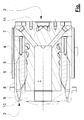
- an embodiment of the invention is shown schematically.
- the figure shows a section of an extrusion die 1 with a melt inlet 2 and a melt outlet 3.
- the melt via a Vorvermaschinelement 11, as for example from the DE 103 15 906 A1 known is brought from the cylindrical shape into a ring shape.
- the helical channel of the pre-distribution element forms with the distribution element 6 and parts of the connecting ring 4, a first melt channel 5.
- the distribution element 6 shown here as a cut block is exemplified here as a screen basket, wherein the plurality of individual holes is not shown.
- the distribution element 6 is connected by means of screws 7 fixed to the connecting ring 4.
- the connecting ring 4 is supported on other parts of the device and is therefore not displaceable.
- a defined gap 9 results between the distribution element 6 and the base part 10 of the tool.
- this gap can be changed in its width, which is made possible for example by attaching a disc between the distributor element 6 and the connecting ring 4.
- a second melt channel 8 is formed by the distribution element 6 and the connecting ring 4. This second melt channel 8 continues in the extrusion direction along the base part 10 and the connecting ring 4 and forms the melt outlet 3.
- the device proposed here is intended in particular for the processing of pipes. Basically, this system with the bypass, that is the gap between the first and second melt channel, but also for the production of other profiles or plates usable.
Landscapes
- Engineering & Computer Science (AREA)
- Mechanical Engineering (AREA)
- Manufacturing & Machinery (AREA)
- Extrusion Moulding Of Plastics Or The Like (AREA)
Claims (11)
- Dispositif pour distribuer une masse en matière plastique dans un outil d'extrusion (1), notamment un outil d'extrusion tubulaire, comprenant :un canal pour la matière en fusion (5, 8), une entrée pour la matière en fusion (2) et au moins une sortie pour la matière en fusion (3),un élément de distribution (6) étant disposé entre l'entrée pour la matière en fusion (2) et la sortie pour la matière en fusion (3) dans le canal pour la matière en fusion (5, 8) de l'outil d'extrusion, etl'élément de distribution (6) s'étendant axialement entre l'entrée pour la matière en fusion et la sortie pour la matière en fusion dans la direction d'extrusion ou d'écoulement, de telle sorte que des alésages de passage soient réalisés dans l'élément de distribution (6) perpendiculairement à la direction d'extrusion ou d'écoulement, de telle sortequ'en amont soit définie une région de l'entrée pour la matière en fusion (2) et en aval soit définie une région de la sortie pour la matière en fusion (3), etdes moyens (7) étant prévus pour la fixation de l'élément de distribution (6) sur une bague de connexion (4) de l'outil d'extrusion (1),caractérisé en ce que
l'élément de distribution (6) est connecté dans la région de l'entrée pour la matière en fusion (2) à la bague de connexion (4) de telle sorte que dans la région de la sortie pour la matière en fusion (3) dans le canal pour la matière en fusion (5, 8), un interstice défini (9) soit formé afin de former une dérivation pour contourner partiellement l'élément de distribution (6). - Dispositif selon la revendication 1, caractérisé en ce que l'élément de distribution (6) est vissé à la bague de connexion (4).
- Dispositif selon la revendication 1 ou 2, caractérisé en ce que l'élément de distribution (6) est un panier à crible, une plaque à crible ou un distributeur radial.
- Dispositif selon l'une quelconque des revendications précédentes, caractérisé en ce que l'interstice défini (9) est un interstice annulaire.
- Dispositif selon au moins l'une quelconque des revendications précédentes, caractérisé en ce qu'un premier canal pour la matière en fusion (5) est formé entre l'élément de distribution (6) et un élément de distribution préalable (11).
- Dispositif selon au moins l'une quelconque des revendications précédentes, caractérisé en ce qu'un deuxième canal pour la matière en fusion (8) est formé entre l'élément de distribution (6) et la bague de connexion (4).
- Dispositif selon la revendication 5 ou 6, caractérisé en ce que l'interstice défini (9) est une dérivation entre le premier (5) et le deuxième (8) canal pour la matière en fusion.
- Dispositif selon la revendication 7, caractérisé en ce que la largeur de l'interstice défini (9) peut être variée.
- Dispositif selon la revendication 8, caractérisé en ce que la variation de la largeur de l'interstice défini (9) peut être effectuée au moyen d'un réglage thermique, thermomécanique, électromécanique, ou mécanique.
- Procédé pour distribuer une masse en matière plastique dans un outil d'extrusion (1), notamment un outil d'extrusion tubulaire, comprenant un canal pour la matière en fusion (5, 8), une entrée pour la matière en fusion (2) et au moins une sortie pour la matière en fusion (3), et comprenant en outre :- la fourniture d'un élément de distribution (6) entre l'entrée pour la matière en fusion (2) et la sortie pour la matière en fusion (3) dans le canal pour la matière en fusion (5, 8) de l'outil d'extrusion,l'élément de distribution (6) s'étendant axialement entre l'entrée pour la matière en fusion et la sortie pour la matière en fusion dans la direction d'extrusion ou d'écoulement, de telle sorte que des alésages de passage soient prévus dans l'élément de distribution (6) perpendiculairement à la direction d'extrusion ou d'écoulement, de telle sorte qu'en amont soit définie une région de l'entrée pour la matière en fusion (2) et en aval soit définie une région de la sortie pour la matière en fusion (3),- la fourniture de moyens (7) pour la fixation de l'élément de distribution (6) sur une bague de connexion (4) de l'outil d'extrusion (1),caractérisé en ce que
l'élément de distribution (6) est connecté dans la région (du côté) de l'entrée pour la matière en fusion (2) à la bague de connexion (4) de telle sorte que dans la région de la sortie pour la matière en fusion (3) dans le canal pour la matière en fusion (5, 8), un interstice défini (9) soit formé afin de former une dérivation pour contourner partiellement l'élément de distribution (6). - Procédé selon la revendication 10, caractérisé en ce que la largeur de l'interstice défini (9) peut être variée en fonction de la surface intérieure mesurée du profilé et/ou la quantité de passage de la masse en matière plastique à travers l'interstice défini (9) peut être variée par un influence par voie thermique.
Priority Applications (1)
| Application Number | Priority Date | Filing Date | Title |
|---|---|---|---|
| PL08150120T PL1955837T3 (pl) | 2007-02-10 | 2008-01-09 | Urządzenie i sposób rozdzielania masy plastycznej tworzywa sztucznego |
Applications Claiming Priority (1)
| Application Number | Priority Date | Filing Date | Title |
|---|---|---|---|
| DE102007006610A DE102007006610B4 (de) | 2007-02-10 | 2007-02-10 | Vorrichtung und Verfahren zum Verteilen von plastischer Kunststoffmasse |
Publications (2)
| Publication Number | Publication Date |
|---|---|
| EP1955837A1 EP1955837A1 (fr) | 2008-08-13 |
| EP1955837B1 true EP1955837B1 (fr) | 2013-03-13 |
Family
ID=39430982
Family Applications (1)
| Application Number | Title | Priority Date | Filing Date |
|---|---|---|---|
| EP08150120A Active EP1955837B1 (fr) | 2007-02-10 | 2008-01-09 | Dispositif et procédé destinés à répartir une masse en matière plastique |
Country Status (5)
| Country | Link |
|---|---|
| EP (1) | EP1955837B1 (fr) |
| DE (1) | DE102007006610B4 (fr) |
| ES (1) | ES2414255T3 (fr) |
| PL (1) | PL1955837T3 (fr) |
| PT (1) | PT1955837E (fr) |
Cited By (1)
| Publication number | Priority date | Publication date | Assignee | Title |
|---|---|---|---|---|
| CN106393638A (zh) * | 2016-11-14 | 2017-02-15 | 盐城工学院 | 一种挤出机头 |
Family Cites Families (5)
| Publication number | Priority date | Publication date | Assignee | Title |
|---|---|---|---|---|
| LU34234A1 (fr) * | 1955-08-23 | 1900-01-01 | ||
| DE19846158A1 (de) * | 1998-10-07 | 2000-04-13 | Adolf Franck | Extrusionswerkzeug für die Herstellung von Hohlprofilen |
| US20020163099A1 (en) * | 2001-05-01 | 2002-11-07 | Paul Hendess | Spiral flow head assembly for polymer extrusion |
| JP2002347101A (ja) * | 2001-05-22 | 2002-12-04 | Sekisui Chem Co Ltd | シート状成形品の製造装置およびシート状成形品の製造方法 |
| DE10315906B4 (de) * | 2003-04-08 | 2006-09-28 | Battenfeld Extrusionstechnik Gmbh | Vorrichtung zum Verteilen von plastischer Kunststoffmasse |
-
2007
- 2007-02-10 DE DE102007006610A patent/DE102007006610B4/de not_active Expired - Fee Related
-
2008
- 2008-01-09 EP EP08150120A patent/EP1955837B1/fr active Active
- 2008-01-09 PL PL08150120T patent/PL1955837T3/pl unknown
- 2008-01-09 PT PT81501207T patent/PT1955837E/pt unknown
- 2008-01-09 ES ES08150120T patent/ES2414255T3/es active Active
Cited By (2)
| Publication number | Priority date | Publication date | Assignee | Title |
|---|---|---|---|---|
| CN106393638A (zh) * | 2016-11-14 | 2017-02-15 | 盐城工学院 | 一种挤出机头 |
| CN106393638B (zh) * | 2016-11-14 | 2018-08-17 | 盐城工学院 | 一种挤出机头 |
Also Published As
| Publication number | Publication date |
|---|---|
| PL1955837T3 (pl) | 2013-08-30 |
| PT1955837E (pt) | 2013-06-17 |
| DE102007006610B4 (de) | 2011-04-21 |
| DE102007006610A1 (de) | 2008-08-14 |
| ES2414255T3 (es) | 2013-07-18 |
| EP1955837A1 (fr) | 2008-08-13 |
Similar Documents
| Publication | Publication Date | Title |
|---|---|---|
| EP2212089B1 (fr) | Filière d'extrusion et procédé pour refroidir des profilés extrudés de matière plastique | |
| EP2873508B1 (fr) | Tête d'extrusion | |
| EP3589476B1 (fr) | Tête d'impression, procédé et système d'impression 3d avec débit variable | |
| EP4045274A1 (fr) | Composant pour ligne d'extrusion | |
| DE19636067A1 (de) | Filtervorrichtung zur Filtration von Kunststoffschmelze | |
| DE102009017499B4 (de) | Folienbahnformvorrichtung und Folienbahnformverfahren | |
| DE1504253C3 (de) | Längsspritzkopf mit Dorn zum Herstellen von Hohlprofilen | |
| EP1955837B1 (fr) | Dispositif et procédé destinés à répartir une masse en matière plastique | |
| DE102012025259B4 (de) | Blockträger mit integrierter Stranggießeinrichtung für thermoplastische Kunststoffe sowie Granuliervorrichtung | |
| EP3822569B1 (fr) | Echangeur de chaleur | |
| AT410195B (de) | Verfahren und einrichtung zur anpassung eines extrusionswerkzeuges an einen extruder | |
| EP2666611B1 (fr) | Procédé et dispositif destinés à tempérer une masse en matière plastique | |
| EP1466716B1 (fr) | Installation de distribution pour composition plastique plastifiée | |
| DE102010023302B4 (de) | Wendelverteiler, Blaskopf, Blasfolienanlage, Verfahren zum Herstellen einer Blasfolie | |
| EP0595198A1 (fr) | Appareil et méthode pour la fabrication de profilés allongés en matières plastiques | |
| DE1959348A1 (de) | Verfahren und Vorrichtung zum Extrudieren von thermoplastischem Kunststoff | |
| EP0593892B1 (fr) | Outil de façonnage pour extrudeuses | |
| DE4115229C2 (de) | Verfahren und Vorrichtung zur Herstellung von mehrschichtigen Schlauchfolien oder Rohren | |
| EP1916087A1 (fr) | Dispositif destiné à l'application de matière synthétique sur une pièce à usiner | |
| DE2722933A1 (de) | Mischvorrichtung | |
| EP1985433B1 (fr) | Procédé de fabrication de profilés en plastique tubulaires | |
| WO2017001310A1 (fr) | Dispositif et procédé de formation de gouttes à partir d'un produit fluide | |
| EP3287254B1 (fr) | Structure de mélangeur pour un outil pour film et outil pour film | |
| DE10307335A1 (de) | Verfahren und Vorrichtung zur Ermittlung der Masseströme | |
| DE3049522A1 (de) | Extrusionswerkzeug mit seitlichem extruderanschluss und vorkehrung zum ausgleich umlenkungsbedingter stroemungsfehler im kunststoff-massestrom |
Legal Events
| Date | Code | Title | Description |
|---|---|---|---|
| PUAI | Public reference made under article 153(3) epc to a published international application that has entered the european phase |
Free format text: ORIGINAL CODE: 0009012 |
|
| AK | Designated contracting states |
Kind code of ref document: A1 Designated state(s): AT BE BG CH CY CZ DE DK EE ES FI FR GB GR HR HU IE IS IT LI LT LU LV MC MT NL NO PL PT RO SE SI SK TR |
|
| AX | Request for extension of the european patent |
Extension state: AL BA MK RS |
|
| 17P | Request for examination filed |
Effective date: 20090213 |
|
| 17Q | First examination report despatched |
Effective date: 20090316 |
|
| AKX | Designation fees paid |
Designated state(s): AT BE BG CH CY CZ DE DK EE ES FI FR GB GR HR HU IE IS IT LI LT LU LV MC MT NL NO PL PT RO SE SI SK TR |
|
| RAP1 | Party data changed (applicant data changed or rights of an application transferred) |
Owner name: BATTENFELD-CINCINNATI GERMANY GMBH |
|
| RAP1 | Party data changed (applicant data changed or rights of an application transferred) |
Owner name: BATTENFELD-CINCINNATI GERMANY GMBH |
|
| GRAP | Despatch of communication of intention to grant a patent |
Free format text: ORIGINAL CODE: EPIDOSNIGR1 |
|
| GRAS | Grant fee paid |
Free format text: ORIGINAL CODE: EPIDOSNIGR3 |
|
| GRAA | (expected) grant |
Free format text: ORIGINAL CODE: 0009210 |
|
| AK | Designated contracting states |
Kind code of ref document: B1 Designated state(s): AT BE BG CH CY CZ DE DK EE ES FI FR GB GR HR HU IE IS IT LI LT LU LV MC MT NL NO PL PT RO SE SI SK TR |
|
| REG | Reference to a national code |
Ref country code: GB Ref legal event code: FG4D Free format text: NOT ENGLISH |
|
| REG | Reference to a national code |
Ref country code: CH Ref legal event code: EP Ref country code: AT Ref legal event code: REF Ref document number: 600513 Country of ref document: AT Kind code of ref document: T Effective date: 20130315 |
|
| REG | Reference to a national code |
Ref country code: IE Ref legal event code: FG4D Free format text: LANGUAGE OF EP DOCUMENT: GERMAN |
|
| REG | Reference to a national code |
Ref country code: DE Ref legal event code: R096 Ref document number: 502008009453 Country of ref document: DE Effective date: 20130508 |
|
| REG | Reference to a national code |
Ref country code: PT Ref legal event code: SC4A Free format text: AVAILABILITY OF NATIONAL TRANSLATION Effective date: 20130606 |
|
| REG | Reference to a national code |
Ref country code: ES Ref legal event code: FG2A Ref document number: 2414255 Country of ref document: ES Kind code of ref document: T3 Effective date: 20130718 |
|
| PG25 | Lapsed in a contracting state [announced via postgrant information from national office to epo] |
Ref country code: NO Free format text: LAPSE BECAUSE OF FAILURE TO SUBMIT A TRANSLATION OF THE DESCRIPTION OR TO PAY THE FEE WITHIN THE PRESCRIBED TIME-LIMIT Effective date: 20130613 Ref country code: SE Free format text: LAPSE BECAUSE OF FAILURE TO SUBMIT A TRANSLATION OF THE DESCRIPTION OR TO PAY THE FEE WITHIN THE PRESCRIBED TIME-LIMIT Effective date: 20130313 Ref country code: BG Free format text: LAPSE BECAUSE OF FAILURE TO SUBMIT A TRANSLATION OF THE DESCRIPTION OR TO PAY THE FEE WITHIN THE PRESCRIBED TIME-LIMIT Effective date: 20130613 Ref country code: LT Free format text: LAPSE BECAUSE OF FAILURE TO SUBMIT A TRANSLATION OF THE DESCRIPTION OR TO PAY THE FEE WITHIN THE PRESCRIBED TIME-LIMIT Effective date: 20130313 |
|
| REG | Reference to a national code |
Ref country code: NL Ref legal event code: T3 |
|
| REG | Reference to a national code |
Ref country code: LT Ref legal event code: MG4D |
|
| PG25 | Lapsed in a contracting state [announced via postgrant information from national office to epo] |
Ref country code: SI Free format text: LAPSE BECAUSE OF FAILURE TO SUBMIT A TRANSLATION OF THE DESCRIPTION OR TO PAY THE FEE WITHIN THE PRESCRIBED TIME-LIMIT Effective date: 20130313 Ref country code: GR Free format text: LAPSE BECAUSE OF FAILURE TO SUBMIT A TRANSLATION OF THE DESCRIPTION OR TO PAY THE FEE WITHIN THE PRESCRIBED TIME-LIMIT Effective date: 20130614 Ref country code: FI Free format text: LAPSE BECAUSE OF FAILURE TO SUBMIT A TRANSLATION OF THE DESCRIPTION OR TO PAY THE FEE WITHIN THE PRESCRIBED TIME-LIMIT Effective date: 20130313 Ref country code: LV Free format text: LAPSE BECAUSE OF FAILURE TO SUBMIT A TRANSLATION OF THE DESCRIPTION OR TO PAY THE FEE WITHIN THE PRESCRIBED TIME-LIMIT Effective date: 20130313 |
|
| REG | Reference to a national code |
Ref country code: PL Ref legal event code: T3 |
|
| PG25 | Lapsed in a contracting state [announced via postgrant information from national office to epo] |
Ref country code: HR Free format text: LAPSE BECAUSE OF FAILURE TO SUBMIT A TRANSLATION OF THE DESCRIPTION OR TO PAY THE FEE WITHIN THE PRESCRIBED TIME-LIMIT Effective date: 20130313 |
|
| PG25 | Lapsed in a contracting state [announced via postgrant information from national office to epo] |
Ref country code: SK Free format text: LAPSE BECAUSE OF FAILURE TO SUBMIT A TRANSLATION OF THE DESCRIPTION OR TO PAY THE FEE WITHIN THE PRESCRIBED TIME-LIMIT Effective date: 20130313 Ref country code: EE Free format text: LAPSE BECAUSE OF FAILURE TO SUBMIT A TRANSLATION OF THE DESCRIPTION OR TO PAY THE FEE WITHIN THE PRESCRIBED TIME-LIMIT Effective date: 20130313 Ref country code: RO Free format text: LAPSE BECAUSE OF FAILURE TO SUBMIT A TRANSLATION OF THE DESCRIPTION OR TO PAY THE FEE WITHIN THE PRESCRIBED TIME-LIMIT Effective date: 20130313 Ref country code: IS Free format text: LAPSE BECAUSE OF FAILURE TO SUBMIT A TRANSLATION OF THE DESCRIPTION OR TO PAY THE FEE WITHIN THE PRESCRIBED TIME-LIMIT Effective date: 20130713 Ref country code: CZ Free format text: LAPSE BECAUSE OF FAILURE TO SUBMIT A TRANSLATION OF THE DESCRIPTION OR TO PAY THE FEE WITHIN THE PRESCRIBED TIME-LIMIT Effective date: 20130313 |
|
| PG25 | Lapsed in a contracting state [announced via postgrant information from national office to epo] |
Ref country code: CY Free format text: LAPSE BECAUSE OF FAILURE TO SUBMIT A TRANSLATION OF THE DESCRIPTION OR TO PAY THE FEE WITHIN THE PRESCRIBED TIME-LIMIT Effective date: 20130313 |
|
| PLBE | No opposition filed within time limit |
Free format text: ORIGINAL CODE: 0009261 |
|
| STAA | Information on the status of an ep patent application or granted ep patent |
Free format text: STATUS: NO OPPOSITION FILED WITHIN TIME LIMIT |
|
| PG25 | Lapsed in a contracting state [announced via postgrant information from national office to epo] |
Ref country code: DK Free format text: LAPSE BECAUSE OF FAILURE TO SUBMIT A TRANSLATION OF THE DESCRIPTION OR TO PAY THE FEE WITHIN THE PRESCRIBED TIME-LIMIT Effective date: 20130313 |
|
| 26N | No opposition filed |
Effective date: 20131216 |
|
| REG | Reference to a national code |
Ref country code: DE Ref legal event code: R097 Ref document number: 502008009453 Country of ref document: DE Effective date: 20131216 |
|
| BERE | Be: lapsed |
Owner name: BATTENFELD-CINCINNATI GERMANY G.M.B.H. Effective date: 20140131 |
|
| PG25 | Lapsed in a contracting state [announced via postgrant information from national office to epo] |
Ref country code: LU Free format text: LAPSE BECAUSE OF FAILURE TO SUBMIT A TRANSLATION OF THE DESCRIPTION OR TO PAY THE FEE WITHIN THE PRESCRIBED TIME-LIMIT Effective date: 20140109 Ref country code: MC Free format text: LAPSE BECAUSE OF FAILURE TO SUBMIT A TRANSLATION OF THE DESCRIPTION OR TO PAY THE FEE WITHIN THE PRESCRIBED TIME-LIMIT Effective date: 20130313 |
|
| REG | Reference to a national code |
Ref country code: CH Ref legal event code: PL |
|
| PG25 | Lapsed in a contracting state [announced via postgrant information from national office to epo] |
Ref country code: LI Free format text: LAPSE BECAUSE OF NON-PAYMENT OF DUE FEES Effective date: 20140131 Ref country code: CH Free format text: LAPSE BECAUSE OF NON-PAYMENT OF DUE FEES Effective date: 20140131 |
|
| REG | Reference to a national code |
Ref country code: IE Ref legal event code: MM4A |
|
| PG25 | Lapsed in a contracting state [announced via postgrant information from national office to epo] |
Ref country code: BE Free format text: LAPSE BECAUSE OF NON-PAYMENT OF DUE FEES Effective date: 20140131 Ref country code: IE Free format text: LAPSE BECAUSE OF NON-PAYMENT OF DUE FEES Effective date: 20140109 |
|
| REG | Reference to a national code |
Ref country code: FR Ref legal event code: PLFP Year of fee payment: 9 |
|
| PG25 | Lapsed in a contracting state [announced via postgrant information from national office to epo] |
Ref country code: MT Free format text: LAPSE BECAUSE OF FAILURE TO SUBMIT A TRANSLATION OF THE DESCRIPTION OR TO PAY THE FEE WITHIN THE PRESCRIBED TIME-LIMIT Effective date: 20130313 |
|
| PG25 | Lapsed in a contracting state [announced via postgrant information from national office to epo] |
Ref country code: HU Free format text: LAPSE BECAUSE OF FAILURE TO SUBMIT A TRANSLATION OF THE DESCRIPTION OR TO PAY THE FEE WITHIN THE PRESCRIBED TIME-LIMIT; INVALID AB INITIO Effective date: 20080109 |
|
| REG | Reference to a national code |
Ref country code: FR Ref legal event code: PLFP Year of fee payment: 10 |
|
| REG | Reference to a national code |
Ref country code: FR Ref legal event code: PLFP Year of fee payment: 11 |
|
| REG | Reference to a national code |
Ref country code: DE Ref legal event code: R079 Ref document number: 502008009453 Country of ref document: DE Free format text: PREVIOUS MAIN CLASS: B29C0047200000 Ipc: B29C0048320000 |
|
| P01 | Opt-out of the competence of the unified patent court (upc) registered |
Effective date: 20230527 |
|
| PGFP | Annual fee paid to national office [announced via postgrant information from national office to epo] |
Ref country code: NL Payment date: 20260121 Year of fee payment: 19 |
|
| PGFP | Annual fee paid to national office [announced via postgrant information from national office to epo] |
Ref country code: GB Payment date: 20260122 Year of fee payment: 19 |
|
| PGFP | Annual fee paid to national office [announced via postgrant information from national office to epo] |
Ref country code: ES Payment date: 20260217 Year of fee payment: 19 |
|
| PGFP | Annual fee paid to national office [announced via postgrant information from national office to epo] |
Ref country code: DE Payment date: 20260131 Year of fee payment: 19 |
|
| PGFP | Annual fee paid to national office [announced via postgrant information from national office to epo] |
Ref country code: AT Payment date: 20260119 Year of fee payment: 19 |
|
| PGFP | Annual fee paid to national office [announced via postgrant information from national office to epo] |
Ref country code: IT Payment date: 20260130 Year of fee payment: 19 |
|
| PGFP | Annual fee paid to national office [announced via postgrant information from national office to epo] |
Ref country code: FR Payment date: 20260127 Year of fee payment: 19 |
|
| PGFP | Annual fee paid to national office [announced via postgrant information from national office to epo] |
Ref country code: TR Payment date: 20260108 Year of fee payment: 19 |
|
| PGFP | Annual fee paid to national office [announced via postgrant information from national office to epo] |
Ref country code: PT Payment date: 20260108 Year of fee payment: 19 |
|
| PGFP | Annual fee paid to national office [announced via postgrant information from national office to epo] |
Ref country code: PL Payment date: 20260102 Year of fee payment: 19 |