EP1955838A2 - Vorrichtung zur Unterstützung von Kunststoffprofilen - Google Patents
Vorrichtung zur Unterstützung von Kunststoffprofilen Download PDFInfo
- Publication number
- EP1955838A2 EP1955838A2 EP08002488A EP08002488A EP1955838A2 EP 1955838 A2 EP1955838 A2 EP 1955838A2 EP 08002488 A EP08002488 A EP 08002488A EP 08002488 A EP08002488 A EP 08002488A EP 1955838 A2 EP1955838 A2 EP 1955838A2
- Authority
- EP
- European Patent Office
- Prior art keywords
- base frame
- link chain
- plastic profile
- wedge surface
- support
- Prior art date
- Legal status (The legal status is an assumption and is not a legal conclusion. Google has not performed a legal analysis and makes no representation as to the accuracy of the status listed.)
- Withdrawn
Links
- 229920003023 plastic Polymers 0.000 title claims abstract 13
- 239000004033 plastic Substances 0.000 title claims abstract 13
- 238000006073 displacement reaction Methods 0.000 claims abstract 2
- 238000001125 extrusion Methods 0.000 claims abstract 2
- 229920003020 cross-linked polyethylene Polymers 0.000 claims 1
- 239000004703 cross-linked polyethylene Substances 0.000 claims 1
- 230000003068 static effect Effects 0.000 claims 1
Images

Classifications
-
- B—PERFORMING OPERATIONS; TRANSPORTING
- B29—WORKING OF PLASTICS; WORKING OF SUBSTANCES IN A PLASTIC STATE IN GENERAL
- B29C—SHAPING OR JOINING OF PLASTICS; SHAPING OF MATERIAL IN A PLASTIC STATE, NOT OTHERWISE PROVIDED FOR; AFTER-TREATMENT OF THE SHAPED PRODUCTS, e.g. REPAIRING
- B29C48/00—Extrusion moulding, i.e. expressing the moulding material through a die or nozzle which imparts the desired form; Apparatus therefor
- B29C48/25—Component parts, details or accessories; Auxiliary operations
- B29C48/88—Thermal treatment of the stream of extruded material, e.g. cooling
- B29C48/90—Thermal treatment of the stream of extruded material, e.g. cooling with calibration or sizing, i.e. combined with fixing or setting of the final dimensions of the extruded article
- B29C48/907—Thermal treatment of the stream of extruded material, e.g. cooling with calibration or sizing, i.e. combined with fixing or setting of the final dimensions of the extruded article using adjustable calibrators, e.g. the dimensions of the calibrator being changeable
-
- B—PERFORMING OPERATIONS; TRANSPORTING
- B29—WORKING OF PLASTICS; WORKING OF SUBSTANCES IN A PLASTIC STATE IN GENERAL
- B29C—SHAPING OR JOINING OF PLASTICS; SHAPING OF MATERIAL IN A PLASTIC STATE, NOT OTHERWISE PROVIDED FOR; AFTER-TREATMENT OF THE SHAPED PRODUCTS, e.g. REPAIRING
- B29C48/00—Extrusion moulding, i.e. expressing the moulding material through a die or nozzle which imparts the desired form; Apparatus therefor
- B29C48/03—Extrusion moulding, i.e. expressing the moulding material through a die or nozzle which imparts the desired form; Apparatus therefor characterised by the shape of the extruded material at extrusion
- B29C48/09—Articles with cross-sections having partially or fully enclosed cavities, e.g. pipes or channels
-
- B—PERFORMING OPERATIONS; TRANSPORTING
- B29—WORKING OF PLASTICS; WORKING OF SUBSTANCES IN A PLASTIC STATE IN GENERAL
- B29C—SHAPING OR JOINING OF PLASTICS; SHAPING OF MATERIAL IN A PLASTIC STATE, NOT OTHERWISE PROVIDED FOR; AFTER-TREATMENT OF THE SHAPED PRODUCTS, e.g. REPAIRING
- B29C48/00—Extrusion moulding, i.e. expressing the moulding material through a die or nozzle which imparts the desired form; Apparatus therefor
- B29C48/25—Component parts, details or accessories; Auxiliary operations
- B29C48/355—Conveyors for extruded articles
-
- B—PERFORMING OPERATIONS; TRANSPORTING
- B29—WORKING OF PLASTICS; WORKING OF SUBSTANCES IN A PLASTIC STATE IN GENERAL
- B29C—SHAPING OR JOINING OF PLASTICS; SHAPING OF MATERIAL IN A PLASTIC STATE, NOT OTHERWISE PROVIDED FOR; AFTER-TREATMENT OF THE SHAPED PRODUCTS, e.g. REPAIRING
- B29C48/00—Extrusion moulding, i.e. expressing the moulding material through a die or nozzle which imparts the desired form; Apparatus therefor
- B29C48/25—Component parts, details or accessories; Auxiliary operations
- B29C48/88—Thermal treatment of the stream of extruded material, e.g. cooling
- B29C48/90—Thermal treatment of the stream of extruded material, e.g. cooling with calibration or sizing, i.e. combined with fixing or setting of the final dimensions of the extruded article
- B29C48/901—Thermal treatment of the stream of extruded material, e.g. cooling with calibration or sizing, i.e. combined with fixing or setting of the final dimensions of the extruded article of hollow bodies
- B29C48/903—Thermal treatment of the stream of extruded material, e.g. cooling with calibration or sizing, i.e. combined with fixing or setting of the final dimensions of the extruded article of hollow bodies externally
-
- B—PERFORMING OPERATIONS; TRANSPORTING
- B29—WORKING OF PLASTICS; WORKING OF SUBSTANCES IN A PLASTIC STATE IN GENERAL
- B29C—SHAPING OR JOINING OF PLASTICS; SHAPING OF MATERIAL IN A PLASTIC STATE, NOT OTHERWISE PROVIDED FOR; AFTER-TREATMENT OF THE SHAPED PRODUCTS, e.g. REPAIRING
- B29C48/00—Extrusion moulding, i.e. expressing the moulding material through a die or nozzle which imparts the desired form; Apparatus therefor
- B29C48/25—Component parts, details or accessories; Auxiliary operations
- B29C48/88—Thermal treatment of the stream of extruded material, e.g. cooling
- B29C48/90—Thermal treatment of the stream of extruded material, e.g. cooling with calibration or sizing, i.e. combined with fixing or setting of the final dimensions of the extruded article
- B29C48/905—Thermal treatment of the stream of extruded material, e.g. cooling with calibration or sizing, i.e. combined with fixing or setting of the final dimensions of the extruded article using wet calibration, i.e. in a quenching tank
-
- B—PERFORMING OPERATIONS; TRANSPORTING
- B29—WORKING OF PLASTICS; WORKING OF SUBSTANCES IN A PLASTIC STATE IN GENERAL
- B29C—SHAPING OR JOINING OF PLASTICS; SHAPING OF MATERIAL IN A PLASTIC STATE, NOT OTHERWISE PROVIDED FOR; AFTER-TREATMENT OF THE SHAPED PRODUCTS, e.g. REPAIRING
- B29C48/00—Extrusion moulding, i.e. expressing the moulding material through a die or nozzle which imparts the desired form; Apparatus therefor
- B29C48/25—Component parts, details or accessories; Auxiliary operations
- B29C48/92—Measuring, controlling or regulating
-
- B—PERFORMING OPERATIONS; TRANSPORTING
- B29—WORKING OF PLASTICS; WORKING OF SUBSTANCES IN A PLASTIC STATE IN GENERAL
- B29C—SHAPING OR JOINING OF PLASTICS; SHAPING OF MATERIAL IN A PLASTIC STATE, NOT OTHERWISE PROVIDED FOR; AFTER-TREATMENT OF THE SHAPED PRODUCTS, e.g. REPAIRING
- B29C2948/00—Indexing scheme relating to extrusion moulding
- B29C2948/92—Measuring, controlling or regulating
- B29C2948/92009—Measured parameter
- B29C2948/92114—Dimensions
- B29C2948/92123—Diameter or circumference
-
- B—PERFORMING OPERATIONS; TRANSPORTING
- B29—WORKING OF PLASTICS; WORKING OF SUBSTANCES IN A PLASTIC STATE IN GENERAL
- B29C—SHAPING OR JOINING OF PLASTICS; SHAPING OF MATERIAL IN A PLASTIC STATE, NOT OTHERWISE PROVIDED FOR; AFTER-TREATMENT OF THE SHAPED PRODUCTS, e.g. REPAIRING
- B29C2948/00—Indexing scheme relating to extrusion moulding
- B29C2948/92—Measuring, controlling or regulating
- B29C2948/92504—Controlled parameter
- B29C2948/92609—Dimensions
- B29C2948/92619—Diameter or circumference
-
- B—PERFORMING OPERATIONS; TRANSPORTING
- B29—WORKING OF PLASTICS; WORKING OF SUBSTANCES IN A PLASTIC STATE IN GENERAL
- B29C—SHAPING OR JOINING OF PLASTICS; SHAPING OF MATERIAL IN A PLASTIC STATE, NOT OTHERWISE PROVIDED FOR; AFTER-TREATMENT OF THE SHAPED PRODUCTS, e.g. REPAIRING
- B29C48/00—Extrusion moulding, i.e. expressing the moulding material through a die or nozzle which imparts the desired form; Apparatus therefor
- B29C48/25—Component parts, details or accessories; Auxiliary operations
- B29C48/88—Thermal treatment of the stream of extruded material, e.g. cooling
- B29C48/885—External treatment, e.g. by using air rings for cooling tubular films
-
- B—PERFORMING OPERATIONS; TRANSPORTING
- B29—WORKING OF PLASTICS; WORKING OF SUBSTANCES IN A PLASTIC STATE IN GENERAL
- B29C—SHAPING OR JOINING OF PLASTICS; SHAPING OF MATERIAL IN A PLASTIC STATE, NOT OTHERWISE PROVIDED FOR; AFTER-TREATMENT OF THE SHAPED PRODUCTS, e.g. REPAIRING
- B29C48/00—Extrusion moulding, i.e. expressing the moulding material through a die or nozzle which imparts the desired form; Apparatus therefor
- B29C48/25—Component parts, details or accessories; Auxiliary operations
- B29C48/88—Thermal treatment of the stream of extruded material, e.g. cooling
- B29C48/90—Thermal treatment of the stream of extruded material, e.g. cooling with calibration or sizing, i.e. combined with fixing or setting of the final dimensions of the extruded article
- B29C48/908—Thermal treatment of the stream of extruded material, e.g. cooling with calibration or sizing, i.e. combined with fixing or setting of the final dimensions of the extruded article characterised by calibrator surface, e.g. structure or holes for lubrication, cooling or venting
-
- B—PERFORMING OPERATIONS; TRANSPORTING
- B29—WORKING OF PLASTICS; WORKING OF SUBSTANCES IN A PLASTIC STATE IN GENERAL
- B29C—SHAPING OR JOINING OF PLASTICS; SHAPING OF MATERIAL IN A PLASTIC STATE, NOT OTHERWISE PROVIDED FOR; AFTER-TREATMENT OF THE SHAPED PRODUCTS, e.g. REPAIRING
- B29C48/00—Extrusion moulding, i.e. expressing the moulding material through a die or nozzle which imparts the desired form; Apparatus therefor
- B29C48/25—Component parts, details or accessories; Auxiliary operations
- B29C48/88—Thermal treatment of the stream of extruded material, e.g. cooling
- B29C48/911—Cooling
- B29C48/9115—Cooling of hollow articles
- B29C48/912—Cooling of hollow articles of tubular films
-
- B—PERFORMING OPERATIONS; TRANSPORTING
- B29—WORKING OF PLASTICS; WORKING OF SUBSTANCES IN A PLASTIC STATE IN GENERAL
- B29C—SHAPING OR JOINING OF PLASTICS; SHAPING OF MATERIAL IN A PLASTIC STATE, NOT OTHERWISE PROVIDED FOR; AFTER-TREATMENT OF THE SHAPED PRODUCTS, e.g. REPAIRING
- B29C48/00—Extrusion moulding, i.e. expressing the moulding material through a die or nozzle which imparts the desired form; Apparatus therefor
- B29C48/25—Component parts, details or accessories; Auxiliary operations
- B29C48/88—Thermal treatment of the stream of extruded material, e.g. cooling
- B29C48/919—Thermal treatment of the stream of extruded material, e.g. cooling using a bath, e.g. extruding into an open bath to coagulate or cool the material
Definitions
- the present invention relates to a device for supporting plastic profiles, in particular pipes according to the preamble of claim 1.
- Such a device for supporting plastic profiles is from the DE 10 2004 059 515 B3 known.
- This device consists of a cylinder section with a matched to the cross section of a plastic profile recording for line-shaped Supplementum charged the profile circumference.
- This receptacle is designed as a groove extending in the circumferential direction of the cylinder section, the width of which widens conically from one end to the other end of the cylinder section in adaptation to different profile sizes of the plastic profile.
- the cylinder section is rotatably mounted about a pivot axis arranged transversely to the channel in order to be able to adjust the device to the respective profile size produced.
- This known from the prior art device allows a simple, continuous adaptation to the driven in an extrusion line profile dimensions with continuous Operaum charged the profile circumference. Furthermore, it is suitable as a equipment for a dimensional change during production.
- Object of the present invention is to provide a further generic support device available. This object is achieved with a support device having the features of claim 1.
- the support contour formed as a link chain adapts easily to the contour of the plastic profile, so that this by the adjoining support surface the links of the link chain is reliably supported.
- a continuous adaptation to different profile sizes of the plastic profile is achieved in a simple manner by sliding the wedge surfaces opposing wedge surfaces on counter-wedge surfaces of a base frame, whereby the link chain radially displaced.
- a second base frame with a counter-wedge surface is arranged parallel to the first base frame, which adjoins with the same slope seamless or with only a small gap to the counter-wedge surface of the first base frame.
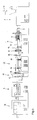
- extrusion line comprises an extruder unit 1 with a hopper 2, an extruder screw not shown in the drawing and a tube head 3.
- a thermoplastic resin 4 in granular or powder form of the extruder unit 1 supplied.
- the granules or powder is heated, kneaded and plasticized.
- the plastic 4 is conveyed as a moldable material through the extruder screw in the tube head 3 and pressed there through an annular outlet gap.
- the hot, still deformable tube 5 is pulled by means of a arranged at the end of the extrusion line caterpillar take 6 by a calibration and cooling unit 7, which has a vacuum tank 8 with a calibration arranged at its inlet 9.
- the calibration sleeve 9 is continuously adjustable in diameter, so that the extruded, still malleable tube 5 can be fixed to the desired diameter.
- the tube 5 After leaving the calibration and cooling unit 7, the tube 5 enters a cooling section 10 in which it is cooled to room temperature. Between the cooling section 10 and the caterpillar take-off 6, an ultrasonic scanner 11 is arranged, in which the diameter and the wall thickness of the extruded tube 5 are detected.
- the caterpillar take-off 6 is followed by a cutting saw 12, in which the tube 5 is cut to length.
- the cooling section 10 and the ultrasonic scanner 11 seals 13 are provided which surround the continuous tube 5 sealingly.
- a pipe support 14 are provided in the cooling section 10 and in the calibration and cooling unit 7, the structure and operation of which below with reference to Fig. 2 to 14 which show two different embodiments will be explained in more detail.
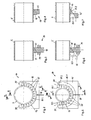
- the in the Fig. 2 to 8 shown pipe support 14 according to a first embodiment of the invention comprises a base frame 15 and a Link chain 16 on.
- the latter consists, as the name implies, of individual interconnected links 17, their structure best Fig. 8 which shows a single member 17.
- This member 17 has a rectangular support surface 17.1, which rests in operation on the circumference of the extruded plastic tube 5.
- the support surface 17.1 opposite is a wedge surface 17.2, which increases relative to the support surface 17.1 and has the shape of an isosceles trapezium.
- the two end faces 17.3 and 17.4 also have the shape of an isosceles trapezium, while the two side surfaces 17.5 have the shape of a non-isosceles trapezium.
- the wedge surface 17.2 of the links 17 rest on a counter wedge surface 15.1 of the base frame 15, which has the same pitch as the wedge surfaces 17.5 of the links 17.
- the counter-wedge surface 15.1 is also circular in cross-section in adaptation to the circular cross-section of the extruded tube 5, the smallest diameter of the counter-wedge surface 15.1 being slightly larger than the largest diameter of the extruded tube 5 to be supported.
- the members 17 are made of plastic with good sliding properties, eg. B. highly cross-linked polyethylene, and are connected to each other on the longitudinal sides of their support surfaces 17.1 articulated via film hinges not shown in the drawing. It is also possible to articulate the individual members 17 via piano straps.
- the base frame 15 is axially, ie, displaceable in the tube longitudinal direction, while the link chain 16 is axially fixed relative to the plastic tube 5 and the base frame 15.
- This location stability is achieved in that the lowermost member 17 of the link chain 16 is extended downwardly by a sword 18, which passes through a slot provided in the base frame 15, wherein this slot has such an axial extent that the stationary sword 18 does not hinder the required axial displacement of the base frame 15. At the same time this slot allows an upward and downward movement of the sword 18.
- the lower end of the sword 18 is guided in a stationary bearing 19, which also allows an upward and downward movement of the sword 18 and thus of the associated member 17.
- member 17 and sword 18 are made in one piece. But it is also possible a two-piece design.
- the Fig. 2 to 4 show the pipe support 14 in supporting the largest possible diameter of the plastic pipe 5.
- the links 17 of the link chain 16 are lowered accordingly deep on the counter-wedge surface 15.1 of the base frame 15, as shown in 3 and 4 evident.
- Optimal for effective support of the tube 5 is a 180 ° circumference of the tube circumference through the link chain 16.
- the smaller diameter for supporting support no longer required end members 17 of the link chain 16 are therefore tilted from the periphery of the plastic tube 5 to the outside, as in Fig. 5 shown.
- This tilting is done by a corresponding, deviating from the circular cross-section bend 20 of the counter-wedge surface 15.1 at the free ends of the base frame 15.
- the tilted from the periphery of the plastic tube 5 members 17 are held by a guide, not shown in the drawing in this dumped shape, so that they can not tilt back to the pipe circumference.
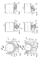
- a second base frame 21 is provided in a further embodiment of the present invention, which has a counter-wedge surface 21.1, which has the same pitch as the counter-wedge surface 15.1 of the first base frame 15.
- the second base frame 21 is divided in half, with its two halves 20.2 radially on the plastic tube 5 are deliverable, which in the FIGS. 9 and 12 is symbolically represented by arrows 22. As long as no smaller pipe diameters than those in the Fig. 5 to 7 or 12 to 14, must be supported, the second base frame 21 remains in a rest position, which in the Fig. 9 to 11 is shown. It is in Fig. 9 the position of this rest position of the second base frame 21 and its two halves 22.2 shown by dashed lines. In this rest position, the second base frame 21 does not hinder the free passage of plastic pipes 5 of larger diameter through the first base frame 15.
- the second base frame 21 is moved from its rest position to a working position in the Fig. 12 to 14 is shown.
- This working position is achieved by radial infeed (arrows 22) of the two halves 21.2 of the second base frame 21 on the plastic tube 5.
- the radial feed is completed when the counter-wedge surface 21.1 continues the counter-wedge surface 15.1 of the first base frame 15 seamlessly or only with a small gap.
- This job is best done in accordance with the presentation Fig. 14 out. From this representation it can be seen that now the members 17 of the link chain 16 can be driven on the counter-wedge surface 21.1 by axial adjustment of the base frame 15 and 21 further upwards, whereby the support even smaller pipe diameter is possible.
- the link chain 16 is held axially fixed by a connected to the bottom member 17 sword 18 and a corresponding bearing 19 relative to the plastic tube 5 and relative to the first and second base frame 15 and 21 respectively.
Landscapes
- Engineering & Computer Science (AREA)
- Mechanical Engineering (AREA)
- Physics & Mathematics (AREA)
- Thermal Sciences (AREA)
- Extrusion Moulding Of Plastics Or The Like (AREA)
Abstract
Description
- Die vorliegende Erfindung betrifft eine Vorrichtung zur Unterstützung von Kunststoffprofilen, insbesondere von Rohren gemäß dem Oberbegriff des Anspruchs 1.
- Eine derartige Vorrichtung zur Unterstützung von Kunststoffprofilen ist aus der
DE 10 2004 059 515 B3 bekannt. Diese Vorrichtung besteht aus einem Zylinderabschnitt mit einer an den Querschnitt eines Kunststoffprofils angepassten Aufnahme zur linienförmigen Teilumfassung des Profilumfangs. Diese Aufnahme ist als eine in Umfangsrichtung des Zylinderabschnitts verlaufende Rinne ausgebildet, deren Breite sich von einem Ende zum anderen Ende des Zylinderabschnitts in Anpassung an verschiedene Profilgrößen des Kunststoffprofils konisch vergrößert. Der Zylinderabschnitt ist um eine quer zu der Rinne angeordnete Schwenkachse drehbar gelagert, um die Vorrichtung auf die jeweils produzierte Profilgröße einstellen zu können. Diese aus dem Stand der Technik bekannte Vorrichtung ermöglicht eine einfache, stufenlose Anpassung an die in einer Extrusionslinie gefahrenen Profildimensionen bei kontinuierlicher Teilumfassung des Profilumfangs. Des weiteren ist sie als Ausrüstung für einen Dimensionswechsel bei laufender Produktion geeignet. - Aufgabe der vorliegenden Erfindung ist es, eine weitere gattungsgemäße Stützvorrichtung zur Verfügung zu stellen. Diese Aufgabe wird erfindungsgemäß mit einer Stützvorrichtung gelöst, die die Merkmale des Anspruchs 1 aufweist.
- Die als Gliederkette ausgebildete Stützkontur passt sich leicht an die Kontur des Kunststoffprofils an, so dass dieses durch die anliegende Stützfläche der Glieder der Gliederkette zuverlässig abgestützt ist. Dabei wird eine stufenlose Anpassung an verschiedene Profilgrößen des Kunststoffprofils auf einfache Weise dadurch erreicht, dass den Stützflächen der Glieder gegenüberliegende Keilflächen auf Gegenkeilflächen eines Grundrahmens gleiten, wodurch sich die Gliederkette radial verlagert.
- In vorteilhafter Ausgestaltung der Erfindung ist parallel zum ersten Grundrahmen ein zweiter Grundrahmen mit einer Gegenkeilfläche angeordnet, die sich mit gleicher Steigung nahtlos oder mit nur geringer Lücke an die Gegenkeilfläche des ersten Grundrahmens anschließt. Durch diese zweistufige Ausführung der Vorrichtung wird der Bereich der abstützbaren Profilgrößen erweitert.
- Andere vorteilhafte Ausgestaltungen der Erfindung ergeben sich aus den übrigen Unteransprüchen.
- Die Erfindung wird nachstehend anhand von Ausführungsbeispielen näher erläutert. In der dazugehörigen Zeichnung zeigt in schematischer Weise:
- Fig. 1
- eine Seitenansicht einer Rohrextrusionslinie,
- Fig. 2
- eine Vorderansicht einer erfindungsgemäßen Vorrichtung mit Gliederkette und einem ersten Grundrahmen in Anpassung an einen großen Rohrdurchmesser,
- Fig. 3
- einen Schnitt A-A gemäß
Fig. 2 , - Fig. 4
- einen Schnitt B-B gemäß
Fig. 2 , - Fig. 5
- eine Darstellung gemäß
Fig. 2 mit an einem kleinen Rohrdurchmesser angepasster Vorrichtung, - Fig. 6
- einen Schnitt C-C gemäß
Fig. 5 , - Fig. 7
- einen Schnitt D-D gemäß
Fig. 5 , - Fig. 8
- einen perspektivischen Blick auf einen hälftig abgeschnittenen Grundrahmen mit einem symbolisch dargestellten, aufliegenden Glied der Gliederkette,
- Fig. 9
- eine Vorderansicht einer erfindungsgemäßen Vorrichtung in einer zweiten Ausführungsform mit einem ersten und zweiten Grundrahmen und einer Gliederkette in Anpassung an einen großen Rohrdurchmesser,
- Fig. 10
- einen Schnitt E-E gemäß
Fig. 9 , - Fig. 11
- einen Schnitt F-F gemäß
Fig. 9 , - Fig. 12
- eine Darstellung gemäß
Fig. 9 in Anpassung an einen kleinen Rohrdurchmesser, - Fig. 13
- einen Schnitt G-G gemäß
Fig. 12 , und - Fig. 14
- einen Schnitt H-H gemäß
Fig. 12 . - Die in
Fig. 1 dargestellte Extrusionslinie umfasst eine Extrudereinheit 1 mit einem Aufgabetrichter 2, eine aus der Zeichnung nicht ersichtlichen Extruderschnecke und einen Rohrkopf 3. Über den Aufgabetrichter 2 wird ein thermoplastischer Kunststoff 4 in Granulat- oder Pulverform der Extrudereinheit 1 zugeführt. In dieser wird das Granulat bzw. Pulver erwärmt, geknetet und plastifiziert. Anschließend wird der Kunststoff 4 als formbare Masse durch die Extruderschnecke in den Rohrkopf 3 gefördert und dort durch einen ringförmigen Austrittsspalt gedrückt. - Nach dem Austritt aus dem Rohrkopf 3 wird das heiße, noch verformbare Rohr 5 mittels eines am Ende der Extrusionslinie angeordneten Raupenabzugs 6 durch eine Kalibrier- und Kühleinheit 7 gezogen, die einen Vakuumtank 8 mit einer an dessem Eingang angeordneten Kalibrierhülse 9 aufweist. Die Kalibrierhülse 9 ist stufenlos im Durchmesser einstellbar, so dass das extrudierte, noch formbare Rohr 5 auf den gewünschten Durchmesser fixiert werden kann. Nach dem Verlassen der Kalibrier- und Kühleinheit 7 tritt das Rohr 5 in eine Kühlstrecke 10 ein, in der es auf Raumtemperatur abgekühlt wird. Zwischen der Kühlstrecke 10 und dem Raupenabzug 6 ist ein Ultraschallscanner 11 angeordnet, in dem der Durchmesser und die Wanddicke des extrudierten Rohres 5 erfasst werden. Dem Raupenabzug 6 schließt sich eine Trennsäge 12 an, in der das Rohr 5 abgelängt wird. Zur Aufrechterhaltung eines Unterdrucks in der Kalibrier- und Kühleinheit 7, der Kühlstrecke 10 und dem Ultraschallscanner 11 sind Dichtungen 13 vorgesehen, die das durchlaufende Rohr 5 abdichtend umschließen.
- Da das extrudierte Rohr 5 erst nach Verlassen der Kühlstrecke 10 ausgehärtet, d.h. formstabil ist, muss es zuvor abgestützt werden, um ein Durchhängen und damit Deformieren zu vermeiden. Dazu sind in der Kühlstrecke 10 zwei und in der Kalibrier- und Kühleinheit 7 eine Rohrunterstützung 14 vorgesehen, deren Aufbau und Wirkungsweise nachstehend anhand der
Fig. 2 bis 14 , die zwei verschiedene Ausführungsformen zeigen, näher erläutert wird. - Die in den
Fig. 2 bis 8 gezeigte Rohrunterstützung 14 gemäß einer ersten Ausführungsform der Erfindung weist einen Grundrahmen 15 und eine Gliederkette 16 auf. Letztere besteht, wie der Name schon sagt, aus einzelnen miteinander verbundenen Gliedern 17, deren Aufbau am besten ausFig. 8 hervorgeht, die ein einzelnes Glied 17 zeigt. Dieses Glied 17 besitzt eine rechteckige Stützfläche 17.1, die im Betrieb am Umfang des extrudierten Kunststoffrohres 5 anliegt. Der Stützfläche 17.1 gegenüber liegt eine Keilfläche 17.2, die gegenüber der Stützfläche 17.1 ansteigt und die Form eines gleichschenkligen Trapezes hat. Die beiden Stirnflächen 17.3 und 17.4 besitzen ebenfalls die Form eines gleichschenkligen Trapezes, während die beiden Seitenflächen 17.5 die Form eines ungleichschenkligen Trapezes aufweisen. - Die Keilfläche 17.2 der Glieder 17 liegen auf einer Gegenkeilfläche 15.1 des Grundrahmens 15 auf, die die gleiche Steigung wie die Keilflächen 17.5 der Glieder 17 aufweist. Die Gegenkeilfläche 15.1 ist in Anpassung an den kreisförmigen Querschnitt des extrudierten Rohres 5 im Querschnitt ebenfalls kreisförmig ausgeführt, wobei der kleinste Durchmesser der Gegenkeilfläche 15.1 etwas größer ist als der größte abzustützende Durchmesser des extrudierten Rohres 5.
- Die Glieder 17 bestehen aus Kunststoff mit guten Gleiteigenschaften, z. B. hochvernetztem Polyethylen, und sind an den Längsseiten ihrer Stützflächen 17.1 gelenkig über in der Zeichnung nicht dargestellte Filmscharniere miteinander verbunden. Ebenso ist es möglich, die einzelnen Glieder 17 über Klavierbänder gelenkig zu verbinden.
- Der Grundrahmen 15 ist axial, d. h., in Rohrlängsrichtung, verschiebbar, während die Gliederkette 16 relativ zum Kunststoffrohr 5 und zum Grundrahmen 15 axial ortsfest ist. Diese Ortsfestigkeit wird dadurch erreicht, dass das unterste Glied 17 der Gliederkette 16 nach unten durch ein Schwert 18 verlängert ist, welches einen im Grundrahmen 15 vorgesehenen Schlitz durchsetzt, wobei dieser Schlitz eine solche axiale Ausdehnung hat, dass das ortsfeste Schwert 18 die erforderliche axiale Verschiebung des Grundrahmens 15 nicht behindert. Gleichzeitig erlaubt dieser Schlitz eine Auf- und Abwärtsbewegung des Schwertes 18. Das untere Ende des Schwertes 18 ist in einem ortsfesten Lager 19 geführt, welches ebenfalls eine Auf- und Abwärtsbewegung des Schwertes 18 und damit des mit diesem verbundenen Gliedes 17ermöglicht. In diesem Ausführungsbeispiel sind Glied 17 und Schwert 18 einstückig ausgeführt. Es ist aber auch eine zweistückige Ausführung möglich.
- Die
Fig. 2 bis 4 zeigen die Rohrunterstützung 14 bei der Abstützung des größtmöglichen Durchmessers des Kunststoffrohres 5. Die Glieder 17 der Gliederkette 16 sind entsprechend tief auf der Gegenkeilfläche 15.1 des Grundrahmens 15 heruntergefahren, wie aus denFig. 3 und 4 hervorgeht. - Soll ein kleinerer Rohrdurchmesser unterstützt werden, so werden die Glieder 17 der Gliederkette 16 entsprechend auf der Gegenkeilfläche 15.1 des Grundrahmens 15 nach oben gefahren, wie in den
Fig. 5 bis 7 dargestellt ist. Das geschieht durch axiales Verschieben des Grundrahmens 15. DieFig. 5 bis 7 zeigen die Rohrunterstützung 14 bei der Abstützung des kleinstmöglichen Rohrdurchmessers. - Optimal für eine effektive Abstützung des Rohres 5 ist eine 180°-Umfassung des Rohrumfangs durch die Gliederkette 16. Die bei kleineren Rohrdurchmessern zur Abstützung nicht mehr erforderlichen Endglieder 17 der Gliederkette 16 werden daher vom Umfang des Kunststoffrohres 5 nach außen abgekippt, wie in
Fig. 5 dargestellt. Dieses Abkippen erfolgt durch eine entsprechende, vom Kreisquerschnitt abweichende Abwinklung 20 der Gegenkeilfläche 15.1 an den freien Enden des Grundrahmens 15. Die vom Umfang des Kunststoffrohres 5 abgekippten Glieder 17 werden durch eine in der Zeichnung nicht dargestellte Führung in dieser abgekippten Form gehalten, so dass sie nicht auf den Rohrumfang zurückkippen können. - Wenn noch kleinere Rohrdurchmesser abgestützt werden sollen, als der in den
Fig. 5 bis 7 dargestellte Rohrdurchmesser, ist in einer weiteren Ausführungsform der vorliegenden Erfindung ein zweiter Grundrahmen 21 vorgesehen, der eine Gegenkeilfläche 21.1 aufweist, die die gleiche Steigung wie die Gegenkeilfläche 15.1 des ersten Grundrahmens 15 besitzt. - Der zweite Grundrahmen 21 ist hälftig geteilt, wobei seine beiden Hälften 20.2 radial auf das Kunststoffrohr 5 zustellbar sind, was in den
Figuren 9 und 12 durch Pfeile 22 symbolisch dargestellt ist. Solange keine kleineren Rohrdurchmesser, als die in denFig. 5 bis 7 bzw. 12 bis 14 gezeigten, abgestützt werden müssen, bleibt der zweite Grundrahmen 21 in einer Ruhestellung, die in denFig. 9 bis 11 dargestellt ist. Dabei ist inFig. 9 die Position dieser Ruhestellung des zweiten Grundrahmens 21 bzw. seiner beiden Hälften 22.2 strichliniert dargestellt. In dieser Ruhestellung behindert der zweite Grundrahmen 21 den freien Durchlass von Kunststoffrohren 5 größeren Durchmessers durch den ersten Grundrahmen 15 nicht. - Wenn ein kleinerer Rohrdurchmesser unterstützt werden soll, als der in den
Fig. 5 bis 7 und12 bis 14 gezeigte, wird der zweite Grundrahmen 21 aus seiner Ruhestellung in eine Arbeitsstellung gefahren, die in denFig. 12 bis 14 dargestellt ist. Diese Arbeitsstellung wird durch radiales Zustellen (Pfeile 22) der beiden Hälften 21.2 des zweiten Grundrahmens 21 auf das Kunststoffrohr 5 erreicht. Die radiale Zustellung ist beendet, wenn die Gegenkeilfläche 21.1 die Gegenkeilfläche 15.1 des ersten Grundrahmens15 nahtlos oder nur mit einer geringen Lücke fortsetzt. Diese Arbeitsstellung geht am besten aus der Darstellung gemäßFig. 14 hervor. Aus dieser Darstellung ist ersichtlich, dass nun die Glieder 17 der Gliederkette 16 auf der Gegenkeilfläche 21.1 durch axiales Verstellen der Grundrahmen 15 und 21 weiter nach oben gefahren werden können, wodurch die Unterstützung noch kleinerer Rohrdurchmesser möglich ist. - Auch bei dieser Ausführungsform der Erfindung wird die Gliederkette 16 durch ein mit dem untersten Glied 17 verbundenes Schwert 18 und ein entsprechendes Lagers 19 relativ zum Kunststoffrohr 5 und relativ zu dem ersten und zweiten Grundrahmen 15 bzw. 21 axial ortsfest gehalten.
Claims (9)
- Vorrichtung zur Unterstützung von Kunststoffprofilen, insbesondere von Rohren, in einer Extrusionslinie, mit einer an die Kontur des Kunststoffprofils anpassbaren Stützkontur, dadurch gekennzeichnet, dass die Stützkontur aus einer an einem Teilumfang des Kunststoffprofils (5) anliegenden Gliederkette (16) besteht, wobei jedes Glied (17) der Gliederkette (16) eine im Betrieb an dem Kunststoffprofil (5) anliegende Stützfläche (17.1) und eine dieser gegenüberliegende Keilfläche (17.2) besitzt, die sich auf einer Gegenkeilfläche (15.1) eines ersten Grundrahmens (15) abstützt, und wobei die Keilflächen (17.2) und Gegenkeilfläche (15.1) zur radialen Verlagerung der Gliederkette (16) aufeinander verschiebbar sind.
- Vorrichtung nach Anspruch 1, dadurch gekennzeichnet, dass parallel zum ersten Grundrahmen (15) ein zweiter Grundrahmen (21) mit einer Gegenkeilfläche (21.1) angeordnet ist, der aus einer Ruhestellung in eine Arbeitsstellung fahrbar ist, in der seine Gegenkeilfläche (21.1) die Gegenkeilfläche (15.1) des ersten Grundrahmens (15) fortsetzt.
- Vorrichtung nach Anspruch 2, dadurch gekennzeichnet, dass der zweite Grundrahmen (21) in Längsrichtung hälftig geteilt ist und beide Hälften (21.2) radial auf das Kunststoffprofil (5) zustellbar sind.
- Vorrichtung nach einem der vorstehenden Ansprüche, dadurch gekennzeichnet, dass die Stützflächen (17.1) und/oder die Keilflächen (17.5) und/oder die Gegenkeilflächen (15.1, 21.1) mit Mitteln zur Verringerung der Haftreibung ausgestattet sind.
- Vorrichtung nach Anspruch 4, dadurch gekennzeichnet, dass die Glieder (17) aus hochvernetztem Polyethylen bestehen.
- Vorrichtung nach Anspruch 5, dadurch gekennzeichnet, dass die Glieder (17) im Bereich der Längsseiten ihrer Stützflächen (17.1) über Filmscharniere gelenkig miteinander verbunden sind.
- Vorrichtung nach Anspruch 5, dadurch gekennzeichnet, dass die Glieder (17) im Bereich der Längsseiten ihrer Stützflächen (17.1) über Klavierbänder gelenkig miteinander verbunden sind.
- Vorrichtung nach einem der vorstehenden Ansprüche, dadurch gekennzeichnet, dass der erste und zweite Grundrahmen (15, 21) relativ zur Gliederkette (16) axial verschiebbar ist/sind, und die Gliederkette (16) über mindestens eines ihrer Glieder (17) axial ortsfest zum ersten und zweiten Grundrahmen (15, 21) und zum Kunststoffprofil (5) festgelegt ist.
- Vorrichtung nach einem der vorstehenden Ansprüche, dadurch gekennzeichnet, dass für eine optimale Abstützung des Kunststoffprofils (5) nicht erforderliche Glieder (17) der Gliederkette (16) von der Kontur des Kunststoffprofils (5) abkippbar und in dieser Position gesichert sind.
Applications Claiming Priority (1)
| Application Number | Priority Date | Filing Date | Title |
|---|---|---|---|
| DE102007007196A DE102007007196A1 (de) | 2007-02-09 | 2007-02-09 | Vorrichtung zur Unterstützung von Kunststoffprofilen |
Publications (2)
| Publication Number | Publication Date |
|---|---|
| EP1955838A2 true EP1955838A2 (de) | 2008-08-13 |
| EP1955838A3 EP1955838A3 (de) | 2013-06-19 |
Family
ID=39434174
Family Applications (1)
| Application Number | Title | Priority Date | Filing Date |
|---|---|---|---|
| EP08002488.8A Withdrawn EP1955838A3 (de) | 2007-02-09 | 2008-02-11 | Vorrichtung zur Unterstützung von Kunststoffprofilen |
Country Status (2)
| Country | Link |
|---|---|
| EP (1) | EP1955838A3 (de) |
| DE (1) | DE102007007196A1 (de) |
Cited By (2)
| Publication number | Priority date | Publication date | Assignee | Title |
|---|---|---|---|---|
| EP2255946A1 (de) * | 2009-05-30 | 2010-12-01 | INOEX GmbH | Vorrichtung und Verfahren zur Unterstützung von Rohren in Extrusionslinien |
| EP2546045A1 (de) | 2011-07-13 | 2013-01-16 | Wavin B.V. | Vorrichtung und Verfahren zur Unterstützung von Kunststoffprofilen in einer Extrusionslinie |
Families Citing this family (1)
| Publication number | Priority date | Publication date | Assignee | Title |
|---|---|---|---|---|
| DE102009008610B4 (de) * | 2009-02-12 | 2012-08-23 | Kraussmaffei Technologies Gmbh | Vorrichtung zur Unterstützung von Kunststoffprofilen |
Citations (1)
| Publication number | Priority date | Publication date | Assignee | Title |
|---|---|---|---|---|
| DE102004059515B3 (de) | 2004-12-10 | 2006-05-11 | Inoex Gmbh | Vorrichtung zur Unterstützung von extrudierten Kunststoffprofilen, insbesondere Rohren, in einer Extrusionslinie |
Family Cites Families (7)
| Publication number | Priority date | Publication date | Assignee | Title |
|---|---|---|---|---|
| US2578229A (en) * | 1947-11-17 | 1951-12-11 | Clement Marcel Rene | Draw plate |
| US3480999A (en) * | 1965-10-21 | 1969-12-02 | Louis David Carlo | Apparatus for making forming rolls from a plastic material |
| US5172613A (en) * | 1989-12-07 | 1992-12-22 | Wesch Jr William E | Power tongs with improved gripping means |
| US5038924A (en) * | 1990-10-09 | 1991-08-13 | Richwood Industries, Inc. | Impact saddle for conveyor belts |
| RU2165355C2 (ru) * | 1995-05-17 | 2001-04-20 | Кристиан Педерсен Кнуд | Трубный калибровочный блок для машин, предназначенных для экструзии пластмассовых изделий, таких как трубы |
| WO2004113015A2 (en) * | 2003-06-20 | 2004-12-29 | Par Systems, Inc. | Flexible fixture |
| DE102005028086B4 (de) * | 2005-06-17 | 2014-03-27 | Battenfeld-Cincinnati Austria Gmbh | Vorrichtung zum Stützen eines Kunststoffprofiles |
-
2007
- 2007-02-09 DE DE102007007196A patent/DE102007007196A1/de not_active Ceased
-
2008
- 2008-02-11 EP EP08002488.8A patent/EP1955838A3/de not_active Withdrawn
Patent Citations (1)
| Publication number | Priority date | Publication date | Assignee | Title |
|---|---|---|---|---|
| DE102004059515B3 (de) | 2004-12-10 | 2006-05-11 | Inoex Gmbh | Vorrichtung zur Unterstützung von extrudierten Kunststoffprofilen, insbesondere Rohren, in einer Extrusionslinie |
Cited By (5)
| Publication number | Priority date | Publication date | Assignee | Title |
|---|---|---|---|---|
| EP2255946A1 (de) * | 2009-05-30 | 2010-12-01 | INOEX GmbH | Vorrichtung und Verfahren zur Unterstützung von Rohren in Extrusionslinien |
| CN101982308A (zh) * | 2009-05-30 | 2011-03-02 | 因诺伊克斯有限责任公司 | 在挤出线中用于支撑管材的装置和方法 |
| CN101982308B (zh) * | 2009-05-30 | 2015-06-17 | 因诺伊克斯有限责任公司 | 在挤出线中用于支撑管材的装置和方法 |
| EP2546045A1 (de) | 2011-07-13 | 2013-01-16 | Wavin B.V. | Vorrichtung und Verfahren zur Unterstützung von Kunststoffprofilen in einer Extrusionslinie |
| DE102011079071A1 (de) | 2011-07-13 | 2013-01-17 | Wavin B.V. | Vorrichtung und Verfahren zur Unterstützung von Kunststoffprofilen sowie Extrusionslinie |
Also Published As
| Publication number | Publication date |
|---|---|
| EP1955838A3 (de) | 2013-06-19 |
| DE102007007196A1 (de) | 2008-08-14 |
Similar Documents
| Publication | Publication Date | Title |
|---|---|---|
| EP2255946B1 (de) | Vorrichtung zur Unterstützung von Rohren in Extrusionslinien | |
| EP2498970B1 (de) | Vorrichtung und verfahren zur herstellung von folienschläuchen | |
| DE10324187B4 (de) | Kombirolle für Rohrextrusionsanlage | |
| DE10318137B3 (de) | Stufenlos einstellbare Kalibrierhülse für extrudierte Kunststoffstränge, insbesondere Kunststoffrohre | |
| DE102011106942A1 (de) | Biegevorrichtung für stabförmige Werkstücke | |
| EP2212090B1 (de) | Extruderschnecke für einen schneckenextruder | |
| EP3094466B1 (de) | Verfahren und vorrichtung zum stützen eines kunststoffprofils | |
| DE19928870A1 (de) | Einschnecken-Extruder | |
| EP1669185B1 (de) | Vorrichtung zur Unterstützung von extrudierten Kunststoffprofilen, insbesondere Rohren, in einer Extrusionslinie | |
| DE1807616A1 (de) | Verfahren und Vorrichtung zum Herstellen von geformten Kunststoffteilen | |
| EP3124199B1 (de) | Stufenlos einstellbare kalibrierhülse für extrudierte kunststoffrohre | |
| DE102007026309B3 (de) | Vorrichtung zum Herstellen von runden oder ovalen Kunststoffrohren | |
| DE19634162C2 (de) | Extrusionsschnecke für einen Extruder | |
| DE102007007196A1 (de) | Vorrichtung zur Unterstützung von Kunststoffprofilen | |
| EP2546045A1 (de) | Vorrichtung und Verfahren zur Unterstützung von Kunststoffprofilen in einer Extrusionslinie | |
| DE102005063041B4 (de) | Stufenlose einstellbare Kalibrierhülse für extrudierte Kunststoffrohre | |
| EP1914060A2 (de) | Vorrichtung zum Extrudieren von Hohlsträngen | |
| DE3781505T2 (de) | Duese zum extrudieren von kunststoffen. | |
| DE102006044643A1 (de) | Vorrichtung zur Unterstützung von Kunststoffprofilen | |
| DE19959173B4 (de) | Extrusionsvorrichtung | |
| DE102008037874A1 (de) | Extrusionslinie für Rohre aus Kunststoff | |
| EP2546044A1 (de) | Rohrextrusionsvorrichtung und Verfahren zum Extrudieren von Kunststoffrohren | |
| DE19959174A1 (de) | Extrusionsvorrichtung | |
| DE102008037875A1 (de) | Extrusionslinie für Hohlprofile aus Kunststoff und Verfahren zum Betreiben einer derartigen Extrusionslinie | |
| DE102005003860B4 (de) | Kalibriervorrichtung |
Legal Events
| Date | Code | Title | Description |
|---|---|---|---|
| PUAI | Public reference made under article 153(3) epc to a published international application that has entered the european phase |
Free format text: ORIGINAL CODE: 0009012 |
|
| AK | Designated contracting states |
Kind code of ref document: A2 Designated state(s): AT BE BG CH CY CZ DE DK EE ES FI FR GB GR HR HU IE IS IT LI LT LU LV MC MT NL NO PL PT RO SE SI SK TR |
|
| AX | Request for extension of the european patent |
Extension state: AL BA MK RS |
|
| PUAL | Search report despatched |
Free format text: ORIGINAL CODE: 0009013 |
|
| AK | Designated contracting states |
Kind code of ref document: A3 Designated state(s): AT BE BG CH CY CZ DE DK EE ES FI FR GB GR HR HU IE IS IT LI LT LU LV MC MT NL NO PL PT RO SE SI SK TR |
|
| AX | Request for extension of the european patent |
Extension state: AL BA MK RS |
|
| RIC1 | Information provided on ipc code assigned before grant |
Ipc: B29C 47/92 20060101ALN20130515BHEP Ipc: B29C 47/34 20060101AFI20130515BHEP Ipc: B29C 47/90 20060101ALI20130515BHEP |
|
| 17P | Request for examination filed |
Effective date: 20131212 |
|
| RBV | Designated contracting states (corrected) |
Designated state(s): AT BE BG CH CY CZ DE DK EE ES FI FR GB GR HR HU IE IS IT LI LT LU LV MC MT NL NO PL PT RO SE SI SK TR |
|
| AKX | Designation fees paid |
Designated state(s): AT BE BG CH CY CZ DE DK EE ES FI FR GB GR HR HU IE IS IT LI LT LU LV MC MT NL NO PL PT RO SE SI SK TR |
|
| GRAP | Despatch of communication of intention to grant a patent |
Free format text: ORIGINAL CODE: EPIDOSNIGR1 |
|
| RIC1 | Information provided on ipc code assigned before grant |
Ipc: B29C 47/92 20060101ALN20170110BHEP Ipc: B29C 47/90 20060101ALI20170110BHEP Ipc: B29C 47/34 20060101AFI20170110BHEP |
|
| INTG | Intention to grant announced |
Effective date: 20170125 |
|
| STAA | Information on the status of an ep patent application or granted ep patent |
Free format text: STATUS: THE APPLICATION IS DEEMED TO BE WITHDRAWN |
|
| 18D | Application deemed to be withdrawn |
Effective date: 20170607 |