EP1955853A1 - Drucker - Google Patents
Drucker Download PDFInfo
- Publication number
- EP1955853A1 EP1955853A1 EP08290001A EP08290001A EP1955853A1 EP 1955853 A1 EP1955853 A1 EP 1955853A1 EP 08290001 A EP08290001 A EP 08290001A EP 08290001 A EP08290001 A EP 08290001A EP 1955853 A1 EP1955853 A1 EP 1955853A1
- Authority
- EP
- European Patent Office
- Prior art keywords
- ink
- cartridge
- ink cartridges
- valve
- printing
- Prior art date
- Legal status (The legal status is an assumption and is not a legal conclusion. Google has not performed a legal analysis and makes no representation as to the accuracy of the status listed.)
- Granted
Links
- 239000000976 ink Substances 0.000 claims description 284
- 238000003491 array Methods 0.000 claims description 19
- 230000000717 retained effect Effects 0.000 claims description 8
- 239000003086 colorant Substances 0.000 abstract description 39
- 238000001514 detection method Methods 0.000 description 9
- 230000015572 biosynthetic process Effects 0.000 description 8
- 239000002699 waste material Substances 0.000 description 6
- 238000000034 method Methods 0.000 description 2
- 238000012986 modification Methods 0.000 description 2
- 230000004048 modification Effects 0.000 description 2
- 238000004140 cleaning Methods 0.000 description 1
- 238000004891 communication Methods 0.000 description 1
- 230000007246 mechanism Effects 0.000 description 1
Images

Classifications
-
- B—PERFORMING OPERATIONS; TRANSPORTING
- B41—PRINTING; LINING MACHINES; TYPEWRITERS; STAMPS
- B41J—TYPEWRITERS; SELECTIVE PRINTING MECHANISMS, i.e. MECHANISMS PRINTING OTHERWISE THAN FROM A FORME; CORRECTION OF TYPOGRAPHICAL ERRORS
- B41J2/00—Typewriters or selective printing mechanisms characterised by the printing or marking process for which they are designed
- B41J2/005—Typewriters or selective printing mechanisms characterised by the printing or marking process for which they are designed characterised by bringing liquid or particles selectively into contact with a printing material
- B41J2/01—Ink jet
- B41J2/17—Ink jet characterised by ink handling
- B41J2/175—Ink supply systems ; Circuit parts therefor
- B41J2/17596—Ink pumps, ink valves
-
- B—PERFORMING OPERATIONS; TRANSPORTING
- B41—PRINTING; LINING MACHINES; TYPEWRITERS; STAMPS
- B41J—TYPEWRITERS; SELECTIVE PRINTING MECHANISMS, i.e. MECHANISMS PRINTING OTHERWISE THAN FROM A FORME; CORRECTION OF TYPOGRAPHICAL ERRORS
- B41J29/00—Details of, or accessories for, typewriters or selective printing mechanisms not otherwise provided for
- B41J29/38—Drives, motors, controls or automatic cut-off devices for the entire printing mechanism
-
- B—PERFORMING OPERATIONS; TRANSPORTING
- B41—PRINTING; LINING MACHINES; TYPEWRITERS; STAMPS
- B41J—TYPEWRITERS; SELECTIVE PRINTING MECHANISMS, i.e. MECHANISMS PRINTING OTHERWISE THAN FROM A FORME; CORRECTION OF TYPOGRAPHICAL ERRORS
- B41J2/00—Typewriters or selective printing mechanisms characterised by the printing or marking process for which they are designed
- B41J2/005—Typewriters or selective printing mechanisms characterised by the printing or marking process for which they are designed characterised by bringing liquid or particles selectively into contact with a printing material
- B41J2/01—Ink jet
- B41J2/07—Ink jet characterised by jet control
-
- B—PERFORMING OPERATIONS; TRANSPORTING
- B41—PRINTING; LINING MACHINES; TYPEWRITERS; STAMPS
- B41J—TYPEWRITERS; SELECTIVE PRINTING MECHANISMS, i.e. MECHANISMS PRINTING OTHERWISE THAN FROM A FORME; CORRECTION OF TYPOGRAPHICAL ERRORS
- B41J2/00—Typewriters or selective printing mechanisms characterised by the printing or marking process for which they are designed
- B41J2/005—Typewriters or selective printing mechanisms characterised by the printing or marking process for which they are designed characterised by bringing liquid or particles selectively into contact with a printing material
- B41J2/01—Ink jet
- B41J2/17—Ink jet characterised by ink handling
- B41J2/175—Ink supply systems ; Circuit parts therefor
Definitions
- the present invention relates to a printer.
- ink end In case of a large-scale inkjet printer or the like, printing is often conducted during hours without operator, such as at night, because it takes time to form entire image. In this case, however, if the remaining amount of ink in an ink cartridge is small, the ink may be finished up (this phenomenon will be referred to as "ink end") during the image formation so that the printing is interrupted.
- the ink end during the image formation can be avoided by replacing such an ink cartridge with a new ink cartridge before printing, for example. In this case, however, there is a problem that the amount of ink to be disposed is increased because the cartridge replaced has still remaining ink.
- the object of the present invention is to provide a printer capable of solving the aforementioned problems.
- the inventor of the present invention focused on a printer capable of changing the number of colors of inks to be used for printing and found that the aforementioned problems can be solved by making minor improvement to such printer.
- the printer capable of changing the number of colors of inks used for printing means, for example, a printer capable of changing between eight color inks and four color inks.
- the present invention has the following arrangements.
- a printer which uses a plurality of ink cartridges to print comprising: a cartridge retainer for retaining first and second ink cartridges as the ink cartridges; first and second cartridge connecting valves connected to the first and second ink cartridges, respectively; a print head having first and second nozzle arrays corresponding to the first and second ink cartridges, respectively; a first ink supply passage which connects the first cartridge connecting valve to the first nozzle array so as to connect the first ink cartridge to the first nozzle array via the first cartridge connecting valve; a second ink supply passage which connects the second cartridge connecting valve to the second nozzle array so as to connect the second ink cartridge to the second nozzle array via the second cartridge connecting valve; a connecting passage shut-off device (switching device) for opening and closing a passage connecting the first ink supply passage and the second ink supply passage; and a valve control section for controlling the opening or closing of the first and second cartridge connecting valves, wherein in case of printing with the first and second ink cartridges containing different color inks, respectively
- the connecting passage shut-off device may be a valve.
- the ink cartridges containing different color inks mean ink cartridges which supply different color inks.
- the ink cartridges containing the same color ink mean ink cartridges which supply the same color ink.
- the printing in case of printing with the first and second ink cartridges containing different color inks, the printing may be multi-color printing with the same number of colors as the number of the ink cartridges used.
- the number of nozzles for each color is twice as much as the case of multi-color printing with the same number of colors as the number of the ink cartridges. Therefore, in this case, the printing can be conducted at high speed as compared to the case of multi-color printing with the same number of colors as the number of the ink cartridges.
- the printing speed in this case may be generally doubled.
- the two ink supply passages (the first and second ink supply passages) for the same color ink are connected so that the ink can be supplied to the two nozzle arrays from one of the ink cartridges.
- the ink cartridge connected to the two ink supply passages can be automatically changed to the other ink cartridge
- the ink cartridge is not replaced with new one before the start of printing, it can suitably prevent interruption of printing due to the ink end during image formation. Further, accordingly, the inks in the ink cartridges can be finished up without waste. Therefore, the switching between the ink cartridges can be suitably conducted while finishing up the remaining amount of ink without waste.
- the empty ink cartridge is cut off from the first and second ink supply passages. Therefore, the empty ink cartridge can be suitably replaced or refilled even during the image formation without interrupting the printing operation.
- the cartridge retainer, the print head, the first and second ink supply passages are may be the same as the components used in a conventional printer, for example.
- the first and second cartridge connecting valves may be the same component used for the purpose of preventing ink spill or achieving uniform cleaning in a printer in which ink cartridges are arranged at a higher level than the nozzle surface or a printer in which a single pump is used to suck a plurality of nozzles, for example.
- this arrangement can be achieved from a conventional printer without significant changes. That is, it enables the printer, which can suitably prevent interruption of printing due to the ink end, to be manufactured at a low cost.
- the first and second cartridge connecting valves are preferably automatic valves which open or close according to a command from the valve control section.
- the automatic valve means a valve which open or close according to a predetermined control without direct operation by a user, for example.
- the connecting passage shut-off device may not be an automatic valve because it is enough to switch the connecting passage shut-off device before the start of printing according to the number of colors to be used.
- the connecting passage shut-off device may be a manual valve.
- the connecting passage shut-off device may be a connecting pipe arrangement in which communication between the first and second ink supply passages is allowed or interrupted by replacing the connecting pipe.
- the valve control section closes the one cartridge connecting valve and opens the other cartridge connecting valve according to the emptying of the cartridge connecting to the one cartridge connecting valve. According to this arrangement, the ink cartridges can be suitably switched.
- the valve control section for example, preferentially opens the first cartridge connecting valve prior to the second cartridge connecting valve. Accordingly, the first ink cartridge is preferentially used.
- the valve control section closes the first cartridge connecting valve and opens the second cartridge connecting valve. Therefore, the second ink cartridge is used after the first ink cartridge gets empty.
- the cartridge retainer retains plural sets of the first and second ink cartridges
- the printer comprises plural sets each consisting of the first and second cartridge connecting valves, the first and second ink supply passages, and the connecting passage shut-off device, corresponding to the plural sets of the first and second ink cartridges retained by the cartridge retainer
- the print head has plural sets of the first and second nozzle arrays corresponding to the plural sets of the first and second ink cartridges.
- a lot of color inks for example, eight color inks
- a half number or less of color inks for example, four color inks
- the switching between the ink cartridges can be suitably conducted while finishing up the remaining amount of ink without waste.
- the cartridge retainer retains N sets of the first and second ink cartridges (N is any integer number equal to or more than 2, i.e. 2, 3, 4, ...), for example.
- the first and second ink cartridges in each of the N sets are ink cartridges containing ink of which color is different from the first and second ink cartridges of any other set.
- a 2N number of color inks and a N number of color inks can be selected suitably to be used.
- the switching between the ink cartridges can be suitably conducted while finishing up the remaining amount of ink without waste.
- the printer further comprises a print control section for controlling the printing operation, wherein in case of printing with the first and second ink cartridges containing different color inks, respectively, the print control section stops the printing operation when either one of the first and second ink cartridges gets empty, and wherein in case of printing with the first and second ink cartridges containing the same color ink, the print control section does not stop the printing operation even when either one of the first and second ink cartridges gets empty and stops the printing operation when both the first and second ink cartridges get empty.
- the printing operation can be suitably controlled according to the number of color inks. Further, in case of printing with a less number of color inks, the switching between the ink cartridges can be suitably conducted.
- the print control section preferably notify a user of the empty of the ink cartridge while continuing the printing operation. In this manner, the empty ink cartridge can be suitably replaced or refilled.
- the present invention can provide a printer at a low cost which can suitably prevent interruption of printing due to an ink end, for example.
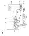
- Fig. 1 shows an arrangement example of a printer 10 according to an embodiment of the present invention.
- the printer 10 is an inkjet printer which conducts multi-color printing with eight colors or four colors by changing the number of colors according to a command from a user and comprises a cartridge retainer 12, a connector 14, a plurality of ink supply passages 16-1a through 16-4b, a print head 18, and a control circuit 20.
- the cartridge retainer 12 retains a plurality of ink cartridges 104 used for printing.
- the cartridge retainer 12 retains four cartridge groups 102-1 through 102-4 each having two ink cartridges 104a and 104b, thereby retaining eight ink cartridges 104 in total.
- the eight ink cartridges 104 retained by the cartridge retainer 12 contain different color inks, respectively, so that the cartridge retainer 12 retains eight ink cartridges 104 of different colors.
- the two ink cartridges 104a, 104b of each of the cartridge groups 102-1 through 102-4 retained by the cartridge retainer 12 contain same color ink so that the cartridge retainer 12 retains two ink cartridges 104a, 104b for each color.
- the ink cartridge 104a of each cartridge group 102 is an example of a first ink cartridge.
- the ink cartridge 104b is an example of a second ink cartridge.
- the cartridge retainer 12 retains the respective ink cartridges 104a, 104b for every cartridge group 102 so that the cartridge retainer 12 retains the same number of pairs of the first and second ink cartridges as the number of the cartridge groups 102.
- each ink cartridge 104a, 104b is provided with an ink end sensor 106 and a cartridge detection sensor 108.
- the ink end sensor 106 is a sensor for detecting when the ink in the ink cartridge 104a, 104b is finished up (ink end).
- the cartridge detection sensor 108 is a sensor for detecting whether or not the ink cartridge 104a, 104b is retained by the cartridge retainer 12.
- the connector 14 connects the ink cartridges 104a, 104b of the cartridge groups 102-1 through 102-4 to the eight ink supply passages 16-la through 16-4b.
- the eight ink supply passages 16-1a through 16-4b supply inks supplied from the ink cartridges 104a, 104b to the print head 18 via the connector 14.
- the eight ink supply passages 16-1a through 16-4b are disposed corresponding to eight ink cartridges 104 retained by the cartridge retainer 12, respectively.
- the ink supply passages 16-1a through 16-4b are connected via the connector 14 to the corresponding ink cartridges 104a, 104b, respectively.
- each pair of the ink supply passages 16-1a through 16-4b are connected via the connector 14 to either of the ink cartridges 104a, 104b in the cartridge group 102 for the corresponding ink cartridges 104a, 104b.
- the print head 18 is an inkjet head for ejecting ink droplets.
- the print head 18 has eight nozzle arrays 202-la through 202-4b corresponding to the respective ink cartridges 104 retained by the cartridge retainer 12.
- the nozzle arrays 202-1a through 202-4a are examples of first nozzle arrays and correspond to the respective ink cartridges 104a of the cartridge groups 102-1 through 102-4.
- the nozzle arrays 202-1b through 202-4b are examples of second nozzle arrays and correspond to the respective ink cartridges 104b of the cartridge groups 102-1 through 102-4.
- Each of the nozzle arrays 202-1a through 202-4b is a nozzle array including one or more nozzles which eject ink droplets according to a command of the control circuit 20.
- the nozzle arrays 202-1a through 202-4b are connected to the ink supply passages 16-1 a through 16-4b, respectively. Therefore, inks are supplied to the nozzle arrays 202-1a through 202-4b from the ink cartridges 104 via the ink supply passages 16-1a through 16-4b and the connector 14.
- the control circuit 20 controls the operation of the printer 10.
- the control circuit 20 detects presence or absence of the respective ink cartridges 104a, 104b and an ink end according to the outputs from the cartridge detection sensors 108 and the ink end sensors 106 of the respective ink cartridges 104a, 104b. Then, according to the detection results, the control circuit 20 controls the operations of the connector 14 and the print head 18.
- Fig. 2 shows an example of the detailed structure of main parts of the printer 10.
- the connector 14 has valves 302a, 302b and a valve 304 for each of the cartridge groups 102-1 through 102-4.
- the valves 302a, 302b are automatic valves which open or close according to an output signal from a valve control section 402 in the control circuit 20.
- the valve 302a is an example of a first cartridge connecting valve and is connected to the ink cartridge 104a of the corresponding cartridge group 102.
- the valve 302b is an example of a second cartridge connecting valve and is connected to the ink cartridge 104b of the corresponding cartridge group 102.
- the valves 302a, 302b are connected, at the sides opposite to the ink cartridges 104a, 104b, to the ink supply passages 16 corresponding to the ink cartridges 104a, 104b.
- the valves 302a, 302b corresponding to the ink cartridges 104a, 104b of the cartridge group 102-1 are connected to the ink supply passages 16-1a, 16-1b, respectively.
- the ink supply passages 16-1a through 16-4b connect the valves 302a, 302b corresponding to the respective cartridge groups 102-1 through 102-4 to the respective nozzle arrays 202-1a through 202-4b.
- the ink supply passages 16-1a, 16-1b connect the valves 302a, 302b corresponding to the cartridge group 102-1 to the nozzle arrays 202-1a, 202-1b. Therefore, the ink cartridges 104a, 104b of the cartridge group 102-1 are connected to the nozzle arrays 202-la, 202-1b via the valves 302a, 302b.
- the valve 304 is an example of a connecting passage shut-off device for opening or closing a passage connecting the two ink supply passages 16 respectively connected to the valves 302a, 302b corresponding to the same cartridge group 102.
- the valve 304 corresponding to the cartridge group 102-1 opens or closes a passage connecting the ink supply passage 16-1a and the ink supply passage 16-1b.
- the valve 304 is a manual valve.
- the valve 304 may be an automatic valve which is operated according to an output signal from the valve control section 402.
- the control circuit 20 has the valve control section 402 and a print control section 404.
- the valve control section 402 controls the operation of the valves 302a, 302b corresponding to the respective cartridge groups 102-1 through 102-4.
- the valve control section 402 detects presence or absence of the respective ink cartridges 104a, 104b and an ink end according to the outputs from the cartridge detection sensors 108 and the ink end sensors 106 of the respective ink cartridges 104a, 104b. According to the detection results, the valve control section 402 controls the operation of the respective valves 302a, 302b. Further, the valve control section 402 transmits the detection result of the ink end to the print control section 404.
- the print control section 404 controls the printing operation of the printer 10 by controlling the operation and the like of the print head 18. Based on the detection result of the ink end received from the valve control section 402, the print control section 404 stops the printing operation when ink required for the printing is finished up. '
- the cartridge retainer 12 retains the ink cartridges 104 of eight colors which are different colors from each other as described with regard to Fig. 1 . Therefore, the ink cartridges 104a, 104b in each of the cartridge groups 102-1 through 102-4 contain different color inks.
- the valves 304 are closed, for example, by a user before the start of printing. Therefore, the two ink supply passages 16 (for example, the ink supply passage 16-1a and the ink supply passage 16-1b) corresponding to the same cartridge group 102 become ink supply passages 16 independent from each other.
- valve control section 402 opens both the valves 302a, 302b. Therefore, inks of different colors are supplied to the ink supply passages 16-1a through 16-4b, respectively. The inks of different colors are further supplied to the nozzle arrays 202-1a through 202-4b connected to the ink supply passages 16-la through 16-4b. Accordingly, the multi-color printing with eight colors of which number is equal to the total number of the ink cartridges 104a, 140b retained by the cartridge retainer 12 can be suitably conducted.
- the print control section 404 stops the printing operation when any one of the ink cartridges 104a, 104b gets empty. Accordingly, the printing operation for the multi-color printing with eight colors can be suitably controlled.
- the cartridge retainer 12 retains the ink cartridges 104 of four colors, being different on a cartridge group 102 base. Therefore, the ink cartridges 104a, 104b in each of the cartridge groups 102-1 through 102-4 contain same color ink.
- the valves 304 are opened, for example, by the user before the start of printing.
- the valve control section 402 opens either one of the valves 302a, 302b corresponding to the same cartridge group 102.
- Supplied to the two ink supply passages 16 (for example, the ink supply passages 16-1a, 16-1b) corresponding to the same cartridge group 102 is thus the ink from the ink cartridge 104 connected to the opened one of the valves 302a, 302b. Accordingly, the two ink supply passages 16 corresponding to the same cartridge group 102 become ink supply passages 16 for the same color ink.
- the two nozzle arrays 202 (for example, the nozzle arrays 202-1a, 202-1b) connected to the two ink supply passages 16 is also the same color ink.
- the number of nozzles for each color is twice as much as the case of multi-color printing with eight colors. Therefore, in this case, the printing can be conducted at high speed as compared to the case of multi-color printing with eight colors.
- the valve control section 402 controls the switching between the ink cartridges 104a, 104b to be used. For example, when the valve control section 402 opens the valve 302a first of the valves 302a, 302b, the valve control section 402 closes the valve 302a and opens the valve 302b according to the emptying of the ink cartridge 104a connected to the valve 302a. In this manner, in case that one of the ink cartridges 104a gets empty, the ink cartridge 104 connected to the two ink supply passages 16 can be automatically changed to the other ink cartridge 104b.
- the inks in the respective ink cartridges 104a, 104b can be finished up without waste.
- the switching between the ink cartridges 104a, 104b can be suitably conducted while finishing up the remaining amount of ink without waste.
- the arrangement of this embodiment can be achieved, for example, from a conventional printer without significant changes. That is, the function for switching the ink cartridges 104a, 104b can be achieved with just a little increase of cost. Furthermore, it also enables the printer 10, which can suitably prevent interruption of printing due to the ink end, to be manufactured at a low cost.
- the print control section 404 does not stop the printing operation when only one of the two ink cartridges 104a, 104b in the same cartridge group 102 gets empty and stops the printing operation when both the two ink cartridges 104a, 104b get empty. In this manner, the print control section 404 can suitably control the printing operation according to the number of colors of inks. Further, in case of multi-color printing with four colors, the switching between the ink cartridges 104a, 104b can be suitably conducted.
- the printer 10 is preferably provided with a display for displaying the state of ink end of the selected ink cartridge 104 or the states of ink end of the respective ink cartridges 104.
- the selected ink cartridge 104 means the ink cartridge 104 of which the corresponding valve 302a or 302b is opened.
- the display may be an LED display. Further, the display may be disposed on each ink cartridge 104.
- this arrangement can suitably display which ink cartridge 104 is in use and display the ink end of each ink cartridge 104. This assists the user to suitably replace or refill the ink cartridge 104.
- the print control section 404 preferably notify the user of the empty of the ink cartridge 104 while continuing the printing operation. This notification may be conducted by the aforementioned display. In this manner, the ink cartridge 104 can be suitably replaced or refilled even during the image formation without interrupting the printing operation.
- the printer 10 can print with only ink cartridges 104a, 104b which are attached.
- the print control section 404 and the valve control section 402 treat the ink cartridge 104, which is not attached, the same as the empty ink cartridge 104, for example, to conduct the respective controls.
- the ratio of the maximum quantity of printable colors to the quantity of limited colors in the printer 10 is not limited to twice and may be more than twice.
- at least some cartridge groups 102 each have three or more ink cartridges 104.
- the ink cartridges 104 in the same cartridge group 102 may contain different color inks or same color ink according to the number of colors for multi-color printing. For printing with limited number of colors, the ink cartridges 104 in the same cartridge group 102 are switched to be sequentially used.
- the present invention can be suitably used in a printer, for example.
Landscapes
- Ink Jet (AREA)
- Particle Formation And Scattering Control In Inkjet Printers (AREA)
- Massaging Devices (AREA)
Applications Claiming Priority (1)
| Application Number | Priority Date | Filing Date | Title |
|---|---|---|---|
| JP2007029021A JP2008194826A (ja) | 2007-02-08 | 2007-02-08 | 印刷装置 |
Publications (2)
| Publication Number | Publication Date |
|---|---|
| EP1955853A1 true EP1955853A1 (de) | 2008-08-13 |
| EP1955853B1 EP1955853B1 (de) | 2010-04-07 |
Family
ID=39321520
Family Applications (1)
| Application Number | Title | Priority Date | Filing Date |
|---|---|---|---|
| EP08290001A Active EP1955853B1 (de) | 2007-02-08 | 2008-01-02 | Drucker |
Country Status (7)
| Country | Link |
|---|---|
| US (1) | US7971946B2 (de) |
| EP (1) | EP1955853B1 (de) |
| JP (1) | JP2008194826A (de) |
| KR (1) | KR101350880B1 (de) |
| CN (1) | CN101239534B (de) |
| AT (1) | ATE463350T1 (de) |
| DE (1) | DE602008000903D1 (de) |
Cited By (1)
| Publication number | Priority date | Publication date | Assignee | Title |
|---|---|---|---|---|
| EP3733417A1 (de) * | 2019-05-02 | 2020-11-04 | Artech GmbH design + production in plastic | Tintenzuführung und testdrucksystem |
Families Citing this family (16)
| Publication number | Priority date | Publication date | Assignee | Title |
|---|---|---|---|---|
| KR200455856Y1 (ko) * | 2008-11-27 | 2011-09-29 | 마카스아이(주) | 대형 프린터의 카트리지 제어장치 |
| JPWO2010082296A1 (ja) * | 2009-01-13 | 2012-06-28 | 株式会社ミマキエンジニアリング | バルクインク供給システム |
| US9061515B2 (en) | 2011-04-04 | 2015-06-23 | Hewlett-Packard Development Company, L.P. | Fluid supply systems, methods, and articles of manufacture |
| JP6003034B2 (ja) * | 2011-09-20 | 2016-10-05 | セイコーエプソン株式会社 | 液体吐出装置、及び、液体循環方法 |
| JP5796458B2 (ja) * | 2011-11-07 | 2015-10-21 | セイコーエプソン株式会社 | 液体吐出装置、及び、液体循環方法 |
| JP5796459B2 (ja) * | 2011-11-07 | 2015-10-21 | セイコーエプソン株式会社 | 印刷装置、及び、ホワイトインク循環方法 |
| JP5938891B2 (ja) | 2011-12-20 | 2016-06-22 | セイコーエプソン株式会社 | 印刷装置、及び、液体移送方法 |
| JP6390444B2 (ja) | 2015-01-21 | 2018-09-19 | ブラザー工業株式会社 | インクジェット記録装置、及びプログラム |
| JP6428293B2 (ja) | 2015-01-21 | 2018-11-28 | ブラザー工業株式会社 | インクジェット記録装置、及びプログラム |
| US9623691B2 (en) | 2015-01-21 | 2017-04-18 | Brother Kogyo Kabushiki Kaisha | Inkjet recording apparatus with cover and method therefor including inquiry and notification features |
| JP6557978B2 (ja) | 2015-01-21 | 2019-08-14 | ブラザー工業株式会社 | インクジェット記録装置、及びプログラム |
| CN107206801B (zh) * | 2015-01-30 | 2018-11-02 | 惠普发展公司,有限责任合伙企业 | 用于打印流体供应系统的阀门 |
| JP6935718B2 (ja) * | 2017-10-11 | 2021-09-15 | セイコーエプソン株式会社 | 液体吐出装置、その製造方法およびメンテナンス方法 |
| JP7246964B2 (ja) * | 2019-02-20 | 2023-03-28 | ローランドディー.ジー.株式会社 | インクジェットプリンタおよび検出方法 |
| CN111013853A (zh) * | 2020-01-15 | 2020-04-17 | 台州路桥南瑞智能装备科技有限公司 | 一种金属表面彩色喷涂设备 |
| CN119261372B (zh) * | 2023-07-04 | 2025-11-18 | 深圳市汉森软件股份有限公司 | 纯色转印打印方法、装置、设备及存储介质 |
Citations (2)
| Publication number | Priority date | Publication date | Assignee | Title |
|---|---|---|---|---|
| US4833491A (en) * | 1988-06-15 | 1989-05-23 | Xerox Corporation | Thermal ink jet printer adapted to operate in monochrome, highlight or process color modes |
| JP2004098365A (ja) | 2002-09-06 | 2004-04-02 | Mimaki Engineering Co Ltd | インクジェットプリンタ用のインク供給機構 |
Family Cites Families (8)
| Publication number | Priority date | Publication date | Assignee | Title |
|---|---|---|---|---|
| DE3446998A1 (de) * | 1983-12-26 | 1985-07-04 | Canon K.K., Tokio/Tokyo | Tintenstrahl-aufzeichnungsgeraet |
| JP2859236B2 (ja) * | 1996-12-26 | 1999-02-17 | 新潟日本電気株式会社 | 静電式インクジェット記録装置 |
| US6082851A (en) * | 1997-11-14 | 2000-07-04 | Canon Kabushiki Kaisha | Liquid ejection printing apparatus and liquid supply method to be employed in the same |
| ATE461043T1 (de) * | 1999-11-05 | 2010-04-15 | Seiko Epson Corp | Aufzeichnungsgerät des tintenstrahltyps und verfahren zur tintenversorgung für den untertank mittels desselben gertes und verfahren zur kontrolle der dem untertank zugeführten tintenmenge mittels desselben gerätes |
| ATE402017T1 (de) * | 2001-02-09 | 2008-08-15 | Seiko Epson Corp | Tintenstrahlaufzeichnungsvorrichtung, steuerungs- und tintennachfüllsverfahren in der vorrichtung ausgeführt, tintenversorgungssystem in der vorrichtung, und verwaltungsverfahren der von dem system versorgt tintenmenge |
| KR100387551B1 (en) * | 2002-03-12 | 2003-06-18 | Hanlim | Ink feeding device for large ink jet printer |
| CN2573231Y (zh) * | 2002-09-24 | 2003-09-17 | 缪则夫 | 喷墨打印机可持续供墨装置 |
| US7850290B2 (en) * | 2006-12-28 | 2010-12-14 | Toshiba Tec Kabushiki Kaisha | Ink jet recording apparatus, ink supplying mechanism and ink supplying method |
-
2007
- 2007-02-08 JP JP2007029021A patent/JP2008194826A/ja active Pending
- 2007-08-20 KR KR1020070083402A patent/KR101350880B1/ko not_active Expired - Fee Related
- 2007-10-22 CN CN2007101634201A patent/CN101239534B/zh active Active
-
2008
- 2008-01-02 DE DE602008000903T patent/DE602008000903D1/de active Active
- 2008-01-02 EP EP08290001A patent/EP1955853B1/de active Active
- 2008-01-02 AT AT08290001T patent/ATE463350T1/de not_active IP Right Cessation
- 2008-02-07 US US12/027,351 patent/US7971946B2/en active Active
Patent Citations (2)
| Publication number | Priority date | Publication date | Assignee | Title |
|---|---|---|---|---|
| US4833491A (en) * | 1988-06-15 | 1989-05-23 | Xerox Corporation | Thermal ink jet printer adapted to operate in monochrome, highlight or process color modes |
| JP2004098365A (ja) | 2002-09-06 | 2004-04-02 | Mimaki Engineering Co Ltd | インクジェットプリンタ用のインク供給機構 |
Cited By (1)
| Publication number | Priority date | Publication date | Assignee | Title |
|---|---|---|---|---|
| EP3733417A1 (de) * | 2019-05-02 | 2020-11-04 | Artech GmbH design + production in plastic | Tintenzuführung und testdrucksystem |
Also Published As
| Publication number | Publication date |
|---|---|
| US7971946B2 (en) | 2011-07-05 |
| KR101350880B1 (ko) | 2014-01-13 |
| US20090315927A1 (en) | 2009-12-24 |
| DE602008000903D1 (de) | 2010-05-20 |
| KR20080074690A (ko) | 2008-08-13 |
| EP1955853B1 (de) | 2010-04-07 |
| ATE463350T1 (de) | 2010-04-15 |
| JP2008194826A (ja) | 2008-08-28 |
| CN101239534A (zh) | 2008-08-13 |
| CN101239534B (zh) | 2010-06-02 |
Similar Documents
| Publication | Publication Date | Title |
|---|---|---|
| EP1955853B1 (de) | Drucker | |
| EP1870241B1 (de) | Bilderzeugungsvorrichtung und Ansteuerverfahren dafür | |
| US8083311B2 (en) | Ink-jet printing apparatus, control method therefor, program, and storage medium | |
| US20180162138A1 (en) | Fluid ejection device and control method therefor | |
| US8398189B2 (en) | Liquid discharge apparatus | |
| JP2002029041A (ja) | インクジェットプリンタ | |
| US20200307239A1 (en) | Droplet discharge apparatus | |
| US7654657B2 (en) | Liquid ejecting apparatus | |
| US20110050796A1 (en) | Liquid jetting apparatus | |
| US20090058908A1 (en) | Liquid jetting apparatus and maintenance method of the liquid jetting apparatus | |
| JP2001187458A (ja) | インクジェット記録装置および印字ヘッドへのインク供給方法 | |
| JP2008006657A (ja) | インクジェット記録装置の液交換方法及びインクジェット記録装置 | |
| JP5839265B2 (ja) | 画像形成装置 | |
| US20200307244A1 (en) | Droplet discharge apparatus | |
| JP2014080008A (ja) | 印刷装置および液体供給方法 | |
| CN102529453B (zh) | 液体喷射头的控制装置及控制方法、液体喷射装置 | |
| US7992960B2 (en) | Non-user-initiated preventative maintenace modes for inkjet-printing device | |
| JP2009113412A (ja) | インクジェットプリンタ | |
| JPH0229345A (ja) | インクジェット記録装置 | |
| CN102189809B (zh) | 液体喷射装置 | |
| JP7666123B2 (ja) | 液体供給装置、液体吐出装置及び液体吐出装置の制御方法 | |
| JP4930686B2 (ja) | 記録装置、記録装置の制御方法 | |
| JP2008234313A (ja) | 印刷システム、印刷制御装置及び印刷用紙設定画面の表示方法 | |
| JP2007098746A (ja) | プリンタと印刷システム | |
| US8414106B2 (en) | Printer fluid change manifold |
Legal Events
| Date | Code | Title | Description |
|---|---|---|---|
| PUAI | Public reference made under article 153(3) epc to a published international application that has entered the european phase |
Free format text: ORIGINAL CODE: 0009012 |
|
| 17P | Request for examination filed |
Effective date: 20080102 |
|
| AK | Designated contracting states |
Kind code of ref document: A1 Designated state(s): AT BE BG CH CY CZ DE DK EE ES FI FR GB GR HR HU IE IS IT LI LT LU LV MC MT NL NO PL PT RO SE SI SK TR |
|
| AX | Request for extension of the european patent |
Extension state: AL BA MK RS |
|
| 17Q | First examination report despatched |
Effective date: 20080925 |
|
| AKX | Designation fees paid |
Designated state(s): AT BE BG CH CY CZ DE DK EE ES FI FR GB GR HR HU IE IS IT LI LT LU LV MC MT NL NO PL PT RO SE SI SK TR |
|
| GRAP | Despatch of communication of intention to grant a patent |
Free format text: ORIGINAL CODE: EPIDOSNIGR1 |
|
| GRAS | Grant fee paid |
Free format text: ORIGINAL CODE: EPIDOSNIGR3 |
|
| GRAA | (expected) grant |
Free format text: ORIGINAL CODE: 0009210 |
|
| AK | Designated contracting states |
Kind code of ref document: B1 Designated state(s): AT BE BG CH CY CZ DE DK EE ES FI FR GB GR HR HU IE IS IT LI LT LU LV MC MT NL NO PL PT RO SE SI SK TR |
|
| REG | Reference to a national code |
Ref country code: GB Ref legal event code: FG4D |
|
| REG | Reference to a national code |
Ref country code: CH Ref legal event code: EP |
|
| REG | Reference to a national code |
Ref country code: IE Ref legal event code: FG4D |
|
| REF | Corresponds to: |
Ref document number: 602008000903 Country of ref document: DE Date of ref document: 20100520 Kind code of ref document: P |
|
| REG | Reference to a national code |
Ref country code: NL Ref legal event code: VDEP Effective date: 20100407 |
|
| PG25 | Lapsed in a contracting state [announced via postgrant information from national office to epo] |
Ref country code: SI Free format text: LAPSE BECAUSE OF FAILURE TO SUBMIT A TRANSLATION OF THE DESCRIPTION OR TO PAY THE FEE WITHIN THE PRESCRIBED TIME-LIMIT Effective date: 20100407 |
|
| LTIE | Lt: invalidation of european patent or patent extension |
Effective date: 20100407 |
|
| PG25 | Lapsed in a contracting state [announced via postgrant information from national office to epo] |
Ref country code: NL Free format text: LAPSE BECAUSE OF FAILURE TO SUBMIT A TRANSLATION OF THE DESCRIPTION OR TO PAY THE FEE WITHIN THE PRESCRIBED TIME-LIMIT Effective date: 20100407 Ref country code: NO Free format text: LAPSE BECAUSE OF FAILURE TO SUBMIT A TRANSLATION OF THE DESCRIPTION OR TO PAY THE FEE WITHIN THE PRESCRIBED TIME-LIMIT Effective date: 20100707 Ref country code: LT Free format text: LAPSE BECAUSE OF FAILURE TO SUBMIT A TRANSLATION OF THE DESCRIPTION OR TO PAY THE FEE WITHIN THE PRESCRIBED TIME-LIMIT Effective date: 20100407 Ref country code: ES Free format text: LAPSE BECAUSE OF FAILURE TO SUBMIT A TRANSLATION OF THE DESCRIPTION OR TO PAY THE FEE WITHIN THE PRESCRIBED TIME-LIMIT Effective date: 20100718 Ref country code: SE Free format text: LAPSE BECAUSE OF FAILURE TO SUBMIT A TRANSLATION OF THE DESCRIPTION OR TO PAY THE FEE WITHIN THE PRESCRIBED TIME-LIMIT Effective date: 20100407 |
|
| PG25 | Lapsed in a contracting state [announced via postgrant information from national office to epo] |
Ref country code: FI Free format text: LAPSE BECAUSE OF FAILURE TO SUBMIT A TRANSLATION OF THE DESCRIPTION OR TO PAY THE FEE WITHIN THE PRESCRIBED TIME-LIMIT Effective date: 20100407 Ref country code: LV Free format text: LAPSE BECAUSE OF FAILURE TO SUBMIT A TRANSLATION OF THE DESCRIPTION OR TO PAY THE FEE WITHIN THE PRESCRIBED TIME-LIMIT Effective date: 20100407 Ref country code: IS Free format text: LAPSE BECAUSE OF FAILURE TO SUBMIT A TRANSLATION OF THE DESCRIPTION OR TO PAY THE FEE WITHIN THE PRESCRIBED TIME-LIMIT Effective date: 20100807 Ref country code: HR Free format text: LAPSE BECAUSE OF FAILURE TO SUBMIT A TRANSLATION OF THE DESCRIPTION OR TO PAY THE FEE WITHIN THE PRESCRIBED TIME-LIMIT Effective date: 20100407 Ref country code: AT Free format text: LAPSE BECAUSE OF FAILURE TO SUBMIT A TRANSLATION OF THE DESCRIPTION OR TO PAY THE FEE WITHIN THE PRESCRIBED TIME-LIMIT Effective date: 20100407 |
|
| PG25 | Lapsed in a contracting state [announced via postgrant information from national office to epo] |
Ref country code: CY Free format text: LAPSE BECAUSE OF FAILURE TO SUBMIT A TRANSLATION OF THE DESCRIPTION OR TO PAY THE FEE WITHIN THE PRESCRIBED TIME-LIMIT Effective date: 20100602 Ref country code: PL Free format text: LAPSE BECAUSE OF FAILURE TO SUBMIT A TRANSLATION OF THE DESCRIPTION OR TO PAY THE FEE WITHIN THE PRESCRIBED TIME-LIMIT Effective date: 20100407 |
|
| PG25 | Lapsed in a contracting state [announced via postgrant information from national office to epo] |
Ref country code: DK Free format text: LAPSE BECAUSE OF FAILURE TO SUBMIT A TRANSLATION OF THE DESCRIPTION OR TO PAY THE FEE WITHIN THE PRESCRIBED TIME-LIMIT Effective date: 20100407 Ref country code: EE Free format text: LAPSE BECAUSE OF FAILURE TO SUBMIT A TRANSLATION OF THE DESCRIPTION OR TO PAY THE FEE WITHIN THE PRESCRIBED TIME-LIMIT Effective date: 20100407 |
|
| PLBE | No opposition filed within time limit |
Free format text: ORIGINAL CODE: 0009261 |
|
| STAA | Information on the status of an ep patent application or granted ep patent |
Free format text: STATUS: NO OPPOSITION FILED WITHIN TIME LIMIT |
|
| PG25 | Lapsed in a contracting state [announced via postgrant information from national office to epo] |
Ref country code: RO Free format text: LAPSE BECAUSE OF FAILURE TO SUBMIT A TRANSLATION OF THE DESCRIPTION OR TO PAY THE FEE WITHIN THE PRESCRIBED TIME-LIMIT Effective date: 20100407 Ref country code: SK Free format text: LAPSE BECAUSE OF FAILURE TO SUBMIT A TRANSLATION OF THE DESCRIPTION OR TO PAY THE FEE WITHIN THE PRESCRIBED TIME-LIMIT Effective date: 20100407 Ref country code: BE Free format text: LAPSE BECAUSE OF FAILURE TO SUBMIT A TRANSLATION OF THE DESCRIPTION OR TO PAY THE FEE WITHIN THE PRESCRIBED TIME-LIMIT Effective date: 20100407 Ref country code: CZ Free format text: LAPSE BECAUSE OF FAILURE TO SUBMIT A TRANSLATION OF THE DESCRIPTION OR TO PAY THE FEE WITHIN THE PRESCRIBED TIME-LIMIT Effective date: 20100407 |
|
| 26N | No opposition filed |
Effective date: 20110110 |
|
| PG25 | Lapsed in a contracting state [announced via postgrant information from national office to epo] |
Ref country code: GR Free format text: LAPSE BECAUSE OF FAILURE TO SUBMIT A TRANSLATION OF THE DESCRIPTION OR TO PAY THE FEE WITHIN THE PRESCRIBED TIME-LIMIT Effective date: 20100708 |
|
| PG25 | Lapsed in a contracting state [announced via postgrant information from national office to epo] |
Ref country code: MC Free format text: LAPSE BECAUSE OF NON-PAYMENT OF DUE FEES Effective date: 20110131 |
|
| REG | Reference to a national code |
Ref country code: IE Ref legal event code: MM4A |
|
| PG25 | Lapsed in a contracting state [announced via postgrant information from national office to epo] |
Ref country code: MT Free format text: LAPSE BECAUSE OF FAILURE TO SUBMIT A TRANSLATION OF THE DESCRIPTION OR TO PAY THE FEE WITHIN THE PRESCRIBED TIME-LIMIT Effective date: 20100407 |
|
| PG25 | Lapsed in a contracting state [announced via postgrant information from national office to epo] |
Ref country code: IE Free format text: LAPSE BECAUSE OF NON-PAYMENT OF DUE FEES Effective date: 20110102 |
|
| REG | Reference to a national code |
Ref country code: CH Ref legal event code: PL |
|
| PG25 | Lapsed in a contracting state [announced via postgrant information from national office to epo] |
Ref country code: LI Free format text: LAPSE BECAUSE OF NON-PAYMENT OF DUE FEES Effective date: 20120131 Ref country code: CH Free format text: LAPSE BECAUSE OF NON-PAYMENT OF DUE FEES Effective date: 20120131 |
|
| PG25 | Lapsed in a contracting state [announced via postgrant information from national office to epo] |
Ref country code: LU Free format text: LAPSE BECAUSE OF NON-PAYMENT OF DUE FEES Effective date: 20110102 |
|
| PG25 | Lapsed in a contracting state [announced via postgrant information from national office to epo] |
Ref country code: PT Free format text: LAPSE BECAUSE OF NON-PAYMENT OF DUE FEES Effective date: 20100407 |
|
| PG25 | Lapsed in a contracting state [announced via postgrant information from national office to epo] |
Ref country code: TR Free format text: LAPSE BECAUSE OF FAILURE TO SUBMIT A TRANSLATION OF THE DESCRIPTION OR TO PAY THE FEE WITHIN THE PRESCRIBED TIME-LIMIT Effective date: 20100407 Ref country code: BG Free format text: LAPSE BECAUSE OF FAILURE TO SUBMIT A TRANSLATION OF THE DESCRIPTION OR TO PAY THE FEE WITHIN THE PRESCRIBED TIME-LIMIT Effective date: 20100707 |
|
| PG25 | Lapsed in a contracting state [announced via postgrant information from national office to epo] |
Ref country code: HU Free format text: LAPSE BECAUSE OF FAILURE TO SUBMIT A TRANSLATION OF THE DESCRIPTION OR TO PAY THE FEE WITHIN THE PRESCRIBED TIME-LIMIT Effective date: 20100407 |
|
| REG | Reference to a national code |
Ref country code: FR Ref legal event code: PLFP Year of fee payment: 9 |
|
| REG | Reference to a national code |
Ref country code: FR Ref legal event code: PLFP Year of fee payment: 10 |
|
| REG | Reference to a national code |
Ref country code: FR Ref legal event code: PLFP Year of fee payment: 11 |
|
| PGFP | Annual fee paid to national office [announced via postgrant information from national office to epo] |
Ref country code: FR Payment date: 20171211 Year of fee payment: 11 |
|
| PGFP | Annual fee paid to national office [announced via postgrant information from national office to epo] |
Ref country code: GB Payment date: 20171227 Year of fee payment: 11 |
|
| PGFP | Annual fee paid to national office [announced via postgrant information from national office to epo] |
Ref country code: IT Payment date: 20180122 Year of fee payment: 11 |
|
| GBPC | Gb: european patent ceased through non-payment of renewal fee |
Effective date: 20190102 |
|
| PG25 | Lapsed in a contracting state [announced via postgrant information from national office to epo] |
Ref country code: FR Free format text: LAPSE BECAUSE OF NON-PAYMENT OF DUE FEES Effective date: 20190131 |
|
| PG25 | Lapsed in a contracting state [announced via postgrant information from national office to epo] |
Ref country code: GB Free format text: LAPSE BECAUSE OF NON-PAYMENT OF DUE FEES Effective date: 20190102 |
|
| PG25 | Lapsed in a contracting state [announced via postgrant information from national office to epo] |
Ref country code: IT Free format text: LAPSE BECAUSE OF NON-PAYMENT OF DUE FEES Effective date: 20190102 |
|
| PGFP | Annual fee paid to national office [announced via postgrant information from national office to epo] |
Ref country code: DE Payment date: 20241203 Year of fee payment: 18 |