EP1955866A1 - Dispositif de collage de matériaux en feuilles - Google Patents
Dispositif de collage de matériaux en feuilles Download PDFInfo
- Publication number
- EP1955866A1 EP1955866A1 EP07123021A EP07123021A EP1955866A1 EP 1955866 A1 EP1955866 A1 EP 1955866A1 EP 07123021 A EP07123021 A EP 07123021A EP 07123021 A EP07123021 A EP 07123021A EP 1955866 A1 EP1955866 A1 EP 1955866A1
- Authority
- EP
- European Patent Office
- Prior art keywords
- sheet
- transport drum
- transport
- drum
- delivery table
- Prior art date
- Legal status (The legal status is an assumption and is not a legal conclusion. Google has not performed a legal analysis and makes no representation as to the accuracy of the status listed.)
- Withdrawn
Links
- 238000004026 adhesive bonding Methods 0.000 title claims description 27
- 239000000463 material Substances 0.000 title claims description 9
- 239000011248 coating agent Substances 0.000 claims abstract description 3
- 238000000576 coating method Methods 0.000 claims abstract description 3
- 239000003292 glue Substances 0.000 claims description 38
- 230000033001 locomotion Effects 0.000 claims description 29
- 238000003860 storage Methods 0.000 claims description 15
- 239000004831 Hot glue Substances 0.000 claims description 12
- 230000001360 synchronised effect Effects 0.000 claims description 6
- 239000000853 adhesive Substances 0.000 abstract 2
- 230000001070 adhesive effect Effects 0.000 abstract 2
- 230000032258 transport Effects 0.000 description 68
- 238000000034 method Methods 0.000 description 9
- 238000004519 manufacturing process Methods 0.000 description 7
- 238000012545 processing Methods 0.000 description 4
- 230000008569 process Effects 0.000 description 3
- 238000011161 development Methods 0.000 description 2
- 230000018109 developmental process Effects 0.000 description 2
- 238000012546 transfer Methods 0.000 description 2
- 230000004913 activation Effects 0.000 description 1
- 230000004888 barrier function Effects 0.000 description 1
- 238000004140 cleaning Methods 0.000 description 1
- 238000011109 contamination Methods 0.000 description 1
- 230000009849 deactivation Effects 0.000 description 1
- 230000001419 dependent effect Effects 0.000 description 1
- 230000000994 depressogenic effect Effects 0.000 description 1
- 238000013461 design Methods 0.000 description 1
- 238000010586 diagram Methods 0.000 description 1
- 239000000284 extract Substances 0.000 description 1
- 238000009434 installation Methods 0.000 description 1
- 239000007788 liquid Substances 0.000 description 1
- 230000002093 peripheral effect Effects 0.000 description 1
- 238000012549 training Methods 0.000 description 1
Images


Classifications
-
- B—PERFORMING OPERATIONS; TRANSPORTING
- B42—BOOKBINDING; ALBUMS; FILES; SPECIAL PRINTED MATTER
- B42C—BOOKBINDING
- B42C9/00—Applying glue or adhesive peculiar to bookbinding
- B42C9/0081—Applying glue or adhesive peculiar to bookbinding applying adhesive to individual sheets for binding them together
-
- B—PERFORMING OPERATIONS; TRANSPORTING
- B65—CONVEYING; PACKING; STORING; HANDLING THIN OR FILAMENTARY MATERIAL
- B65H—HANDLING THIN OR FILAMENTARY MATERIAL, e.g. SHEETS, WEBS, CABLES
- B65H3/00—Separating articles from piles
- B65H3/08—Separating articles from piles using pneumatic force
- B65H3/0808—Suction grippers
- B65H3/085—Suction grippers separating from the bottom of pile
-
- B—PERFORMING OPERATIONS; TRANSPORTING
- B65—CONVEYING; PACKING; STORING; HANDLING THIN OR FILAMENTARY MATERIAL
- B65H—HANDLING THIN OR FILAMENTARY MATERIAL, e.g. SHEETS, WEBS, CABLES
- B65H37/00—Article or web delivery apparatus incorporating devices for performing specified auxiliary operations
- B65H37/04—Article or web delivery apparatus incorporating devices for performing specified auxiliary operations for securing together articles or webs, e.g. by adhesive, stitching or stapling
-
- B—PERFORMING OPERATIONS; TRANSPORTING
- B65—CONVEYING; PACKING; STORING; HANDLING THIN OR FILAMENTARY MATERIAL
- B65H—HANDLING THIN OR FILAMENTARY MATERIAL, e.g. SHEETS, WEBS, CABLES
- B65H5/00—Feeding articles separated from piles; Feeding articles to machines
- B65H5/22—Feeding articles separated from piles; Feeding articles to machines by air-blast or suction device
- B65H5/222—Feeding articles separated from piles; Feeding articles to machines by air-blast or suction device by suction devices
- B65H5/226—Feeding articles separated from piles; Feeding articles to machines by air-blast or suction device by suction devices by suction rollers
Definitions
- the invention relates to a device for gluing sheet material according to the preamble of the independent claim.
- photo books With the spread of digital photography so-called photo books are becoming increasingly popular.
- the customer assembles an illustrated book in electronic form by means of suitable software from his present picture material and sends it to a photo lab.
- the individual pages of the book are exposed on photographic support material (photo paper) and developed and then assembled into a photo book.
- the customer can also leave the compilation of the image material (layout) to the photo lab.
- the so-called Leporello method is a well-known bookbinding method, in which folded double sheets are glued together with the image-bearing sides together to form a stack.
- the Leporello process is in principle also advantageous for the production of photo books, but there are still no suitable gluing devices that would meet the usual requirements in the photographic industry.
- the production capacity of the gluing device must be very high, for example, about 4000 book pages per hour corresponding to 100 photo books of 40 pages.
- Another complication arises from the material properties of the photographic paper, because it requires the glueing of a special hot-melt adhesive.
- Known gluing devices are either not set up for the processing of hot-melt adhesives or, by design, do not have the required power capacity.
- the present invention is now an apparatus for gluing sheet material to be created, which is characterized mainly by a high processing performance and is also suitable for processing of hot melt adhesives.
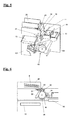
- the apparatus comprises as a central core a rotatably driven transport drum 10 for transporting a sheet along a circular arc-shaped path from a feed position P to a discharge position P2. It further comprises a feed device 20 for feeding a sheet B onto the transport drum 10 in the region of the feed position, holding means 30 for holding a sheet on the drum surface, a pressure roller 35, a gluing unit 40 for coating a sheet on the transport drum 10 with a glue, especially a hot-melt adhesive, a movably driven storage table 50 for glued sheets B and by a motor 60 symbolized drive means for the transport drum 10, the feeder 20, the glue unit 40 and the storage table 50.
- the rotational movement of the transport drum 10 is indicated by the arrow 11.
- the feed device 20 comprises a suction bar 21 arranged on a pivotable drive lever 22 and a transport roller pair 23.
- the drive lever 22 is in contact with a motor-driven cam 25 (FIG. Fig. 6 ) and moves the squeegee 21 on the pair of transport rollers 23 to and again away from this, as indicated by the arrow 24.
- the suction strip 21 comprises a number of suction openings, not shown, which are connected to a suction pump, also not shown.
- the row of suction openings extends substantially parallel to the axis of the transport drum 10, in the Fig. 1 ie perpendicular to the drawing plane.
- the suction strip 21 is located below a supply magazine 26 (FIG. Fig. 6 ) for sheets to be glued B and detects the sheet B lying there or the lowest sheet of a sheet stack located in the supply magazine. This is done by a short vertical Lifting movement achieved.
- the means for generating this lifting movement can be, for example, pneumatic and are in the Fig. 1 for the sake of clarity not shown.
- the holding means 30 in the transport drum 10 hold the abandoned sheet in the region of the leading edge.
- the holding means 30 comprise similar to the suction strip 21 an axially parallel row of suction ports 31 which are connected to a suction pump 32. When placing a sheet on the transport drum 10, this is in a rotational position in which the suction openings 31 are in the region of the feed position P1, so that the leading edge of the abandoned sheet is held.
- the transport drum 10 is recessed sector-shaped in front of the holding means 30 and the suction openings 31, whereby a rebounding, approximately radially extending stop wall 14 is formed.
- the sheets B are first roughly deposited by the feed device 20 such that their leading edge or folded edge B V protrudes beyond the positioning edge formed by the abutment wall 14 and the drum periphery ( Fig. 14a ).
- the positioning edge forms a reference position for the leading edge B V of the leaves B.
- a sunk in the sector-shaped recess 13 of the transport drum 10 arranged stop flap 15 is raised radially outwardly and folded against the stop wall 14. there the sheet edge is pushed back from the stopper flap 15 to the positioning edge and thus the sheet B is positioned exactly ( Fig.
- the stopper flap 16 is again in their in Fig. 14a moved back home position shown.
- the movement of the stop flap 15 is synchronized with the rotational movement of the transport drum 10, which may be realized for example by suitably shaped mechanical scenes or pneumatic means.
- the sheet placed and positioned on the transport drum 10 is now moved by the rotating transport drum 10 through the glue unit 40 into the delivery position P2.
- the pinch roller 35 additionally holds the sheet firmly on the drum surface.
- the glue unit 40 comprises a reservoir 41 filled with a hot-melt adhesive with a heater 42 in order to keep the hot-melt adhesive at the required working temperature.
- a scoop roller 43 dips into the liquid hot-melt adhesive and transfers it to a glue application roller 44. The latter finally coats the sheet passing by on the transport drum 10 with a thin layer of hot-melt adhesive.
- the glue application roller 44 is, as indicated by the arrow 45, mounted pivotably about the scoop roller 43, so that it can be lifted off the transport drum 10 or returned to it.
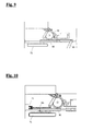
- pneumatic adjusting provided, which are driven by a sheet detector in the form of a photoelectric barrier 46.
- the sheet detector detects when a sheet is under the glue application roller, and then causes a corresponding adjustment of the glue application roller 44th Die Fig. 3 shows the glue application roller 44 in lifted from the transport drum 10 state.
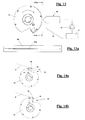
- the gluing unit 40 may alternatively have a glue application nozzle 48 instead of the glue application roller, as shown in FIGS Figures 13 and 13a is shown.
- the glue application nozzle 48 is fed from the reservoir 41 via a feed pump 47.
- the glue application nozzle 48 has an elongate nozzle slot 48a, which is arranged parallel to a surface line of the transport drum 10 analogously to the glue application roller is.
- the sheet detector 46 is used analogously to control the activation / deactivation of the glue application nozzle 48, so that glue is applied only when a sheet is in the region of the glue application nozzle on the transport drum.
- the glue application nozzle 48 may be designed such that it can be pivoted away from the transport drum 10 for cleaning purposes.
- the nozzle slot 48a can also be divided into several sections, wherein then depending on the sheet width only the corresponding number of sections is activated.
- a very essential part of the inventive device is the storage table 50.
- This is, as the two arrows 51 and 52 indicate, driven in two mutually perpendicular directions movable and thereby passes through the following cycle of motion: raising to the level of the transport drum 10, horizontal movement of the Transport drum passing substantially in the tangential plane 12 of the transport drum 10 in the region of the dispensing position P2, lowering and horizontal return movement to the starting position.
- the cycle of movement of the tray table 50 is in strict synchrony with the rotation of the transport drum 10, the latter performing two complete revolutions during a complete cycle of movement. While the tray 50 is in the range of the dispensing position P2, ie during its passage immediately under the transport drum, its speed is exactly the same size as the peripheral speed of the transport drum 10.
- the raising and lowering of the tray is done with conventional, the clarity half pneumatic means, not shown.
- the stacking table 50 On the storage table 50 is a sheet B, with which the sheet located on the transport drum 10 is to be glued.
- the stacking table may also contain a stack of (already glued) sheets, in which case the sheet located on the transport drum is glued to the uppermost sheet of the sheet stack.
- FIGS. 2 and 3 illustrate the actual gluing process.
- the movements of the transport drum 10 and the delivery table 50 are coordinated so that the delivery table reaches the transfer drum at the precise moment when the leading edge of the sheet B located on the transport drum coincides exactly with the leading edge of the (top) sheet located on the delivery table ( Fig. 2 ).
- the tray table 50 which is located on the transport drum sheet B is accurately placed on the sheet on the tray and pressed with this ( Fig. 3 ).
- the sheet carrying the glue layer on the transport drum detaches from this and is deposited on the delivery table.
- the transport drum 10 and the tray table 50 move continuously further into their in Fig. 1 starting positions shown and a new gluing cycle can begin.
- the device shown can be used for the gluing of simple sheet material, for. B. for the production of two-layer postcards.
- the device according to the invention is designed for the production of photobooks according to the already mentioned Leporello method in which folded double sheets are glued together and thus bound to form a book.
- the Fig. 4 clarifies this.
- Each folded double sheet B includes an upper sheet portion Ba and a lower sheet portion Bb.
- the lower sheet portion Bb of a double sheet is respectively bonded to the upper sheet portion Ba of the underlying double sheet.
- the glue layer between the leaf parts is in Fig. 4 denoted by G.
- the individual double sheets are placed in a stack (manually or preferably automatically) in the supply magazine and then placed in order with the leading edge on the transport drum.
- the first double sheet of a photo book to be created is not coated with hot-melt adhesive, but deposited only on the storage table 50. All subsequent double sheets are coated as described above with hot melt adhesive and then glued to the topmost double sheet on the tray.
- FIGS. 5-12 show in a somewhat simplified form a practical realization of the inventive gluing in the application for the production of photobooks by the Leporello method, so that folded double sheets are processed.
- Fig. 5 the individual components are arranged on or between two parallel plates 101 and 102 of a mounting frame. It can be seen on the top of a professional storage magazine 26 for receiving a stack to be processed, folded double sheets, a roller 23 of the transport roller pair, the transport drum 10, the pinch roller 35, the glue unit 40 with the glue application roller 44, the tray 50 and a conveyor 72 in the form a conveyor belt. The latter will be returned further down. Furthermore, in Fig. 5 still different parts of the total designated 60 drive means for the transport drum and other movably driven device components recognizable. From the transport drum 10 projects axially a suction tube 33, which with the suction openings 31 (FIG. Fig. 1 ) in the transport drum 10 and for connection to the suction pump 32 (FIG. Fig. 1 ) serves.
- a double sheet B is transported from the transport drum 10 to the glue application roller 44 and is held by the suction openings 31 in the region of its leading edge on the drum surface.
- a folded double sheet B On the storage table is a folded double sheet B, with which the sheet is to be glued on the transport drum.
- the Fig. 8 corresponds essentially to the sketch of Fig. 2 , It can be seen how the front edge (leading edge) of the double-sheet B on the transport drum coincides with the front edge of the double-sheet B on the delivery table 50.
- Analog corresponds to the Fig. 9 essentially the sketch of the Fig. 3 ,
- the tray table 50 moves under the transport drum 10 and is pushed up.
- the glued sheet is rolled up onto the sheet located on the tray 50.
- the tray is lowered and returned to its original position.
- a movable hold-down device is provided on the storage table 50, as shown in the Figures 15a-15b schematically outlined.
- the hold-down device substantially comprises one across the tray table 50 (in FIGS FIGS. 15a and 15b perpendicular to the plane) extending terminal block 55 which engages over the leading edges of the stack of glued leaves B and resiliently presses against the tray table.
- the terminal block 55 is mounted on both sides of the tray table at the free ends of two (dotted symbolized) pivot levers 56, which in turn are mounted on the storage table.
- the pivot levers are kinematically connected to link followers 57, which slide in stationary link guides 58.
- the arrangement is made such that the pivot lever are pivoted synchronously to the reciprocating movement of the tray table 50 upwards or downwards and thus the terminal block 55 accordingly lifted from the stack of sheets (opened) or pressed against this (closed).
- the movement of the terminal block 55 could also be realized differently, for example by pneumatic means
- the terminal block 55 is depressed ( Fig. 15a ).
- the terminal block 55 is raised ( Fig. 15b ), so that the sheet stack is free and the next sheet can be stored.
- the tray 50 moves to its front end position and then back.
- the terminal block 55 is then lowered again, so that it presses the now grown by a sheet stack of sheets against the transport table 50.
- a sheet removal device which consists of a gripping device 71 and the already mentioned conveyor 72.
- a gripping device 71 In Fig. 10 this is outlined.
- the tray table 50 is moved to the left (in the drawing) until the sheet stack BS (slightly protruding beyond the edge of the table) comes into the engaging portion of the gripper 71.
- the gripper 71 holds the stack of sheets and the tray moves back.
- the gripping device 71 sets the sheet stack BS on the conveyor 72, which then laterally (in the Fig. 10 perpendicular to the plane of the drawing) leads out of the gluing device.
- the Fig. 11 shows details of the drive means for the transport drum 10, the delivery table 50, the feed device with the drive lever 22 and the cam 25 and the transport and pressure rollers and the scoop and glue application roller of Glimtechniks. All rotating parts are driven by non-designated drive belt by a common motor 60 and synchronized with it.
- the cam 54 can be seen, which controls the drive lever 53 for the storage table.
- the gripping device 71 and the conveyor 72 have a separate drive, which in the Fig. 11 for the sake of clarity is not shown.
- the gluing device is designed for processing different sheet formats.
- the gluing unit 40 is arranged axially parallel relative to the transport drum 10, as shown in FIG Fig. 12 is shown.
- the suction openings 31 in the transport drum 10 are adjustable insofar as only those suction openings 31 are connected via the suction pipe 33 with the suction pump 32 within the selected sheet width are.
- the suction tube 33 is telescopically formed for this purpose and has in its interior a co-displacing with the gluing piston 34, through which more or less many suction ports 31 are connected to the suction pipe 33 and thus with the suction pump 32 depending on the position of the glue unit 40.
- the inventive device double sheets with a width of 3.5 "-12" and a length of about 100mm - 450mm can be processed. Due to the special training, around 100 photo books (stacks of sheets) with 40 pages each can be completed in one hour. The device is also able to produce two-layer postcards.
Landscapes
- Engineering & Computer Science (AREA)
- Mechanical Engineering (AREA)
- Textile Engineering (AREA)
- Folding Of Thin Sheet-Like Materials, Special Discharging Devices, And Others (AREA)
Priority Applications (1)
| Application Number | Priority Date | Filing Date | Title |
|---|---|---|---|
| EP07123021A EP1955866A1 (fr) | 2007-02-08 | 2007-12-12 | Dispositif de collage de matériaux en feuilles |
Applications Claiming Priority (2)
| Application Number | Priority Date | Filing Date | Title |
|---|---|---|---|
| EP07101994A EP1955865A1 (fr) | 2007-02-08 | 2007-02-08 | Dispositif de collage de feuilles |
| EP07123021A EP1955866A1 (fr) | 2007-02-08 | 2007-12-12 | Dispositif de collage de matériaux en feuilles |
Publications (1)
| Publication Number | Publication Date |
|---|---|
| EP1955866A1 true EP1955866A1 (fr) | 2008-08-13 |
Family
ID=38279107
Family Applications (2)
| Application Number | Title | Priority Date | Filing Date |
|---|---|---|---|
| EP07101994A Withdrawn EP1955865A1 (fr) | 2007-02-08 | 2007-02-08 | Dispositif de collage de feuilles |
| EP07123021A Withdrawn EP1955866A1 (fr) | 2007-02-08 | 2007-12-12 | Dispositif de collage de matériaux en feuilles |
Family Applications Before (1)
| Application Number | Title | Priority Date | Filing Date |
|---|---|---|---|
| EP07101994A Withdrawn EP1955865A1 (fr) | 2007-02-08 | 2007-02-08 | Dispositif de collage de feuilles |
Country Status (1)
| Country | Link |
|---|---|
| EP (2) | EP1955865A1 (fr) |
Cited By (2)
| Publication number | Priority date | Publication date | Assignee | Title |
|---|---|---|---|---|
| EP2428840A1 (fr) | 2010-09-10 | 2012-03-14 | Felix Schoeller jr Foto- und Spezialpapiere GmbH & Co. KG | Matériau de support pour papier photographique à l'halogénure d'argent revêtu des deux côtés |
| CN111993813A (zh) * | 2020-09-03 | 2020-11-27 | 广东金宣发包装科技有限公司 | 一种满版过胶机 |
Families Citing this family (6)
| Publication number | Priority date | Publication date | Assignee | Title |
|---|---|---|---|---|
| EP2159070B2 (fr) | 2008-08-29 | 2017-10-11 | Hunkeler AG | Procédé et dispositif de fabrication de piles de blocs de livres |
| ITBO20080574A1 (it) * | 2008-09-19 | 2010-03-20 | Polielettronica S P A | Apparato per il fissaggio reciproco di fogli di materiale fotografico. |
| DE102010030807B4 (de) * | 2010-07-01 | 2015-09-03 | Kugler-Womako Gmbh | Verfahren und Einrichtung zum Kaschieren eines Substratträgers |
| ITCO20120005A1 (it) * | 2012-02-09 | 2013-08-10 | Zechini Gra For S R L | ¿dispositivo per la formazione di blocchi di libro con pagine interne incollate e procedimento per la loro formazione¿ |
| CN111912666B (zh) * | 2020-09-03 | 2023-04-28 | 浙江中誉工程管理有限公司 | 一种工程监理的取样系统 |
| CN112429575B (zh) * | 2020-12-29 | 2025-04-08 | 南京市溧水区中医院 | 摆动供胶式片状单据自动粘贴装置及粘贴方法 |
Citations (6)
| Publication number | Priority date | Publication date | Assignee | Title |
|---|---|---|---|---|
| US2721737A (en) * | 1952-05-23 | 1955-10-25 | Hammer | Collating machine |
| EP0791478A1 (fr) * | 1996-02-23 | 1997-08-27 | Kabushiki Kaisha Kanpuri | Dispositif et méthode pour relier |
| WO1998056705A1 (fr) | 1997-06-12 | 1998-12-17 | Add-On International B.V. | Procede et dispositif de fixation de supplements sur des objets mobiles |
| JP2001187491A (ja) * | 2000-01-05 | 2001-07-10 | Hiroshi Hatahara | 紙二つ折り糊付け製本装置 |
| WO2004041545A1 (fr) | 2002-11-08 | 2004-05-21 | Protex Co.Ltd. | Procede et appareil de reliure a pli double |
| US20050242490A1 (en) * | 2000-02-20 | 2005-11-03 | Silverbrook Research Pty Ltd | Method of producing a printed, bound document |
-
2007
- 2007-02-08 EP EP07101994A patent/EP1955865A1/fr not_active Withdrawn
- 2007-12-12 EP EP07123021A patent/EP1955866A1/fr not_active Withdrawn
Patent Citations (6)
| Publication number | Priority date | Publication date | Assignee | Title |
|---|---|---|---|---|
| US2721737A (en) * | 1952-05-23 | 1955-10-25 | Hammer | Collating machine |
| EP0791478A1 (fr) * | 1996-02-23 | 1997-08-27 | Kabushiki Kaisha Kanpuri | Dispositif et méthode pour relier |
| WO1998056705A1 (fr) | 1997-06-12 | 1998-12-17 | Add-On International B.V. | Procede et dispositif de fixation de supplements sur des objets mobiles |
| JP2001187491A (ja) * | 2000-01-05 | 2001-07-10 | Hiroshi Hatahara | 紙二つ折り糊付け製本装置 |
| US20050242490A1 (en) * | 2000-02-20 | 2005-11-03 | Silverbrook Research Pty Ltd | Method of producing a printed, bound document |
| WO2004041545A1 (fr) | 2002-11-08 | 2004-05-21 | Protex Co.Ltd. | Procede et appareil de reliure a pli double |
Cited By (2)
| Publication number | Priority date | Publication date | Assignee | Title |
|---|---|---|---|---|
| EP2428840A1 (fr) | 2010-09-10 | 2012-03-14 | Felix Schoeller jr Foto- und Spezialpapiere GmbH & Co. KG | Matériau de support pour papier photographique à l'halogénure d'argent revêtu des deux côtés |
| CN111993813A (zh) * | 2020-09-03 | 2020-11-27 | 广东金宣发包装科技有限公司 | 一种满版过胶机 |
Also Published As
| Publication number | Publication date |
|---|---|
| EP1955865A1 (fr) | 2008-08-13 |
Similar Documents
| Publication | Publication Date | Title |
|---|---|---|
| DE69607132T2 (de) | Vorrichtung zum Zuführen von Papier für eine Buchbindemaschine | |
| EP1955866A1 (fr) | Dispositif de collage de matériaux en feuilles | |
| DE3884997T2 (de) | Papiervorschubvorrichtung für einen Tintenstrahldrucker. | |
| DE60223757T2 (de) | Buchbindevorrichtung und Verfahren | |
| EP1344655B1 (fr) | Dispositif pour la production des blocs de livres et des brochures reliés par colle, particulièrement pour petits lots | |
| DE102011006905A1 (de) | Maschine zum Herstellen von Büchern, insbesondere Fotobüchern und/oder Bildbänden | |
| EP2508352A2 (fr) | Dispositif d'assemblage de blocs de livres et de couvertures de livres | |
| DE2323142A1 (de) | Verfahren und vorrichtung zum erkennen von information auf der vorderseite von belegen | |
| DE2262138B2 (de) | Vorrichtung zum binden von buechern | |
| DE2800846C3 (de) | Vorrichtung zum Aufbringen von Abschlußblättern o.dgl. auf Blattlagen | |
| DE102013002942B4 (de) | Einhängemaschine | |
| DE69713371T2 (de) | Vorrichtung zum miteinanderverbinden von flachen gegenständen | |
| DE102016008864A1 (de) | Maschine zur automatisierten Herstellung von Bucheinbanddecken | |
| EP2609025A1 (fr) | Assembleuse | |
| DE2440106B2 (de) | Vorrichtung zum Auftragen von Klebstoff | |
| EP2727868A1 (fr) | Dispositif et procédé destinés à plier des feuilles imprimées | |
| DE69501458T2 (de) | Vorrichtung zur stückweisen Abgabe von Broschüren zu einer Aufnahmestation und Abgabeverfahren ausgeführt durch die genannte Vorrichtung | |
| DE102010022618A1 (de) | Klebebinder insbesondere für hochqualitative Kleinauflagen | |
| DE2241109A1 (de) | Klappenfaltvorrichtung fuer umschlagrohlinge od. dgl | |
| DE3419610A1 (de) | Verfahren und vorrichtung zum anbringen von deckblaettern an bloecken | |
| DE1941497C3 (de) | Maschine zur Herstellung von Behältern | |
| DE4124239A1 (de) | Vorrichtung zum umschlingen einer folienrolle mit einem bandstueck | |
| DE517301C (de) | Maschine zum Herstellen von Behaeltern aus Kartenausschnitten | |
| DE537164C (de) | Papiersackmaschine | |
| DE537163C (de) | Walzenfaltmaschine zur Herstellung von Briefumschlaegen |
Legal Events
| Date | Code | Title | Description |
|---|---|---|---|
| PUAI | Public reference made under article 153(3) epc to a published international application that has entered the european phase |
Free format text: ORIGINAL CODE: 0009012 |
|
| AK | Designated contracting states |
Kind code of ref document: A1 Designated state(s): AT BE BG CH CY CZ DE DK EE ES FI FR GB GR HU IE IS IT LI LT LU LV MC MT NL PL PT RO SE SI SK TR |
|
| AX | Request for extension of the european patent |
Extension state: AL BA HR MK RS |
|
| 17P | Request for examination filed |
Effective date: 20081218 |
|
| AKX | Designation fees paid |
Designated state(s): CH DE FR GB IT LI |
|
| STAA | Information on the status of an ep patent application or granted ep patent |
Free format text: STATUS: THE APPLICATION IS DEEMED TO BE WITHDRAWN |
|
| 18D | Application deemed to be withdrawn |
Effective date: 20120703 |