EP1955895B1 - Dispositif d'éclairage avec un module DEL - Google Patents
Dispositif d'éclairage avec un module DEL Download PDFInfo
- Publication number
- EP1955895B1 EP1955895B1 EP08157295.0A EP08157295A EP1955895B1 EP 1955895 B1 EP1955895 B1 EP 1955895B1 EP 08157295 A EP08157295 A EP 08157295A EP 1955895 B1 EP1955895 B1 EP 1955895B1
- Authority
- EP
- European Patent Office
- Prior art keywords
- light
- lighting
- module
- emitting diodes
- lighting module
- Prior art date
- Legal status (The legal status is an assumption and is not a legal conclusion. Google has not performed a legal analysis and makes no representation as to the accuracy of the status listed.)
- Expired - Lifetime
Links
- 238000005286 illumination Methods 0.000 abstract description 6
- 230000007547 defect Effects 0.000 description 3
- 239000011521 glass Substances 0.000 description 3
- VYZAMTAEIAYCRO-UHFFFAOYSA-N Chromium Chemical compound [Cr] VYZAMTAEIAYCRO-UHFFFAOYSA-N 0.000 description 2
- 229910052804 chromium Inorganic materials 0.000 description 2
- 239000011651 chromium Substances 0.000 description 2
- 229910052751 metal Inorganic materials 0.000 description 2
- 239000002184 metal Substances 0.000 description 2
- 230000005855 radiation Effects 0.000 description 2
- 241000239290 Araneae Species 0.000 description 1
- 229910052782 aluminium Inorganic materials 0.000 description 1
- XAGFODPZIPBFFR-UHFFFAOYSA-N aluminium Chemical compound [Al] XAGFODPZIPBFFR-UHFFFAOYSA-N 0.000 description 1
- 239000003086 colorant Substances 0.000 description 1
- 239000004020 conductor Substances 0.000 description 1
- 238000011161 development Methods 0.000 description 1
- 230000018109 developmental process Effects 0.000 description 1
- 230000005611 electricity Effects 0.000 description 1
- 238000003780 insertion Methods 0.000 description 1
- 230000037431 insertion Effects 0.000 description 1
- 238000004519 manufacturing process Methods 0.000 description 1
- 239000010453 quartz Substances 0.000 description 1
- VYPSYNLAJGMNEJ-UHFFFAOYSA-N silicon dioxide Inorganic materials O=[Si]=O VYPSYNLAJGMNEJ-UHFFFAOYSA-N 0.000 description 1
- 238000007740 vapor deposition Methods 0.000 description 1
Images


Classifications
-
- B—PERFORMING OPERATIONS; TRANSPORTING
- B60—VEHICLES IN GENERAL
- B60Q—ARRANGEMENT OF SIGNALLING OR LIGHTING DEVICES, THE MOUNTING OR SUPPORTING THEREOF OR CIRCUITS THEREFOR, FOR VEHICLES IN GENERAL
- B60Q1/00—Arrangement of optical signalling or lighting devices, the mounting or supporting thereof or circuits therefor
- B60Q1/0029—Spatial arrangement
- B60Q1/0041—Spatial arrangement of several lamps in relation to each other
- B60Q1/0052—Spatial arrangement of several lamps in relation to each other concentric
-
- B—PERFORMING OPERATIONS; TRANSPORTING
- B60—VEHICLES IN GENERAL
- B60Q—ARRANGEMENT OF SIGNALLING OR LIGHTING DEVICES, THE MOUNTING OR SUPPORTING THEREOF OR CIRCUITS THEREFOR, FOR VEHICLES IN GENERAL
- B60Q1/00—Arrangement of optical signalling or lighting devices, the mounting or supporting thereof or circuits therefor
- B60Q1/26—Arrangement of optical signalling or lighting devices, the mounting or supporting thereof or circuits therefor the devices being primarily intended to indicate the vehicle, or parts thereof, or to give signals, to other traffic
- B60Q1/2607—Arrangement of optical signalling or lighting devices, the mounting or supporting thereof or circuits therefor the devices being primarily intended to indicate the vehicle, or parts thereof, or to give signals, to other traffic comprising at least two indicating lamps
-
- F—MECHANICAL ENGINEERING; LIGHTING; HEATING; WEAPONS; BLASTING
- F21—LIGHTING
- F21S—NON-PORTABLE LIGHTING DEVICES; SYSTEMS THEREOF; VEHICLE LIGHTING DEVICES SPECIALLY ADAPTED FOR VEHICLE EXTERIORS
- F21S43/00—Signalling devices specially adapted for vehicle exteriors, e.g. brake lamps, direction indicator lights or reversing lights
- F21S43/10—Signalling devices specially adapted for vehicle exteriors, e.g. brake lamps, direction indicator lights or reversing lights characterised by the light source
- F21S43/13—Signalling devices specially adapted for vehicle exteriors, e.g. brake lamps, direction indicator lights or reversing lights characterised by the light source characterised by the type of light source
- F21S43/14—Light emitting diodes [LED]
Definitions
- the present invention relates to a lighting device for vehicles having a first and a second light emitting module comprising light emitting diodes, wherein the second light emitting module surrounds the first light emitting module and wherein the light emitting diodes of the two light modules are mounted on separate, provided in a plane boards.
- Motor vehicle lights in particular tail lights, which use light-emitting diodes (LED: light emitting diode) instead of incandescent lamps or quartz lamps as light sources, are well known from the prior art.
- LED light emitting diode
- DE 39 30 214 A1 and DE 42 28 895 A1 referred to the motor vehicle or signal lights, which use light-emitting diodes as lighting means.
- a lighting device for motor vehicles in which arranged around the projection lens of a headlight equipped with light emitting diodes annular surface.
- LEDs additional signal light areas can be provided. They can also serve as a parking light or flashing light.
- the lighting module comprising the light emitting diode thus surrounds the emission surface of the projection headlight.
- EP 1078 816 A2 describes a lighting device with a first light emitting module consisting of a single light emitting diode and a second light emitting module consisting of a plurality of light emitting diodes. Also in US 2002/0053878 A1 an arrangement of two light-emitting diode groups is described in which one group surrounds the other.
- a disadvantage of conventional lighting devices which include only light-emitting diodes as a light source, is that in the event of a defect replacement of the light-emitting module is expensive. Furthermore, the different lighting functions of the individual lighting modules are difficult to distinguish.
- the lighting device is characterized in that the lighting modules each comprise a multiplicity of light-emitting diodes and that the light-emitting diodes of both the first and the second light-emitting module are controllable such that they have a luminosity in a range of 5% to 20% to provide a tail light function.
- the maximum luminosity of the light emitting diodes light up and to provide a brake light function
- the LEDs of the first light module are controlled so that they shine with a luminosity in a range of 60% to 100% inclusive of the maximum luminosity of the LEDs. Since the light modules are attached separately, they can also be replaced individually. This reduces the cost of a defect in one of the light modules and the replacement of this light module required to remedy the defect.
- the second lighting module may be formed by a ring surrounding the first lighting module.
- This ring is designed in particular as a circular ring.
- the first lighting module and / or the second lighting module is or are fastened to a receiving part by means of a clip, latching or plug connection.
- a clip, plug and / or locking connection By such a clip, plug and / or locking connection, the lighting modules can be easily and quickly replaced. You can z. B. in the same way as replace bulbs, which are currently used in conventional lighting devices of vehicles.
- the lighting modules can be fastened by means of a screw connection to the receiving part.
- the lighting modules can thus be designed as a standard component, which can be used in various vehicles, which have a uniform basic design of the lighting devices.
- the external appearance of the lighting device is substantially influenced by the design of one or more intermediate disks, which is or are arranged between the lighting modules and a lens preferably designed in clear glass optics.
- the emission surface of the respective lighting modules visible from the outside is formed. It is perceived from the outside as a substantially homogeneous light surface.
- this arranged in the emission of the illumination device washer is designed so that the light emission of the light emitted from the first light source is awarded a spider web optics. As a result, a particularly homogeneous radiation can be achieved.
- each light-emitting diode is assigned a reflector.
- the reflectors of the light module fill this out so that there are no photometric dead spots. In this way, the space requirement of the respective lighting module is optically utilized optimally. Furthermore, this improves the appearance of the respective lighting module.
- the light-emitting diodes of the second light-emitting module are so-called duo light-emitting diodes.
- duo light-emitting diodes two LEDs are housed in one unit. They can therefore shine in a first and / or a second color.
- the light emitting diodes of the second light module illuminate in a color that distinguishes them from the color for providing the tail light function and the brake light function.
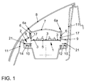
- the basic structure of a lighting device is described with reference to Fig. 1 explained.
- the lighting device of this example provides a tail / brake light and a turn signal as a direction indicator.
- the lighting device comprises a first lighting module 1 and a second lighting module 2.
- the light module 1 comprises a plurality of light emitting diodes 3, a circuit board 5, on which the light emitting diodes 3 are mounted, and reflector surfaces 18, which reflect the light emitted by the light emitting diodes 3 in the emission direction of the illumination device.
- a circuit board 5 on which the light emitting diodes 3 are mounted, and reflector surfaces 18, which reflect the light emitted by the light emitting diodes 3 in the emission direction of the illumination device.
- strip conductors are provided, which supply the terminals of the light emitting diodes 3 with electricity and drive them.
- the ballast for the LEDs is provided on this board 5.
- a total of 16 red LEDs are mounted on the board 5.
- the board 5 is circular. It is a standard board that can be used on several vehicles with a uniform basic design.
- the attachment of the first lighting module 1 in the lighting device via a plug-in, clip and / or latching connection to a receptacle 6.
- the board 5 is connected at its edge to a housing element 17.
- the attachment of the first light-emitting module 1 takes place on the receptacle 6. It is locked to the receptacle 6.
- the connection between the light module 1 and the receptacle 6 should be a simple removal and insertion of the light module 1, such. B. in conventional light bulbs allow.
- the receptacle 6 is in the example shown a part of the intermediate lens 7. The light module 1 is thus locked to the intermediate lens 7.
- the electrical connection of the board 5 can be done either via the plug, clip and / or locking connection between the light module 1 and the receptacle 6 or separately.
- the connection between the housing 17 of the light module 1 and the receptacle 6 is only the mechanical attachment of the light module 1 and the electrical connection of the board via separate leads.
- the second lighting module 2 is configured for a direction indicator designed as an orange flashing light.
- As light sources serve several light emitting diodes 14. They are mounted on a circuit board 10. On the board 10 are a total of 24 LEDs in the Color yellow or red color attached.
- the circuit board 10 can be attached either by means of a plug-in, clip and / or latching connection to a receptacle, such as the housing 11 of the lighting device. On the other hand, the board 10 may also be screwed to the housing 11.
- an intermediate lens 9 is arranged, which is designed in clear glass optics.
- the intermediate plate 9 is provided between a housing 11 of the lighting device or the reflector 19 on the one hand and the receptacle 6 for the first lighting module 1 on the other hand. It forms a circular ring which surrounds the first lighting module 1. It goes directly into the receptacle 6 and finally into the intermediate disk 7 for the first lighting module 1.
- the washer 9, the receptacle 6 and the washer 7 may thus be integrally formed.
- a metal layer 6a e.g. by vapor deposition, be applied.
- chromium can be vapor-deposited. This metal layer delimits the intermediate disk 9 optically from the intermediate disk 7.
- a further intermediate disk 21 can optionally also be provided, with which the light output of the light emitted by the light-emitting diodes 14 can be influenced.
- the annular plate 10 is located behind the board 5 with respect to the radiation direction, in the radial direction, the board 10 is laterally of the board 5, i. it surrounds the light module 1.
- FIGS. 2 and 3 show an embodiment in which the inner light module 1 as a turn signal provides a flashing light and the second light module 2 surrounding this light module 1 provides a brake and tail light.
- the eight LEDs 14 of the light module 2 are red, the LED 3 of the light module 1 is yellow. They are mounted on separately provided boards 5 and 10. However, these are in one plane.
- the diameter of the lighting device in this case is compatible with conventional lighting devices for vehicles, so that the lighting device can be installed, for example, in a tail light of a vehicle without changing the shots.
- the boards 5 and 10 are standard boards, which can be used in several vehicles if the basic design of these vehicles has been standardized.
- the boards 5 and 10 are interchangeable by a plug and / or locking connection as conventional light bulbs.
- Fig. 4 shows an embodiment of the invention, in which the first inner light module 1 provides the brake and tail light and the outer ring of the light module 2 as a direction indicator a flashing light.
- all light sources are LEDs.
- the driving of the light-emitting diodes takes place in such a way that the light intensity of the taillight is 5% and the brake light is 60% or, if a rear fog lamp is switched on, 90%.
- a further embodiment of the invention is shown, in which the lighting module 2 is divided and provides different lighting functions. On the one hand it can provide a tail and brake light in the area 12 and on the other hand in the area 13 a rear fog lamp.
- the LEDs 15 are provided and for the rear fog lights, the LEDs 16. All LEDs are executed in red, but they are controlled separately depending on their light function.
- the middle three light-emitting diodes 3 of in Fig. 5 Training shown are yellow LEDs for the flashing light of the direction indicator.
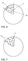
- a lighting module having LEDs Based on 6 and 7 is a further embodiment of a lighting module having LEDs, explained. It shows the Fig. 6 a view of a known light module and the Fig. 7 the inventive design of the light module.
- This embodiment according to the invention can be used in conjunction with the previously explained embodiments, in particular in the lighting module 1.
- Each light-emitting diode 3 are associated with reflectors 18. These reflectors 18 are substantially circular in plan view. So that the surface of the light module is filled as well as possible, the reflectors 18 are partially cut out. In known lighting modules of this type results in the edge region of the light module, a lighting surface dead surface 22. In the inventive design of the light module this photometric dead surface 22 is avoided.
- the reflectors 18 fill the light module 1 completely. For this purpose, the reflectors 18 are cut out accordingly in the edge region of the example disk-shaped light module 1.
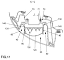
- the 8 to 12 show another example of a lighting device in an outside view and various sectional views.
- the lighting device is closed to the outside by a lens 50, which is preferably carried out in clear glass optics.
- the lens 50 adjoins body parts 60.
- the receptacle 70 (see. Fig. 11 ) is provided for the attachment of the first lighting module 30.
- the receptacle 80 (see. Fig. 9 ) intended.
- the lighting modules 30 and 40 are fastened by means of the screws 71 and 81 to these receptacles 70 and 80.
- the first lighting module 30 has a lateral cylindrical wall 90. Within this boundary 90 are honeycomb reflector surfaces 100, in whose honeycomb each light emitting diodes 31 are arranged.
- the reflector surfaces 100 consist of a base, for example made of plastic, which is provided with a reflective layer, for. B. of aluminum or chromium, vaporized.
- the LEDs 31 are mounted on a first board 110 which is disposed within the cylindrical wall 90 behind the reflector surfaces 100. In the attachment points for the LEDs 31, the reflector surfaces 100 each have openings. In the emission direction of the LEDs 31, an intermediate lens 120 is provided on the cylindrical wall 90.
- the second lighting module 40 concentrically surrounds the first lighting module 30.
- it is optically set behind the first lighting module 30. It comprises an inner reflector surface 130, which essentially continues the cylindrical wall 90 of the first light-emitting module 30 in the emission direction of the illumination device to the rear (opposite to the emission direction). At the end of this reflector wall 130 bends radially outward, to the point at which the light-emitting diode 41 of the second light-emitting module 40 is attached.
- On the radially outer side of the second light module 40 has a reflector surface 140, which extends substantially as far as the cylindrical wall 90 to the front.
- the reflector surfaces 130 and 140 of the second light module 40 also form honeycomb-shaped depressions for the LEDs 41. They are also mounted on an annular second board 150. In this case, the LEDs 41 are arranged in the emission direction behind the LEDs 31. Furthermore, the light-emitting diodes 41 surround the light-emitting diodes 31 concentrically.
- the two lighting modules 30 and 40 are inserted into one another. They can be exchanged separately. To remove the first light module 30, only the screws 71 need to be loosened. The light module 30 can then be pulled out. To replace the light module 40, only the screws 81 need to be loosened.
- the light-emitting diodes 41 of the second light-emitting module 41 can be designed as duo light-emitting diodes.
- duo light-emitting diodes two LEDs are integrated, which can shine with two different colors. For example, such a duo light emitting diode in red and / or orange light.
- the duo LEDs are controlled so that they flash and emit orange light.
- light-emitting diodes for the tail / brake light and for the flashing light those of the Power-TopLED type from Osram Optosemiconductors can be used.
- the number of LEDs used in the embodiments is exemplary. It can vary depending on the light function and light intensity of the LEDs used.
- light-emitting diodes of the Super-flux LED type from LumiLED can be used.
- the number of LEDs used in the embodiments is exemplary. It can vary depending on the light function and light intensity of the LEDs used. All light-emitting diodes are provided with current limiting circuitry with series resistors and a diode to protect against reverse polarity and negative voltage spikes. A dimming of the LEDs for a change from the brake light to tail light is realized by clocking from the rear control unit.
- the lighting devices described above can be used to provide further divisions of lighting functions.
- the first light module can provide a reversing light and the second light module a fog light.
- the first light module may be a reversing light and the second light module may be a tail / brake light.
- the first light module can provide both a reversing light and a rear fog lamp and the second light module provide the tail / brake light.
Landscapes
- Engineering & Computer Science (AREA)
- Mechanical Engineering (AREA)
- Physics & Mathematics (AREA)
- Microelectronics & Electronic Packaging (AREA)
- Optics & Photonics (AREA)
- General Engineering & Computer Science (AREA)
- Non-Portable Lighting Devices Or Systems Thereof (AREA)
- Lighting Device Outwards From Vehicle And Optical Signal (AREA)
Claims (6)
- Dispositif d'éclairage pour véhicules comprenant un premier module lumineux (1) et un deuxième module lumineux (2), lesquels comprennent des diodes électroluminescentes (3, 14), le deuxième module lumineux (2) entourant le premier module lumineux (1) et les diodes électroluminescentes (3, 14) des deux modules lumineux (1, 2) étant fixées sur des platines (5, 10) conçues séparément l'une de l'autre qui se trouvent dans un plan,
caractérisé en ce- que le premier module lumineux (1) et le deuxième module lumineux (2) comprennent respectivement une pluralité de diodes électroluminescentes (3, 14),- que pour fournir une fonction de feu arrière, les diodes électroluminescentes à la fois du premier et du deuxième module lumineux peuvent être commandées de telle sorte qu'elles éclairent avec une intensité lumineuse dans une plage de 5 % à 20 % de l'intensité lumineuse maximale des diodes électroluminescentes, et- que pour fournir une fonction de feu stop, les diodes électroluminescentes du premier module lumineux peuvent être commandées de telle sorte qu'elles éclairent avec une intensité lumineuse dans une plage de 60 % à 100 % inclus de l'intensité lumineuse maximale des diodes électroluminescentes. - Dispositif d'éclairage selon la revendication 1, caractérisé en ce que le deuxième module lumineux (2) est formé par un anneau qui entoure le premier module lumineux (1).
- Dispositif d'éclairage selon l'une des revendications précédentes, caractérisé en ce qu'un réflecteur est associé à chaque diode électroluminescente (3, 14) et en ce que les réflecteurs du module lumineux (1, 2) remplissent celui-ci de telle sorte qu'il ne se produit aucune surface morte (22) du point de vue de la technique d'éclairage.
- Dispositif d'éclairage selon l'une des revendications précédentes, caractérisé en ce que le deuxième module lumineux (2) fournit un feu clignotant en tant qu'indicateur de changement de direction, les diodes électroluminescentes (14) du premier et du deuxième module lumineux (1, 2) pouvant être commandés de telle sorte que l'intensité lumineuse du feu arrière est égale à 5 % et celle du feu stop à 60 % ou, lorsqu'un feu antibrouillard arrière est allumé, à 90 % de l'intensité lumineuse maximale des diodes électroluminescentes.
- Dispositif d'éclairage selon l'une des revendications précédentes, caractérisé en ce que le deuxième module lumineux (2) est divisé et fournit différentes fonctions lumineuses.
- Dispositif d'éclairage selon la revendication 5, caractérisé en ce que le deuxième module lumineux (2) fournit dans une zone (12) un feu arrière et un feu stop et, dans une autre zone (13), un feu antibrouillard arrière.
Applications Claiming Priority (3)
| Application Number | Priority Date | Filing Date | Title |
|---|---|---|---|
| DE10324393 | 2003-05-28 | ||
| DE10332127 | 2003-07-15 | ||
| EP04721145A EP1633597B1 (fr) | 2003-05-28 | 2004-03-17 | Dispositif d'eclairage pour vehicules, comportant un module luminescent pourvu de diodes electroluminescentes |
Related Parent Applications (1)
| Application Number | Title | Priority Date | Filing Date |
|---|---|---|---|
| EP04721145A Division EP1633597B1 (fr) | 2003-05-28 | 2004-03-17 | Dispositif d'eclairage pour vehicules, comportant un module luminescent pourvu de diodes electroluminescentes |
Publications (2)
| Publication Number | Publication Date |
|---|---|
| EP1955895A1 EP1955895A1 (fr) | 2008-08-13 |
| EP1955895B1 true EP1955895B1 (fr) | 2016-05-25 |
Family
ID=33491647
Family Applications (2)
| Application Number | Title | Priority Date | Filing Date |
|---|---|---|---|
| EP04721145A Expired - Lifetime EP1633597B1 (fr) | 2003-05-28 | 2004-03-17 | Dispositif d'eclairage pour vehicules, comportant un module luminescent pourvu de diodes electroluminescentes |
| EP08157295.0A Expired - Lifetime EP1955895B1 (fr) | 2003-05-28 | 2004-03-17 | Dispositif d'éclairage avec un module DEL |
Family Applications Before (1)
| Application Number | Title | Priority Date | Filing Date |
|---|---|---|---|
| EP04721145A Expired - Lifetime EP1633597B1 (fr) | 2003-05-28 | 2004-03-17 | Dispositif d'eclairage pour vehicules, comportant un module luminescent pourvu de diodes electroluminescentes |
Country Status (5)
| Country | Link |
|---|---|
| EP (2) | EP1633597B1 (fr) |
| AT (1) | ATE399681T1 (fr) |
| DE (2) | DE502004007498D1 (fr) |
| ES (1) | ES2308164T3 (fr) |
| WO (1) | WO2004106113A1 (fr) |
Families Citing this family (11)
| Publication number | Priority date | Publication date | Assignee | Title |
|---|---|---|---|---|
| DE102005042611A1 (de) * | 2005-09-07 | 2007-03-22 | Volkswagen Ag | Beleuchtungsvorrichtung für ein Fahrzeug mit zwei Gruppen von Lichtquellen für zumindest zwei Lichtfunktionen |
| DE102006035503A1 (de) * | 2006-07-31 | 2008-02-07 | Dr.Ing.H.C. F. Porsche Ag | Heckleuchte für ein Fahrzeug |
| DE102007012256A1 (de) * | 2007-03-12 | 2008-09-18 | Schefenacker Vision Systems Germany Gmbh | Leuchte für Fahrzeuge, insbesondere für Kraftfahrzeuge |
| JP2009093807A (ja) | 2007-10-03 | 2009-04-30 | Yamaha Motor Co Ltd | 車両用灯具及びそれを備えた車両 |
| KR101262546B1 (ko) * | 2011-11-09 | 2013-05-08 | 기아자동차주식회사 | 차량용 램프구조 |
| JP6109614B2 (ja) * | 2013-03-22 | 2017-04-05 | 本田技研工業株式会社 | 鞍乗型車両の灯火器 |
| DE102014210213A1 (de) | 2013-06-20 | 2014-12-24 | Volkswagen Aktiengesellschaft | Verfahren und Vorrichtung zum Steuern einer Lichtemission einer Heckleuchte eines Fahrzeugs |
| DE102014221815A1 (de) * | 2013-10-29 | 2015-05-13 | Volkswagen Aktiengesellschaft | Leuchtvorrichtung und Scheinwerfer für ein Kraftfahrzeug |
| IT201900003119A1 (it) * | 2019-03-04 | 2020-09-04 | Italdesign Giugiaro Spa | Gruppo ottico posteriore di un veicolo e procedimento per il controllo dell'accensione di detto gruppo ottico posteriore |
| US11428380B2 (en) * | 2020-05-28 | 2022-08-30 | Charles I. Sassoon | Combination LED lamps |
| WO2025059329A1 (fr) * | 2023-09-13 | 2025-03-20 | Valeo Vision | Lumière reconfigurable fournissant de multiples configurations de lumière différentes à partir d'un logement unique et réglage de la lumière reconfigurable |
Family Cites Families (26)
| Publication number | Priority date | Publication date | Assignee | Title |
|---|---|---|---|---|
| US3425056A (en) * | 1964-11-27 | 1969-01-28 | Dietz Co R E | Warning lens having concentric lenticular elements |
| DE3315785A1 (de) * | 1983-04-30 | 1984-11-08 | Robert Bosch Gmbh, 7000 Stuttgart | Kraftfahrzeugleuchte |
| DE3916875A1 (de) | 1989-05-24 | 1990-12-06 | Ullmann Ulo Werk | Signalleuchte, insbesondere mehrkammersignalleuchte fuer kraftfahrzeuge |
| DE3930214A1 (de) | 1989-09-09 | 1991-03-28 | Ullmann Ulo Werk | Signalleuchtenpaar |
| DE4228895C2 (de) * | 1992-08-29 | 2002-09-19 | Bosch Gmbh Robert | Kraftfahrzeug-Beleuchtungseinrichtung mit mehreren Halbleiterlichtquellen |
| FR2697485B1 (fr) * | 1992-11-02 | 1995-01-20 | Valeo Vision | Feu de signalisation à éléments lumineux modulaires, pour véhicule automobile. |
| JP3181145B2 (ja) * | 1993-06-07 | 2001-07-03 | スタンレー電気株式会社 | Led光源の灯具 |
| US5838247A (en) * | 1997-04-01 | 1998-11-17 | Bladowski; Witold S. | Solid state light system |
| JP3193889B2 (ja) | 1997-06-18 | 2001-07-30 | 株式会社小糸製作所 | 車輌用灯具 |
| US6152590A (en) | 1998-02-13 | 2000-11-28 | Donnelly Hohe Gmbh & Co. Kg | Lighting device for motor vehicles |
| DE19815963A1 (de) * | 1998-04-09 | 1999-10-14 | Reitter & Schefenacker Gmbh | Leuchte, insbesondere Heckleuchte für Kraftfahrzeuge |
| DE19837553A1 (de) * | 1998-08-19 | 2000-02-24 | Hella Kg Hueck & Co | Fahrzeugleuchte |
| DE19933714B4 (de) | 1999-07-19 | 2008-07-10 | Volkswagen Ag | Leuchte mit zweiter Lichtquelle |
| JP4182600B2 (ja) | 1999-08-23 | 2008-11-19 | 市光工業株式会社 | Led光源を用いた車両用灯具 |
| DE19945775B4 (de) * | 1999-09-24 | 2005-05-25 | Audi Ag | Leuchtenanordnung als Heckleuchte für ein Kraftfahrzeug |
| EP1118813B1 (fr) * | 2000-01-21 | 2008-10-08 | Stanley Electric Co., Ltd. | Feu de signalisation pour véhicule automobile |
| JP2001229710A (ja) * | 2000-02-18 | 2001-08-24 | Stanley Electric Co Ltd | 重連型車両用灯具 |
| DE10019557A1 (de) * | 2000-04-20 | 2001-10-25 | Hella Kg Hueck & Co | Fahrzeugleuchte |
| US6527411B1 (en) * | 2000-08-01 | 2003-03-04 | Visteon Corporation | Collimating lamp |
| DE10043660A1 (de) * | 2000-09-05 | 2002-03-14 | Volkswagen Ag | Kfz-Leuchte mit LEDs |
| JP3839236B2 (ja) | 2000-09-18 | 2006-11-01 | 株式会社小糸製作所 | 車両用灯具 |
| DE10052655B4 (de) | 2000-10-24 | 2010-04-08 | Volkswagen Ag | Beleuchtungseinrichtung für Kraftfahrzeuge |
| WO2002041276A2 (fr) * | 2000-11-15 | 2002-05-23 | Snowy Village, Inc. | Avertisseur lumineux a base de diodes electroluminescentes et systeme de communication |
| DE20019923U1 (de) | 2000-11-23 | 2002-01-10 | Siemens AG, 80333 München | Aufbausystem zur Aufnahme von LED-Modulen sowie LED-Modul zur Aufnahme in einem Aufbausystem |
| DE10060489A1 (de) * | 2000-12-08 | 2002-06-13 | Hella Kg Hueck & Co | Leuchte für Fahrzeuge |
| DE10160052A1 (de) * | 2001-12-06 | 2003-06-18 | Hella Kg Hueck & Co | Fahrzeugleuchte |
-
2004
- 2004-03-17 ES ES04721145T patent/ES2308164T3/es not_active Expired - Lifetime
- 2004-03-17 WO PCT/EP2004/002778 patent/WO2004106113A1/fr not_active Ceased
- 2004-03-17 DE DE502004007498T patent/DE502004007498D1/de not_active Expired - Lifetime
- 2004-03-17 EP EP04721145A patent/EP1633597B1/fr not_active Expired - Lifetime
- 2004-03-17 AT AT04721145T patent/ATE399681T1/de active
- 2004-03-17 DE DE102004013082.5A patent/DE102004013082B4/de not_active Expired - Fee Related
- 2004-03-17 EP EP08157295.0A patent/EP1955895B1/fr not_active Expired - Lifetime
Also Published As
| Publication number | Publication date |
|---|---|
| EP1955895A1 (fr) | 2008-08-13 |
| EP1633597B1 (fr) | 2008-07-02 |
| DE102004013082A1 (de) | 2005-01-05 |
| DE102004013082B4 (de) | 2019-08-01 |
| ATE399681T1 (de) | 2008-07-15 |
| WO2004106113A1 (fr) | 2004-12-09 |
| EP1633597A1 (fr) | 2006-03-15 |
| DE502004007498D1 (de) | 2008-08-14 |
| ES2308164T3 (es) | 2008-12-01 |
Similar Documents
| Publication | Publication Date | Title |
|---|---|---|
| EP2161494B2 (fr) | Dispositif d'éclairage pour un véhicule automobile | |
| DE10011843B4 (de) | Kraftfahrzeugleuchte und Verfahren zum Einstellen verschiedener Signalisierungen | |
| DE10303430A1 (de) | Ein Frontbeleuchtungssystem für ein Kraftfahrzeug | |
| DE10105622A1 (de) | Beleuchtungseinrichtung | |
| EP1955895B1 (fr) | Dispositif d'éclairage avec un module DEL | |
| EP1431158B1 (fr) | Phare et feu de signalisation pour véhicule ferroviaire. | |
| DE102010012137A1 (de) | Kraftfahrzeug-Beleuchtungseinrichtung | |
| DE102004011600A1 (de) | Rückstrahler für Heckleuchten von Fahrzeugen, vorzugsweise von Kraftfahrzeugen | |
| EP3466756B1 (fr) | Conduit de lumière en cascade pouvant être animé | |
| EP0570987A1 (fr) | Feux arrière pour bicyclette | |
| DE102008055694A1 (de) | Stellrad | |
| DE102015002341A1 (de) | Scheinwerfer für ein Kraftfahrzeug | |
| DE102016204370B4 (de) | Infrarot-Leuchte für ein Fahrzeug | |
| DE10115806A1 (de) | Außenleuchtvorrichtung für die Außenbeleuchtung eines Fahrzeugs | |
| WO2007028451A1 (fr) | Dispositif d'eclairage destine a un vehicule comportant deux groupes de sources d'eclairage conçus pour au moins deux fonctions d'eclairage | |
| EP1338469B1 (fr) | Dispositif et procédé de contrôle d'au moins un feu de véhicule | |
| DE102008004483B4 (de) | Fahrzeugleuchte mit flexibler Leuchtmittelbaugruppe | |
| DE29902789U1 (de) | Blitzleuchteneinheit und damit aufgebaute Blitzleuchtenanordnung | |
| DE10248359A1 (de) | Hinterleuchtete Funktionsanordnung | |
| DE19533799C2 (de) | Signalleuchte für Fahrzeuge | |
| DE102008011818A1 (de) | Soffittenlampe und Verfahren zum Herstellen einer Soffittenlampe | |
| DE202017105794U1 (de) | Infrarot-Leuchte für ein Fahrzeug | |
| DE29917634U1 (de) | Taschenlampe | |
| DE102005033684A1 (de) | Beleuchtungsvorrichtung für ein Fahrzeug | |
| DE202018101959U1 (de) | LED-Rundumleuchte zum Ausstrahlen eines umlaufenden Lichtes |
Legal Events
| Date | Code | Title | Description |
|---|---|---|---|
| PUAI | Public reference made under article 153(3) epc to a published international application that has entered the european phase |
Free format text: ORIGINAL CODE: 0009012 |
|
| AC | Divisional application: reference to earlier application |
Ref document number: 1633597 Country of ref document: EP Kind code of ref document: P |
|
| AK | Designated contracting states |
Kind code of ref document: A1 Designated state(s): AT BE BG CH CY CZ DE DK EE ES FI FR GB GR HU IE IT LI LU MC NL PL PT RO SE SI SK TR |
|
| AX | Request for extension of the european patent |
Extension state: AL LT LV MK |
|
| 17P | Request for examination filed |
Effective date: 20090213 |
|
| 17Q | First examination report despatched |
Effective date: 20090311 |
|
| AKX | Designation fees paid |
Designated state(s): AT BE BG CH CY CZ DE DK EE ES FI FR GB GR HU IE IT LI LU MC NL PL PT RO SE SI SK TR |
|
| RAP1 | Party data changed (applicant data changed or rights of an application transferred) |
Owner name: VOLKSWAGEN AKTIENGESELLSCHAFT |
|
| GRAP | Despatch of communication of intention to grant a patent |
Free format text: ORIGINAL CODE: EPIDOSNIGR1 |
|
| INTG | Intention to grant announced |
Effective date: 20151203 |
|
| GRAS | Grant fee paid |
Free format text: ORIGINAL CODE: EPIDOSNIGR3 |
|
| GRAA | (expected) grant |
Free format text: ORIGINAL CODE: 0009210 |
|
| AC | Divisional application: reference to earlier application |
Ref document number: 1633597 Country of ref document: EP Kind code of ref document: P |
|
| AK | Designated contracting states |
Kind code of ref document: B1 Designated state(s): AT BE BG CH CY CZ DE DK EE ES FI FR GB GR HU IE IT LI LU MC NL PL PT RO SE SI SK TR |
|
| REG | Reference to a national code |
Ref country code: GB Ref legal event code: FG4D Free format text: NOT ENGLISH |
|
| REG | Reference to a national code |
Ref country code: CH Ref legal event code: EP |
|
| REG | Reference to a national code |
Ref country code: IE Ref legal event code: FG4D Free format text: LANGUAGE OF EP DOCUMENT: GERMAN Ref country code: AT Ref legal event code: REF Ref document number: 802000 Country of ref document: AT Kind code of ref document: T Effective date: 20160615 |
|
| REG | Reference to a national code |
Ref country code: DE Ref legal event code: R096 Ref document number: 502004015208 Country of ref document: DE |
|
| REG | Reference to a national code |
Ref country code: NL Ref legal event code: MP Effective date: 20160525 |
|
| PG25 | Lapsed in a contracting state [announced via postgrant information from national office to epo] |
Ref country code: NL Free format text: LAPSE BECAUSE OF FAILURE TO SUBMIT A TRANSLATION OF THE DESCRIPTION OR TO PAY THE FEE WITHIN THE PRESCRIBED TIME-LIMIT Effective date: 20160525 Ref country code: FI Free format text: LAPSE BECAUSE OF FAILURE TO SUBMIT A TRANSLATION OF THE DESCRIPTION OR TO PAY THE FEE WITHIN THE PRESCRIBED TIME-LIMIT Effective date: 20160525 |
|
| PG25 | Lapsed in a contracting state [announced via postgrant information from national office to epo] |
Ref country code: PT Free format text: LAPSE BECAUSE OF FAILURE TO SUBMIT A TRANSLATION OF THE DESCRIPTION OR TO PAY THE FEE WITHIN THE PRESCRIBED TIME-LIMIT Effective date: 20160926 Ref country code: SE Free format text: LAPSE BECAUSE OF FAILURE TO SUBMIT A TRANSLATION OF THE DESCRIPTION OR TO PAY THE FEE WITHIN THE PRESCRIBED TIME-LIMIT Effective date: 20160525 Ref country code: GR Free format text: LAPSE BECAUSE OF FAILURE TO SUBMIT A TRANSLATION OF THE DESCRIPTION OR TO PAY THE FEE WITHIN THE PRESCRIBED TIME-LIMIT Effective date: 20160826 Ref country code: ES Free format text: LAPSE BECAUSE OF FAILURE TO SUBMIT A TRANSLATION OF THE DESCRIPTION OR TO PAY THE FEE WITHIN THE PRESCRIBED TIME-LIMIT Effective date: 20160525 |
|
| PG25 | Lapsed in a contracting state [announced via postgrant information from national office to epo] |
Ref country code: IT Free format text: LAPSE BECAUSE OF FAILURE TO SUBMIT A TRANSLATION OF THE DESCRIPTION OR TO PAY THE FEE WITHIN THE PRESCRIBED TIME-LIMIT Effective date: 20160525 |
|
| PG25 | Lapsed in a contracting state [announced via postgrant information from national office to epo] |
Ref country code: RO Free format text: LAPSE BECAUSE OF FAILURE TO SUBMIT A TRANSLATION OF THE DESCRIPTION OR TO PAY THE FEE WITHIN THE PRESCRIBED TIME-LIMIT Effective date: 20160525 Ref country code: EE Free format text: LAPSE BECAUSE OF FAILURE TO SUBMIT A TRANSLATION OF THE DESCRIPTION OR TO PAY THE FEE WITHIN THE PRESCRIBED TIME-LIMIT Effective date: 20160525 Ref country code: SK Free format text: LAPSE BECAUSE OF FAILURE TO SUBMIT A TRANSLATION OF THE DESCRIPTION OR TO PAY THE FEE WITHIN THE PRESCRIBED TIME-LIMIT Effective date: 20160525 Ref country code: CZ Free format text: LAPSE BECAUSE OF FAILURE TO SUBMIT A TRANSLATION OF THE DESCRIPTION OR TO PAY THE FEE WITHIN THE PRESCRIBED TIME-LIMIT Effective date: 20160525 Ref country code: DK Free format text: LAPSE BECAUSE OF FAILURE TO SUBMIT A TRANSLATION OF THE DESCRIPTION OR TO PAY THE FEE WITHIN THE PRESCRIBED TIME-LIMIT Effective date: 20160525 |
|
| PG25 | Lapsed in a contracting state [announced via postgrant information from national office to epo] |
Ref country code: PL Free format text: LAPSE BECAUSE OF FAILURE TO SUBMIT A TRANSLATION OF THE DESCRIPTION OR TO PAY THE FEE WITHIN THE PRESCRIBED TIME-LIMIT Effective date: 20160525 |
|
| REG | Reference to a national code |
Ref country code: DE Ref legal event code: R097 Ref document number: 502004015208 Country of ref document: DE |
|
| REG | Reference to a national code |
Ref country code: FR Ref legal event code: PLFP Year of fee payment: 14 |
|
| PLBE | No opposition filed within time limit |
Free format text: ORIGINAL CODE: 0009261 |
|
| STAA | Information on the status of an ep patent application or granted ep patent |
Free format text: STATUS: NO OPPOSITION FILED WITHIN TIME LIMIT |
|
| 26N | No opposition filed |
Effective date: 20170228 |
|
| PG25 | Lapsed in a contracting state [announced via postgrant information from national office to epo] |
Ref country code: SI Free format text: LAPSE BECAUSE OF FAILURE TO SUBMIT A TRANSLATION OF THE DESCRIPTION OR TO PAY THE FEE WITHIN THE PRESCRIBED TIME-LIMIT Effective date: 20160525 |
|
| REG | Reference to a national code |
Ref country code: CH Ref legal event code: PL |
|
| GBPC | Gb: european patent ceased through non-payment of renewal fee |
Effective date: 20170317 |
|
| PG25 | Lapsed in a contracting state [announced via postgrant information from national office to epo] |
Ref country code: MC Free format text: LAPSE BECAUSE OF FAILURE TO SUBMIT A TRANSLATION OF THE DESCRIPTION OR TO PAY THE FEE WITHIN THE PRESCRIBED TIME-LIMIT Effective date: 20160525 |
|
| REG | Reference to a national code |
Ref country code: IE Ref legal event code: MM4A |
|
| PG25 | Lapsed in a contracting state [announced via postgrant information from national office to epo] |
Ref country code: LU Free format text: LAPSE BECAUSE OF NON-PAYMENT OF DUE FEES Effective date: 20170317 |
|
| PG25 | Lapsed in a contracting state [announced via postgrant information from national office to epo] |
Ref country code: CH Free format text: LAPSE BECAUSE OF NON-PAYMENT OF DUE FEES Effective date: 20170331 Ref country code: IE Free format text: LAPSE BECAUSE OF NON-PAYMENT OF DUE FEES Effective date: 20170317 Ref country code: LI Free format text: LAPSE BECAUSE OF NON-PAYMENT OF DUE FEES Effective date: 20170331 Ref country code: GB Free format text: LAPSE BECAUSE OF NON-PAYMENT OF DUE FEES Effective date: 20170317 |
|
| REG | Reference to a national code |
Ref country code: BE Ref legal event code: MM Effective date: 20170331 |
|
| REG | Reference to a national code |
Ref country code: FR Ref legal event code: PLFP Year of fee payment: 15 |
|
| REG | Reference to a national code |
Ref country code: AT Ref legal event code: MM01 Ref document number: 802000 Country of ref document: AT Kind code of ref document: T Effective date: 20170317 |
|
| PG25 | Lapsed in a contracting state [announced via postgrant information from national office to epo] |
Ref country code: BE Free format text: LAPSE BECAUSE OF NON-PAYMENT OF DUE FEES Effective date: 20170331 |
|
| PG25 | Lapsed in a contracting state [announced via postgrant information from national office to epo] |
Ref country code: AT Free format text: LAPSE BECAUSE OF NON-PAYMENT OF DUE FEES Effective date: 20170317 |
|
| PG25 | Lapsed in a contracting state [announced via postgrant information from national office to epo] |
Ref country code: HU Free format text: LAPSE BECAUSE OF FAILURE TO SUBMIT A TRANSLATION OF THE DESCRIPTION OR TO PAY THE FEE WITHIN THE PRESCRIBED TIME-LIMIT; INVALID AB INITIO Effective date: 20040317 |
|
| PG25 | Lapsed in a contracting state [announced via postgrant information from national office to epo] |
Ref country code: BG Free format text: LAPSE BECAUSE OF FAILURE TO SUBMIT A TRANSLATION OF THE DESCRIPTION OR TO PAY THE FEE WITHIN THE PRESCRIBED TIME-LIMIT Effective date: 20160525 |
|
| PG25 | Lapsed in a contracting state [announced via postgrant information from national office to epo] |
Ref country code: CY Free format text: LAPSE BECAUSE OF NON-PAYMENT OF DUE FEES Effective date: 20160525 |
|
| PG25 | Lapsed in a contracting state [announced via postgrant information from national office to epo] |
Ref country code: TR Free format text: LAPSE BECAUSE OF FAILURE TO SUBMIT A TRANSLATION OF THE DESCRIPTION OR TO PAY THE FEE WITHIN THE PRESCRIBED TIME-LIMIT Effective date: 20160525 |
|
| PGFP | Annual fee paid to national office [announced via postgrant information from national office to epo] |
Ref country code: FR Payment date: 20200326 Year of fee payment: 17 |
|
| PGFP | Annual fee paid to national office [announced via postgrant information from national office to epo] |
Ref country code: DE Payment date: 20200331 Year of fee payment: 17 |
|
| REG | Reference to a national code |
Ref country code: DE Ref legal event code: R119 Ref document number: 502004015208 Country of ref document: DE |
|
| PG25 | Lapsed in a contracting state [announced via postgrant information from national office to epo] |
Ref country code: DE Free format text: LAPSE BECAUSE OF NON-PAYMENT OF DUE FEES Effective date: 20211001 Ref country code: FR Free format text: LAPSE BECAUSE OF NON-PAYMENT OF DUE FEES Effective date: 20210331 |