EP1955901A1 - Lüftungsglied - Google Patents
Lüftungsglied Download PDFInfo
- Publication number
- EP1955901A1 EP1955901A1 EP06832679A EP06832679A EP1955901A1 EP 1955901 A1 EP1955901 A1 EP 1955901A1 EP 06832679 A EP06832679 A EP 06832679A EP 06832679 A EP06832679 A EP 06832679A EP 1955901 A1 EP1955901 A1 EP 1955901A1
- Authority
- EP
- European Patent Office
- Prior art keywords
- permeable membrane
- cover part
- axial direction
- support body
- vent member
- Prior art date
- Legal status (The legal status is an assumption and is not a legal conclusion. Google has not performed a legal analysis and makes no representation as to the accuracy of the status listed.)
- Granted
Links
Images







Classifications
-
- B—PERFORMING OPERATIONS; TRANSPORTING
- B65—CONVEYING; PACKING; STORING; HANDLING THIN OR FILAMENTARY MATERIAL
- B65D—CONTAINERS FOR STORAGE OR TRANSPORT OF ARTICLES OR MATERIALS, e.g. BAGS, BARRELS, BOTTLES, BOXES, CANS, CARTONS, CRATES, DRUMS, JARS, TANKS, HOPPERS, FORWARDING CONTAINERS; ACCESSORIES, CLOSURES, OR FITTINGS THEREFOR; PACKAGING ELEMENTS; PACKAGES
- B65D77/00—Packages formed by enclosing articles or materials in preformed containers, e.g. boxes, cartons, sacks or bags
- B65D77/22—Details
- B65D77/225—Pressure relief-valves incorporated in a container wall, e.g. valves comprising at least one elastic element
-
- F—MECHANICAL ENGINEERING; LIGHTING; HEATING; WEAPONS; BLASTING
- F21—LIGHTING
- F21V—FUNCTIONAL FEATURES OR DETAILS OF LIGHTING DEVICES OR SYSTEMS THEREOF; STRUCTURAL COMBINATIONS OF LIGHTING DEVICES WITH OTHER ARTICLES, NOT OTHERWISE PROVIDED FOR
- F21V31/00—Gas-tight or water-tight arrangements
- F21V31/03—Gas-tight or water-tight arrangements with provision for venting
-
- B—PERFORMING OPERATIONS; TRANSPORTING
- B60—VEHICLES IN GENERAL
- B60R—VEHICLES, VEHICLE FITTINGS, OR VEHICLE PARTS, NOT OTHERWISE PROVIDED FOR
- B60R16/00—Electric or fluid circuits specially adapted for vehicles and not otherwise provided for; Arrangement of elements of electric or fluid circuits specially adapted for vehicles and not otherwise provided for
- B60R16/02—Electric or fluid circuits specially adapted for vehicles and not otherwise provided for; Arrangement of elements of electric or fluid circuits specially adapted for vehicles and not otherwise provided for electric constitutive elements
-
- F—MECHANICAL ENGINEERING; LIGHTING; HEATING; WEAPONS; BLASTING
- F21—LIGHTING
- F21S—NON-PORTABLE LIGHTING DEVICES; SYSTEMS THEREOF; VEHICLE LIGHTING DEVICES SPECIALLY ADAPTED FOR VEHICLE EXTERIORS
- F21S45/00—Arrangements within vehicle lighting devices specially adapted for vehicle exteriors, for purposes other than emission or distribution of light
- F21S45/30—Ventilation or drainage of lighting devices
-
- H—ELECTRICITY
- H05—ELECTRIC TECHNIQUES NOT OTHERWISE PROVIDED FOR
- H05K—PRINTED CIRCUITS; CASINGS OR CONSTRUCTIONAL DETAILS OF ELECTRIC APPARATUS; MANUFACTURE OF ASSEMBLAGES OF ELECTRICAL COMPONENTS
- H05K5/00—Casings, cabinets or drawers for electric apparatus
- H05K5/02—Details
- H05K5/0213—Venting apertures; Constructional details thereof
-
- H—ELECTRICITY
- H05—ELECTRIC TECHNIQUES NOT OTHERWISE PROVIDED FOR
- H05K—PRINTED CIRCUITS; CASINGS OR CONSTRUCTIONAL DETAILS OF ELECTRIC APPARATUS; MANUFACTURE OF ASSEMBLAGES OF ELECTRICAL COMPONENTS
- H05K5/00—Casings, cabinets or drawers for electric apparatus
- H05K5/02—Details
- H05K5/0213—Venting apertures; Constructional details thereof
- H05K5/0216—Venting plugs comprising semi-permeable membranes
-
- H—ELECTRICITY
- H02—GENERATION; CONVERSION OR DISTRIBUTION OF ELECTRIC POWER
- H02K—DYNAMO-ELECTRIC MACHINES
- H02K2205/00—Specific aspects not provided for in the other groups of this subclass relating to casings, enclosures, supports
- H02K2205/09—Machines characterised by drain passages or by venting, breathing or pressure compensating means
-
- H—ELECTRICITY
- H02—GENERATION; CONVERSION OR DISTRIBUTION OF ELECTRIC POWER
- H02K—DYNAMO-ELECTRIC MACHINES
- H02K5/00—Casings; Enclosures; Supports
- H02K5/04—Casings or enclosures characterised by the shape, form or construction thereof
- H02K5/10—Casings or enclosures characterised by the shape, form or construction thereof with arrangements for protection from ingress, e.g. water or fingers
Definitions
- the present invention relates to a vent member attached to a housing.
- Vent members are attached to housings that accommodate therein electrical components of an automobile, such as lamps, sensors, and ECUs, in order not only to ensure ventilation between the interior and the exterior of the housings but also to prevent the entry of foreign matter into the interior of the housings. Examples of such vent members are disclosed in JP 2004-47425A , JP 10-85536A , and JP 2001-143524A .
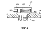
- the vent member disclosed in JP 2004-47425A includes a support body 103 on which a permeable membrane 102 is disposed and a cover part 104 attached to the support body 103 so as to cover the permeable membrane 102.
- the vent member 101 configured as above is fixed to an opening 107 of a housing 106 via an O-ring 105.
- the cover part 104 prevents damage to the permeable membrane 102 caused by an external force and deterioration to the permeability of the permeable member 102 caused by deposition of dust.
- vent members that are more excellent in durability against foreign matter.
- vent members to be used for the housings of lamps and ECUs in an automobile, there is a need for vent members not only capable of withstanding car washing, in particular, high-pressure car washing, but also capable of completely preventing the entry of water into the interior of the housings.
- the cover part 104 covers the permeable membrane 102 directly above, it stands strong against foreign matter, such as water droplets falling down from directly above.
- foreign matter such as water droplets falling down from directly above.
- it opens widely in the lateral direction, it is highly likely that foreign matter coming from the side applies a direct impact to the permeable membrane 102.
- the foreign matter adheres onto the permeable membrane 102, it remains on the permeable membrane 102 and can cause deterioration of the permeability.
- vent members disclosed in JP 10-85536A and JP 2001-143524A are configured in such a manner that the permeable membrane is covered completely with a tubular cover part. It is therefore less likely that foreign matter, such as water droplets, applies a direct impact to the permeable membrane.
- the configuration that resists the entry of foreign matter into the interior of the cover part can bring out an adverse effect in some cases. More specifically, once the foreign matter enters the interior of the cover part, the foreign matter will not be readily discharged to the exterior of the cover part or it frequently remains on the permeable membrane and on the inner surface of the cover part.
- vent members disclosed in JP 10-85536A and JP 2001-143524A fail to achieve sufficient dust-proof and water-proof effects unless they are used in a posture in which the cover part is oriented vertically upward. When used in a posture in which the cover part is oriented vertically downward, foreign matter can enter the interior of the cover part with relative ease.
- the vent members disclosed in JP 10-85536A and JP 2001-143524A have limitations of use that are absent with the vent member shown in Fig. 14 .
- the invention has an object to provide a vent member configured in such a manner that the permeable membrane is least susceptible to a direct impact of foreign matter, such as water droplets coming from all directions, and the foreign matter hardly remains in the interior regardless of loose limitations of use.
- vent member to be attached to a housing that needs ventilation.
- the vent member includes a support body having a through-hole to serve as a passage for ventilation between an interior and an exterior of the housing, a permeable membrane disposed on the support body so as to close one of the openings of the through-hole, and a cover part covering the support body from a side where the permeable membrane is disposed.
- the support body includes a mesa-like portion that is convex to the upper side in the axial direction and the through-hole opens in the mesa-like portion for the permeable membrane disposed thereon.
- the cover part includes a ceiling portion facing the permeable membrane and a side wall portion extending from a periphery of the ceiling portion to the lower side in the axial direction.
- the ceiling portion is provided with a ventilation hole that brings an interior and an exterior of the cover part into communication with each other while establishing a positional relationship in which the ventilation hole does not overlap a permeable region of the permeable membrane with respect to the axial direction.
- the side wall portion extends to the lower side in the axial direction below a position at which the permeable membrane is disposed, so that a clearance bringing the interior and the exterior of the cover part into communication with each other is secured between the side wall portion and the support body.
- the permeable membrane is protected entirely along a circumferential direction by the side wall portion.
- the ventilation hole is made in the ceiling portion of the cover part that protects the permeable membrane.
- the ventilation hole makes ventilation between the interior and the exterior of the cover part satisfactory.
- the ventilation hole has a positional relationship in which it does not overlap a permeable region of the permeable membrane in the axial direction.
- the side wall portion of the cover part protects the permeable membrane entirely along the circumferential direction by extending to the lower side in the axial direction below the position at which the permeable membrane is disposed. Accordingly, as long as a direction is perpendicular to the axial direction (in-plane direction), the permeable membrane is protected in a reliable manner from foreign matter coming from any direction.
- a clearance is secured between the side wall portion of the cover part and the support body. To be more specific, it is possible efficiently to discharge water having entered the interior of the cover part through the ventilation hole made in the ceiling portion to the exterior of the cover part through the clearance between the side wall portion of the cover part and the support body.
- vent member of the invention in any of the following cases: (i) where the vent member is used in a posture in which the ceiling portion of the cover part is oriented vertically upward; (ii) where the vent member is used in a posture in which the ceiling portion of the cover part is oriented vertically downward; and (iii) where the vent member is used in a posture in which the ceiling portion of the cover part is oriented horizontally, it is possible to achieve the action to discharge water having entered the interior of the cover part to the exterior of the cover part at the same level of efficacy. The limitations of use are therefore relaxed.
- vent member configured in such a manner that the permeable membrane is least susceptible to a direct impact of foreign matter, such as water droplets coming from all directions, and the foreign matter hardly remains in the interior regardless of relaxed limitations of use.
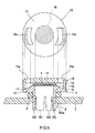
- Fig. 1 is a perspective view of a vent member according to a first embodiment of the invention.
- Fig. 2 is an exploded perspective view of the vent member shown in Fig. 1 .
- Fig. 3 is a cross section of the vent member taken on line A-A of Fig. 1 .
- Fig. 4 is a cross section of the vent member taken on line B-B of Fig. 1 .
- Fig. 13 is an overall view of a housing to which the vent member of Fig. 1 is attached. As is shown in Fig. 13 , the vent member 1 shown in Fig. 1 through Fig. 4 is attached, for example, to the opening of a housing 7 of an electrical component of an automobile, and forms a ventilation structure 100 to enable ventilation between the interior and the exterior of the housing 7.
- the vent member 1 includes a support body 2 having a through-hole 3 to serve as a passage for ventilation between the interior and the exterior of the housing 7, a permeable membrane 6 disposed on the support body 2 so as to close one of the openings of the through-hole 3, and a cover part 10 covering the support body 2 from the side where the permeable membrane 6 is disposed.
- One of the openings of the through-hole 3 made in the support body 2 is closed with the permeable membrane 6 and the other opening is exposed to the interior of the housing 7.
- the permeable membrane 6 is capable of preventing the entry of foreign matter, such as water droplets and dust, into the interior of the housing 7 while allowing permeation of a gas.
- the internal pressure of the housing 7 is maintained equal to the external pressure by the gas permeation action of the permeable membrane 6.
- the cover part 10 is provided with ventilation holes 10a that bring the interior and the exterior of the cover part 10 into communication with each other. Further, notches 10b made in a side wall portion 12 of the cover part 10 define a clearance between the cover part 10 and the support body 2. A liquid and a gas are allowed to circulate between the interior and the exterior of the cover part 10 through these ventilation holes 10a and notches 10b. Because the ventilation holes 10a are made at positions sufficiently distant from the center axis line O, foreign matter having entered through the ventilation holes 10a hardly adheres directly onto the permeable membrane 6.
- the support body 2 to which the permeable membrane 6 is fixed has a shape of a mesa, foreign matter having entered through the notches 10b of the cover part 10 hardly adheres directly onto the permeable membrane 6.
- the structure described as above makes it possible to prevent the foreign matter from adhering onto the permeable membrane 6 while ensuring satisfactory ventilation between the interior and the exterior of the cover part 10.
- the support body 2 like a mesa and providing the cover part 10 with the ventilation holes 10a and the notches 10b, the foreign matter (in particular, water) having entered the interior of the cover part 10 is discharged smoothly to the exterior of the cover part 10.
- a direction parallel to the thickness direction of the permeable membrane 6 is defined as the axial direction and a direction perpendicular to the axial direction is defined as the in-plane direction.
- the axial direction is a direction parallel to the center axis line O of the through-hole 3.
- the side oriented toward the exterior of the housing 7 is defined as the upper side and the side oriented toward the interior of the housing 7 (the side where the opening connected to the housing 7 is positioned) is defined as the lower side.
- the support body 2 is formed of a mesa-like portion 14, a base portion 15 adjacent to the mesa-like portion 14 on the lower side thereof, and leg portions 161 and 162.
- the mesa-like portion 14 is a portion in a shape that is convex to the upper side in the axial direction.
- the through-hole 3 opens in the mesa-like portion 14 for the permeable membrane 6 disposed thereon.
- the base portion 15 forms a portion that continues to the lower side of the mesa-like portion 14 and is of a ring shape (or a tubular shape) having a larger diameter than the mesa-like portion 14.
- the top face 14p (upper surface) of the mesa-like portion 14 on which the permeable membrane 6 is disposed is positioned on the upper side in the axial direction above the outer periphery of the base portion 15.
- the mesa-like portion 14 has the top face 14p that is parallel to the in-plane direction and a side face 14q that continues to the top face 14p.
- the side face 14q inclines with respect to both the axial direction and the top face 14p.
- the mesa-like portion 14 is of a shape whose outside diameter gradually is reduced in the direction of the upper side in the axial direction.
- the mesa-like portion 14, however, may be of a shape in which the side face 14q becomes parallel to the axial direction, that is, a shape whose outside diameter is reduced step-wise.
- the base portion 15 is provided with support body side engagement portions 17 used to fix the cover part 10.
- the support body side engagement portions 17 are portions used to fix the cover part 10, and provided at three points (plural points) along the circumferential direction of the base portion 15 to enclose the permeable membrane 6 at equiangular intervals (predetermined intervals).
- notches that are concave toward the center axis line O are made in the base portion 15 and used as the support body side engagement portions 17.
- the leg portions 161 and 162 are portions that continue to the base portion 15 on the side opposite to the mesa-like portion 14 and extend to the lower side in the axial direction. By inserting these leg portions 161 and 162 into the opening 8 of the housing 7, it is possible to fix the support body 2 to the housing 7. Also, the leg portions 161 and 162 are divided into six parts along the circumferential direction. Of the six leg portions 161 and 162, three leg portions 161 have fixing portions 161a.
- the fixing portions 161a are portions that are convex outward in the radial direction.
- the leg portions 161 having the fixing portions 161a and the leg portions 162 having no fixing portions 161a are arranged alternately.
- the seal ring 9 is an elastic part made of elastomers, such as NBR (nitrile rubber), EPDM (ethylene-propylene rubber), silicone rubber, fluorocarbon rubber, acrylic rubber, and nitrile hydride rubber, foams, or foams with adhesive layer.
- the fixing portions 161a exposed to the interior of the housing 7 play a role of returns and prevent the leg portions 161 and 162 from falling off from the opening 8 of the housing 7.
- the vent member 1 consequently is fixed to the housing 7.
- it may be configured in such a manner that the vent member is fixed to the housing 7 by inserting (screwing) threading leg portions into the opening 8 of the housing 7.
- the support body 2 described as above can be manufactured using typical molding methods, such as injection molding, compression molding, and cutting, by making the base portion 15, the mesa-like portion 14, and the leg portions 161 and 162 into one piece.
- thermoplastic resin such as PBT (polybutylene terephthalate), PA (nylon), and PET (polyethylene terephthalate), and thermoplastic elastomers, such as EPDM (ethylene propylene diene rubber) and silicone rubber, are available.
- Materials of the support body 2 may contain pigments, such as carbon black and titanium white, reinforcing fillers, such as glass particles and glass fibers, and water-repellent materials.
- a liquid-repellent treatment on the surface of the support body 2 makes it easier to eliminate a liquid (water or oil) having entered the interior of the cover part 10.
- Other treatments such as easy-adhesion treatment, insulating treatment, semiconductor treatment, and conducting treatment, may be applied to the support body 2.
- a structure and a material of the permeable membrane 6 are not particularly limited as long as it is a membrane that allows permeation of a gas and inhibits permeation of a liquid.
- the permeable membrane 6 formed by laminating a resin porous membrane 4 and a reinforcing layer 5 is shown as an example. By providing the reinforcing layer 5, it is possible to form the permeable membrane 6 with high strength.
- a material of the resin porous membrane 4 it is possible to use a fluorocarbon resin porous material or a polyolefin porous material, which can be manufactured by a known drawing method or extracting method.
- fluorocarbon resin examples include but not limited to polytetrafluoroethylene (PTFE), polychlorotrifluoroethylene, a copolymer of tetrafluoroethylene and hexafluoropropylene, and a copolymer of tetrafluoroethylene and ethylene.
- monomers forming polyolefin include but not limited to ethylene, propylene, and 4-methylpentene-1,1 butene. It is possible to use polyolefin obtained by polymerizing these monomers alone or copolymerizing these monomers.
- a nanofiber film porous material using polyacrylnitrile, nylon, polylactate, and so forth can be used as well. It is preferable to use, in particular, a PTFE porous material furnished with a high function of preventing the entry of foreign matter into the interior of the housing while ensuring ventilation with a small area.
- Liquid-repellent treatment may be applied to the resin porous membrane 4 depending on the use of the housing.
- the liquid-repellent treatment can be applied by coating the resin porous membrane 4 with a substance having small surface tension and letting it dry followed by curing. It is sufficient for a liquid-repellent agent used in the liquid-repellent treatment to form a coating film with surface tension lower than that of the resin porous membrane 4.
- a liquid-repeuent agent including polymers having perfluoroalkyl groups is suitable.
- the coating of the liquid-repellent agent can be performed by means of impregnation, spraying, and so forth. Also, from the viewpoint of ensuring a sufficient water-proof capability, it is preferable that an average pore diameter of the resin porous membrane 4 is in a range of 0.01 ⁇ m to 10 ⁇ m, both inclusive.
- a material of the reinforcing layer 5 is more permeable than the resin porous membrane 4.
- a fabric, a nonwoven fabric, a mesh, a net, a sponge, a foam, and a porous material made of resin or metal are available.
- a method for joining the resin porous membrane 4 and the reinforcing layer 5 can be a bonding method by means of adhesive laminate, heat laminate, heat welding, or ultrasonic welding, or with the use of an adhesive.
- the thickness of the permeable membrane 6 can be adjusted, for example, in a range of 1 ⁇ m to 5 mm. It is preferable that the permeability of the resin porous membrane 4 or the permeable membrane 6 in Gurley value is 0.1 to 300 sec/100 cm 3 .
- the permeable membrane 6 is fixed to the support body 2 by means of thermal welding.
- the permeable membrane 6 can be fixed to the support body 2 by other methods, for example, by means of ultrasonic welding or with the use of an adhesive.
- the cover part 10 is formed of a ceiling portion 11 and a side wall portion 12.
- a cover part 10 can be manufactured from the same material as the material of the support body 2 by making the ceiling portion 11 and the side wall portion 12 into one piece by a known injection molding method.
- the ceiling portion 11 is almost of a disc shape and provided with the ventilation holes 10a and 10a at two points in the outer peripheral portion.
- the number of the ventilation holes 10a is not particularly limited, and it is preferable to provide them at two to four points (plural points) along the circumferential direction at predetermined intervals.
- a part of the inner peripheral surface of the ventilation hole 10a forms an inclined surface that is inclined with respect to the axial direction and the in-plane direction in order to improve the water discharging capability.
- the side wall portion 12 is of a tubular shape that extends to the lower side almost straight from the outer periphery of the ceiling portion 11.
- the side wall portion 12 of the cover part 10 includes cover side engagement portions 121 that engage with the support body side engagement portions 17 of the support body 2.
- the notches 10b and 10b are formed adjacently to the cover side engagement portions 121 on either side.
- the notches 10b made in the side wall portion 12 at plural points (six points in this embodiment) along the circumferential direction define a clearance AR 1 that brings the interior and the exterior of the cover part 10 into communication with each other.
- the cover side engagement portions 121 obtain moderate flexibility owing to the notches 10b and 10b formed adjacently on either side. When configured in this manner, not only can the cover part 10 be attached to the support body 2 with ease, but also the possibility of damaging the cover side engagement portions 121 at the time of attachment can be lowered. It should be noted, however, that the cover part may be fixed directly to the support body with the use of an adhesive or by means of ultrasonic welding by omitting the engagement portions 121 and 17.
- each of the permeable membrane 6, the support body 2, and the cover part 10 is almost of a disc shape when viewed in a plane.
- the permeable membrane 6, the cover part 10, the support body 2, and the seal ring 9 are disposed concentrically about the common center axis line O.
- the support body 2 and the cover part 10 are adjusted to be of sizes in which the outlines appearing when projected in the axial direction almost coincide with each other. In short, the outside diameter of the support body 2 and the outside diameter of the cover part 10 are almost equal to each other. When configured in this manner, it is advantageous in reducing the vent member 1 in size.
- the vent member of a type disclosed in JP 2001-143524A is used in a state where it inserted into a tubular portion of the housing.
- the vent member therefore inevitably protrudes noticeably from the housing. Accordingly, a large attachment space is required.
- the vent member 1 of this embodiment because only a hole has to be made in the housing 7, it is possible to achieve an extremely compact ventilation structure. Meanwhile, all the dust-proof and water-proof capabilities, the ventilation and the water discharging capability between the interior and the exterior of the cover part, and the attachment ease of to the housing are as good as or better than those of the conventional vent members.
- a clearance AR 2 functioning as a passage for ventilation is defined between the ceiling portion 11 of the cover part 10 and the permeable membrane 6.
- the clearance AR 1 functioning as a passage for ventilation is secured between the base portion 15 of the support body 2 and the side wall portion 12 of the cover part 10 on the basis of the notches 10b made in the side wall portion 12 of the cover part 10. A gas is allowed to flow in and out between the interior and the exterior of the housing 7 through these clearances AR 1 and AR 2 .
- each ventilation hole 10a has a positional relationship in which when the inner periphery thereof is extended straight in the axial direction, it crosses the side face 14q of the mesa-like portion 14. Also, it is configured in such a manner that the permeable membrane 6 is invisible from the upper side in the axial direction through the ventilation holes 10a.
- the positional relationship as described above makes it possible to prevent foreign matter from directly adhering onto the permeable region 6k of the permeable membrane 6 even in a case where foreign matter, such as water droplets coming from the axial direction, enters the interior of the cover part 10 through the ventilation holes 10a. More preferably, the top face 14p of the mesa-like portion 14 in which the permeable membrane 6 is disposed does not overlap the ventilation holes 10a in the axial direction.
- a straight line TF linking the bottom end of the ventilation hole 10a on the inner peripheral side and the top end on the outer peripheral side does not intersect the permeable region 6k of the permeable membrane 6.
- an arbitrary straight line passing through the permeable region 6k of the permeable membrane 6 inevitably passes through the cover part 10.
- the permeable region 6k of the permeable membrane 6 means the region 6k in the permeable membrane 6 where a gas is actually allowed to permeate, that is, it is a region facing the through-hole 3 of the support body 2.
- the region 6j other than the permeable region 6k is a region supported on (fixed to) the mesa-like portion 14 of the support body 2.
- the side wall portion 12 of the cover part 10 protects the permeable membrane 6 entirely along the circumferential direction by extending to the lower side in the axial direction below the top face 14p of the mesa-like portion 14.
- the side wall portion 12 for the portion where neither the cover side engagements portions 121 nor the notches 10b and 10b are formed, the length in the axial direction is adjusted so that this portion almost comes into contact with the base portion 15 of the support body 2.
- the engagement portions 121 and 17 are omitted, a portion where no notches 10b are formed in the side wall portion 12 of the cover part 10 is joined directly to the base portion 15 of the support body 2.
- the notches 10b made in the side wall portion 12 of the cover part 10 define the clearance AR 1 to serve as a passage for ventilation between the cover part 10 and the base portion 15 of the support body 2.
- H1 be the height of the clearance AR 1 with respect to the axial direction
- H2 be the height (protruding height) of the mesa-like portion 14 of the support body 2 with respect to the axial direction
- H2 > H1 is established in this embodiment.
- the vent member 1 of this embodiment even in a case where water (indicated by arrows in the drawing) enters the interior of the cover part 10 through the ventilation holes 10a and the notches 10b, water does not impinge directly on the permeable membrane 6, and instead, it impinges on the side face 14q of the mesa-like portion 14.
- Fig. 10A in a case where the vent member 1 is used in a posture in which the cover part 10 is oriented vertically upward, water having entered the interior of the cover part 10 flows down on the side face 14q of the mesa-like portion 14 and thereby is discharged quickly to the exterior of the cover part 10 through the notches 10b.
- the mesa-like portion 14 can achieve a satisfactory water discharging capability by adjusting the angle of inclination of the side face 14q with respect to the top face 14p to a suitable angle (for example, in a range of 30° to 90°).
- the vent member 1 is used in a posture in which the cover part 10 is oriented sideways ( Fig. 10B ) or in a posture in which it is oriented vertically downward ( Fig. 10C ). Nevertheless, because the cover part 10 is provided with the ventilation holes 10a and the notches 10b, should water enter the interior of the cover part 10, it is possible to discharge the water quickly through the ventilation holes 10a and/or the notches 10b by gravity and/or inertial force induced by acceleration and deceleration of an automobile. In addition, because the ventilation holes 10a and the notches 10b are formed at plural points, the satisfactory water discharging capability as described above can be achieved without having to fine-tune the posture about the center axis line O. In short, the vent member 1 can be attached to the housing 7 by a simple operation.
- a vent member 21 shown in Fig. 11 is the same as the vent member 1 described above except that the leg portions 161 and 162 are omitted.
- the vent member 21 is used in a state where the base portion 15 of a support body 22 is joined directly to the opening 8 of the housing 7 with an adhesive.
- this configuration raises a need to join the components with an adhesive, it is possible to ensure higher air tightness because a problem, such as deterioration of a seal ring, is eliminated.
- the housing 7 and the vent member 21 may be made into one piece by a known insert molding method by disposing the vent member 21 inside a forming mold used to shape the housing 7. Because the vent member 21 as described above does not use a seal ring, it is possible to reduce an amount of protrusion from the surface of the housing 7 by a comparable amount.
- the vent member 31 shown in Fig. 12 includes a mesa-like portion 34 having a surface 34q, which is a curved surface, and a support body 32 including a base portion 35 positioned on the lower side of the mesa-like portion 34.
- the vent member 31 shown in Fig. 12 includes a mesa-like portion 34 having a surface 34q, which is a curved surface, and a support body 32 including a base portion 35 positioned on the lower side of the mesa-like portion 34.
- vent members 1, 21, and 31 are suitable for the housings of electrical components for automobile, such as head lamps, rear lamps, fog lamps, turn lamps, back lamps, motor cases, pressure sensors, pressure switches, and ECUs. It is possible to achieve significant advantages by attaching the vent members 1, 21, and 31 to the housings of electrical components for automobile, in particular, lamps and ECUs that are exposed directly to the weather and undergo streams of water during car washing. Also, besides the electrical components for automobile, the vent members 1, 21, and 31 can be adopted suitably as housings of electric products, such as mobile communication devices, cameras, electric shavers, and electric toothbrushes.
Landscapes
- Engineering & Computer Science (AREA)
- General Engineering & Computer Science (AREA)
- Mechanical Engineering (AREA)
- Microelectronics & Electronic Packaging (AREA)
- Arrangement Of Elements, Cooling, Sealing, Or The Like Of Lighting Devices (AREA)
- Non-Portable Lighting Devices Or Systems Thereof (AREA)
- Casings For Electric Apparatus (AREA)
- Surgical Instruments (AREA)
- Self-Closing Valves And Venting Or Aerating Valves (AREA)
- Hooks, Suction Cups, And Attachment By Adhesive Means (AREA)
Applications Claiming Priority (2)
| Application Number | Priority Date | Filing Date | Title |
|---|---|---|---|
| JP2005333394A JP4672530B2 (ja) | 2005-11-17 | 2005-11-17 | 通気部材 |
| PCT/JP2006/322748 WO2007058206A1 (ja) | 2005-11-17 | 2006-11-15 | 通気部材 |
Publications (3)
| Publication Number | Publication Date |
|---|---|
| EP1955901A1 true EP1955901A1 (de) | 2008-08-13 |
| EP1955901A4 EP1955901A4 (de) | 2009-04-08 |
| EP1955901B1 EP1955901B1 (de) | 2010-05-26 |
Family
ID=38048591
Family Applications (1)
| Application Number | Title | Priority Date | Filing Date |
|---|---|---|---|
| EP06832679A Not-in-force EP1955901B1 (de) | 2005-11-17 | 2006-11-15 | Lüftungsglied |
Country Status (8)
| Country | Link |
|---|---|
| US (1) | US8821226B2 (de) |
| EP (1) | EP1955901B1 (de) |
| JP (1) | JP4672530B2 (de) |
| KR (1) | KR101305683B1 (de) |
| CN (1) | CN101312854B (de) |
| DE (1) | DE602006014585D1 (de) |
| ES (1) | ES2344604T3 (de) |
| WO (1) | WO2007058206A1 (de) |
Cited By (15)
| Publication number | Priority date | Publication date | Assignee | Title |
|---|---|---|---|---|
| US20120223446A1 (en) * | 2009-11-20 | 2012-09-06 | Neoperl Gmbh | Water-carrying line section having an aerating duct |
| EP2390560A4 (de) * | 2009-01-21 | 2013-01-16 | Nitto Denko Corp | Luftdurchlässiges element und herstellungsverfahren dafür |
| FR2995388A1 (fr) * | 2012-09-07 | 2014-03-14 | Pierre Mauriac | Dispositif d'aeration perfectionne |
| WO2014108119A1 (de) * | 2013-01-11 | 2014-07-17 | Continental Automotive Gmbh | Elektronische baugruppe mit einem gehäuse mit einem druckausgleichselement zwischen dem gehäuseinneren und der umgebung |
| EP2704542A4 (de) * | 2011-04-27 | 2015-08-12 | Nitto Denko Corp | Beatmungseinheit |
| DE102015214923A1 (de) * | 2015-08-05 | 2017-02-23 | Continental Automotive Gmbh | Druckausgleichselement und Gehäuse mit einem solchen |
| EP2785162A3 (de) * | 2013-03-26 | 2018-04-04 | Nitto Denko Corporation | Belüftungselement |
| EP2785163A3 (de) * | 2013-03-26 | 2018-04-04 | Nitto Denko Corporation | Belüftungselement |
| EP2785161A3 (de) * | 2013-03-26 | 2018-04-11 | Nitto Denko Corporation | Belüftungselement |
| DE102018206210A1 (de) * | 2018-04-23 | 2019-10-24 | Continental Automotive Gmbh | Deckelanordnung für einen Sensor sowie Fußgängerschutzsensor für ein Fahrzeug |
| EP3392562A4 (de) * | 2015-12-15 | 2020-04-08 | Nitto Denko Corporation | Belüftungselement und lampe |
| WO2020101583A3 (en) * | 2018-11-14 | 2020-08-20 | Bi̇med Tekni̇k Aletler Sanayi̇ Ve Ti̇caret Anoni̇m Şi̇rketi̇ | Pressure balancing device |
| EP3605744A4 (de) * | 2017-03-21 | 2020-12-09 | Kunshan Huihe New Energy Technology Co., Ltd. | Ladepistole |
| EP3618589A4 (de) * | 2017-04-28 | 2021-01-27 | Nitto Denko Corporation | Lüftungselement |
| DE202020105229U1 (de) | 2020-09-10 | 2021-12-13 | Brose Fahrzeugteile SE & Co. Kommanditgesellschaft, Würzburg | Elektronikgehäuse für einen Elektromotor |
Families Citing this family (79)
| Publication number | Priority date | Publication date | Assignee | Title |
|---|---|---|---|---|
| MXPA06001690A (es) * | 2003-08-11 | 2006-05-19 | Bridgestone Firestone North Am | Pared lateral negra sin tincion. |
| US8727844B2 (en) | 2007-09-04 | 2014-05-20 | Nitto Denko Corporation | Ventilation member and method of manufacturing the same |
| DE102008004358A1 (de) | 2008-01-15 | 2009-07-16 | Robert Bosch Gmbh | Druckausgleichseinheit |
| JP5122347B2 (ja) | 2008-04-04 | 2013-01-16 | 日東電工株式会社 | 通気部材 |
| DE102008064972B4 (de) | 2008-05-06 | 2023-10-12 | Robert Bosch Gmbh | Träger mit Druckausgleichsmembran sowie Antriebsvorrichtung, insbesondere für Kraftfahrzeuganwendungen |
| DE102008001588A1 (de) * | 2008-05-06 | 2009-11-12 | Robert Bosch Gmbh | Druckausgleichselement sowie Gehäuse |
| WO2010053121A1 (ja) * | 2008-11-06 | 2010-05-14 | ジャパンゴアテックス株式会社 | 通気栓 |
| KR101411762B1 (ko) * | 2008-12-31 | 2014-06-25 | 더블유.엘.고어 앤드 어소시에이츠 게엠베하 | 배기 장치 |
| JP5253291B2 (ja) * | 2009-05-15 | 2013-07-31 | 日東電工株式会社 | 通気部材および通気構造 |
| EP2441625A4 (de) * | 2009-06-11 | 2013-03-27 | Nitto Denko Corp | Luftdurchlässige verbundfolie und belüftungsstruktur damit |
| CN201487904U (zh) * | 2009-07-28 | 2010-05-26 | 通用电气公司 | 呼吸器 |
| JP5558761B2 (ja) * | 2009-09-03 | 2014-07-23 | 日東電工株式会社 | 通気構造および通気部材 |
| JP5487897B2 (ja) * | 2009-11-17 | 2014-05-14 | ソニー株式会社 | 撮像装置 |
| JP5508044B2 (ja) * | 2010-01-22 | 2014-05-28 | 大成プラス株式会社 | 通気キャップとその製造方法 |
| JP5519352B2 (ja) * | 2010-03-19 | 2014-06-11 | 日東電工株式会社 | 通気部材およびその製造方法 |
| US8828125B2 (en) * | 2010-04-09 | 2014-09-09 | Nitto Denko Corporation | Ventilation member |
| JP2011233580A (ja) * | 2010-04-23 | 2011-11-17 | Nitto Denko Corp | 通気部材およびそれを備えた通気筐体 |
| JP5560090B2 (ja) * | 2010-05-17 | 2014-07-23 | Ntn株式会社 | 車輪用軸受装置 |
| CN102454974A (zh) * | 2010-10-28 | 2012-05-16 | 品能光电(苏州)有限公司 | 一种led灯具用呼吸装置 |
| JP5746559B2 (ja) | 2011-05-19 | 2015-07-08 | 日東電工株式会社 | 通気構造 |
| DE102011053236B4 (de) | 2011-09-02 | 2021-09-09 | Huf Hülsbeck & Fürst Gmbh & Co. Kg | Heckleiste für ein Kraftfahrzeug sowie ein Verfahren zur Herstellung einer Heckleiste |
| JP5792603B2 (ja) * | 2011-11-28 | 2015-10-14 | 日東電工株式会社 | 通気部材 |
| KR101131390B1 (ko) * | 2011-12-31 | 2012-04-03 | 주식회사 케이지테크 | 등기구용 내부열 방출장치 |
| JP5759909B2 (ja) * | 2012-01-23 | 2015-08-05 | アンデン株式会社 | 筺体構造 |
| JP6068886B2 (ja) * | 2012-03-30 | 2017-01-25 | 日東電工株式会社 | 換気システム |
| JP5737222B2 (ja) * | 2012-05-22 | 2015-06-17 | 住友電装株式会社 | 防水カバー |
| JP5947655B2 (ja) * | 2012-08-02 | 2016-07-06 | 日東電工株式会社 | ポリテトラフルオロエチレン多孔質膜、並びに、それを用いた通気膜および通気部材 |
| US9290081B2 (en) | 2012-10-03 | 2016-03-22 | Caterpillar Inc. | Ventilation cap |
| DE102012223332B4 (de) * | 2012-12-17 | 2016-07-28 | Continental Automotive Gmbh | Druckausgleichseinrichtung und Gehäusebauteil |
| JP6121174B2 (ja) * | 2013-01-22 | 2017-04-26 | 株式会社ディスコ | 梱包材 |
| JP6150578B2 (ja) * | 2013-03-26 | 2017-06-21 | 日東電工株式会社 | 通気部材 |
| JP6066837B2 (ja) * | 2013-05-31 | 2017-01-25 | 本田技研工業株式会社 | 電子部品用ケース構造 |
| USD763083S1 (en) | 2013-11-08 | 2016-08-09 | W.L. Gore & Associates, Gmbh | Vent cap |
| USD748472S1 (en) | 2013-11-08 | 2016-02-02 | W.L. Gore & Associates Gmbh | Vent |
| KR101492095B1 (ko) * | 2013-11-29 | 2015-02-10 | 현대모비스 주식회사 | 차량의 헤드램프 모듈 |
| USD748227S1 (en) | 2014-02-24 | 2016-01-26 | W. L. Gore & Associates Gmbh | Vent cap |
| USD749197S1 (en) | 2014-02-24 | 2016-02-09 | W. L. Gore & Associates Gmbh | Vent cap |
| JP6438665B2 (ja) | 2014-03-24 | 2018-12-19 | 日東電工株式会社 | 車両用ランプ |
| DE102014206735A1 (de) * | 2014-04-08 | 2015-10-08 | Continental Automotive Gmbh | Druckausgleichselement für ein Gehäuse |
| US9332662B2 (en) | 2014-04-24 | 2016-05-03 | Nitto Denko Corporation | Ventilation member |
| CN106416443B (zh) * | 2014-05-28 | 2020-07-07 | 日东电工株式会社 | 金属框体及使用了该金属框体的通气构造 |
| JP5944955B2 (ja) * | 2014-07-24 | 2016-07-05 | 藤倉ゴム工業株式会社 | 通気非透水装置 |
| US20160113131A1 (en) * | 2014-10-17 | 2016-04-21 | Garmin International, Inc. | Vent assembly for an electronic device enclosure |
| DE102014118740B4 (de) * | 2014-12-16 | 2022-10-13 | HELLA GmbH & Co. KGaA | Belüftungseinheit für ein Gehäuse, insbesondere für das Gehäuse eines Scheinwerfers |
| JP6330684B2 (ja) * | 2015-02-18 | 2018-05-30 | 株式会社デンソー | 電子制御装置 |
| JP2016201319A (ja) * | 2015-04-14 | 2016-12-01 | 住友電装株式会社 | 防水コネクタ |
| JP2017101793A (ja) * | 2015-12-04 | 2017-06-08 | 株式会社デンソー | 電子装置およびフィルタ装置 |
| US10245767B2 (en) * | 2015-12-21 | 2019-04-02 | Apple Inc. | Membrane for liquid-resistant devices and methods of making a membrane |
| JP6555117B2 (ja) | 2015-12-22 | 2019-08-07 | 株式会社デンソー | 電子装置 |
| US9832567B2 (en) * | 2016-01-11 | 2017-11-28 | Apple Inc. | Acoustic port with an embedded membrane |
| WO2017141190A1 (en) * | 2016-02-18 | 2017-08-24 | Mracna Aaron J | Ostomy pouch vent and method of venting an ostomy pouch |
| US10337948B2 (en) | 2016-02-18 | 2019-07-02 | Solaredge Technologies Ltd | Method and apparatus for hermeticity test |
| EP3236722B1 (de) * | 2016-04-18 | 2020-09-30 | W.L. Gore & Associates GmbH | Entlüftung |
| JP6617646B2 (ja) * | 2016-05-31 | 2019-12-11 | 住友電装株式会社 | 開口封止部材 |
| JP7034581B2 (ja) | 2016-08-30 | 2022-03-14 | 日東電工株式会社 | 通気部材 |
| EP3859873A1 (de) | 2016-10-04 | 2021-08-04 | Kabushiki Kaisha Toshiba | Druckausgleichsgehäuse |
| KR102021145B1 (ko) | 2017-01-25 | 2019-09-11 | 주식회사 아모그린텍 | 캡 타입 벤트 |
| JP7010606B2 (ja) * | 2017-06-21 | 2022-02-10 | スタンレー電気株式会社 | 照明器具 |
| JP2019032969A (ja) * | 2017-08-07 | 2019-02-28 | 本田技研工業株式会社 | 車体構造 |
| KR102452791B1 (ko) * | 2018-02-20 | 2022-10-11 | 주식회사 아모그린텍 | 통기성 캡 |
| WO2019200511A1 (en) * | 2018-04-16 | 2019-10-24 | Telefonaktiebolaget Lm Ericsson (Publ) | Vent filter and radio remote unit |
| US20190331312A1 (en) * | 2018-04-25 | 2019-10-31 | Jute Industrial Co., Ltd. | Breathable element for lighting of vehicle |
| FR3081672B1 (fr) | 2018-05-22 | 2021-04-09 | A Raymond Et Cie | Boitier de protection d'un dispositif electronique |
| CN112555487A (zh) * | 2018-06-15 | 2021-03-26 | 杭州三花研究院有限公司 | 电动阀 |
| EP3819189B1 (de) * | 2018-07-05 | 2024-07-17 | Mitsubishi Electric Corporation | Entlüftungsvorrichtung und elektrische servolenkung |
| DE112019005112T5 (de) * | 2018-10-11 | 2021-06-24 | Nitto Denko Corporation | Belüftungsgehäuse |
| JP7386803B2 (ja) * | 2018-10-25 | 2023-11-27 | 日東電工株式会社 | 通気部品 |
| NL2022953B1 (nl) * | 2019-04-16 | 2020-10-26 | Qos Group B V | Een filter voor een ontluchtingsopening van een container |
| DE102019007454A1 (de) * | 2019-10-24 | 2021-04-29 | Kaco Gmbh + Co. Kg | Ventil zum Druckausgleich und/oder zur Notentlüftung eines Behälters, vorzugsweise eines Gehäuses einer Batterie von Elektrofahrzeugen, sowie Behälter mit einem solchen Ventil |
| DE112020005647T5 (de) | 2019-11-07 | 2022-09-01 | Nitto Denko Corporation | Belüftungskomponente |
| WO2021117779A1 (ja) * | 2019-12-09 | 2021-06-17 | 日東電工株式会社 | 通気部品 |
| KR102274222B1 (ko) * | 2020-01-02 | 2021-07-07 | (주)타마스 | 중공축 모터 |
| IT202000005932A1 (it) * | 2020-03-19 | 2021-09-19 | Aroma System S R L | Valvola di degassificazione |
| DE102020109059A1 (de) | 2020-04-01 | 2021-10-07 | Tdk Electronics Ag | Bauelement |
| JP2022158665A (ja) * | 2021-04-02 | 2022-10-17 | 日産自動車株式会社 | 防水コネクタ |
| JP7860583B2 (ja) * | 2021-12-20 | 2026-05-18 | アクア株式会社 | 収納容器 |
| DE102022102445A1 (de) | 2022-02-02 | 2023-08-03 | KROHNE Pressure Solutions GmbH | Drucksensor |
| CN117122258A (zh) * | 2022-05-27 | 2023-11-28 | 奥林巴斯医疗株式会社 | 通气接口系统、内窥镜以及内窥镜的制造方法 |
| GB2636126A (en) * | 2023-11-29 | 2025-06-11 | Jaguar Land Rover Ltd | Electric drive unit assembly |
Family Cites Families (18)
| Publication number | Priority date | Publication date | Assignee | Title |
|---|---|---|---|---|
| US4466553A (en) * | 1980-04-28 | 1984-08-21 | National Can Corporation | Composite container construction |
| US4516974A (en) * | 1982-12-13 | 1985-05-14 | Imnetec Inc. | Universal vent device and method for ostomy appliances |
| JPS63197861U (de) * | 1987-01-23 | 1988-12-20 | ||
| EP0377067A1 (de) * | 1989-01-05 | 1990-07-11 | W.L. Gore & Associates GmbH | Sperrvorrichtung für abgedichtete Gehäuse |
| US5209992A (en) * | 1990-12-20 | 1993-05-11 | Exide Corporation | Water by-passing, flame retardant battery vent plug |
| JPH0631130A (ja) * | 1992-07-16 | 1994-02-08 | Nec Corp | 屋外設置装置の筺体構造 |
| JP3219700B2 (ja) | 1996-09-18 | 2001-10-15 | 日東電工株式会社 | ベントフィルタ部材 |
| JP4043674B2 (ja) | 1999-11-18 | 2008-02-06 | 日東電工株式会社 | 通気キャップおよびそれを用いた屋外用ランプ,自動車用ランプならびに自動車用電装部品 |
| US6524361B1 (en) * | 2000-10-26 | 2003-02-25 | Hubbell Incorporated | Micro-porous filter |
| DE10053681B4 (de) * | 2000-10-28 | 2004-08-26 | W.L. Gore & Associates Gmbh | Gehäuse mit mindestens einem EMI abschirmender Kunststoffkörper bzw. Be- und Entlüftungselement und Verfahren zur Herstellung eines solchen Kunststoffkörpers |
| JP2003318557A (ja) * | 2002-04-25 | 2003-11-07 | Nitto Denko Corp | 通気部材およびこれを用いた通気筐体 |
| JP4213488B2 (ja) * | 2002-05-15 | 2009-01-21 | 日東電工株式会社 | 通気部材、これを用いた通気筐体、通気部材の抜け防止具および通気構造形成キット |
| JP2003336874A (ja) * | 2002-05-15 | 2003-11-28 | Nitto Denko Corp | 通気部材およびこれを用いた通気筐体 |
| CN100414169C (zh) * | 2002-11-26 | 2008-08-27 | 乐金电子(天津)电器有限公司 | 防虫以及防尘装置 |
| US7357709B2 (en) * | 2004-04-12 | 2008-04-15 | Gore Enterprise Holdings | Metal vent |
| EP1970258A4 (de) * | 2005-12-14 | 2009-05-06 | Nitto Denko Corp | Lüftungsglied und lüftungsstruktur |
| JP4953663B2 (ja) * | 2006-03-02 | 2012-06-13 | 日東電工株式会社 | 通気部材および通気構造 |
| JP5122347B2 (ja) * | 2008-04-04 | 2013-01-16 | 日東電工株式会社 | 通気部材 |
-
2005
- 2005-11-17 JP JP2005333394A patent/JP4672530B2/ja not_active Expired - Fee Related
-
2006
- 2006-11-15 EP EP06832679A patent/EP1955901B1/de not_active Not-in-force
- 2006-11-15 KR KR1020087014507A patent/KR101305683B1/ko not_active Expired - Fee Related
- 2006-11-15 US US12/084,929 patent/US8821226B2/en not_active Expired - Fee Related
- 2006-11-15 WO PCT/JP2006/322748 patent/WO2007058206A1/ja not_active Ceased
- 2006-11-15 ES ES06832679T patent/ES2344604T3/es active Active
- 2006-11-15 CN CN200680043174XA patent/CN101312854B/zh not_active Expired - Fee Related
- 2006-11-15 DE DE602006014585T patent/DE602006014585D1/de active Active
Cited By (20)
| Publication number | Priority date | Publication date | Assignee | Title |
|---|---|---|---|---|
| EP2390560A4 (de) * | 2009-01-21 | 2013-01-16 | Nitto Denko Corp | Luftdurchlässiges element und herstellungsverfahren dafür |
| US9238906B2 (en) * | 2009-11-20 | 2016-01-19 | Neoperl Gmbh | Water-carrying line section having an aerating duct |
| US20120223446A1 (en) * | 2009-11-20 | 2012-09-06 | Neoperl Gmbh | Water-carrying line section having an aerating duct |
| EP2704542A4 (de) * | 2011-04-27 | 2015-08-12 | Nitto Denko Corp | Beatmungseinheit |
| FR2995388A1 (fr) * | 2012-09-07 | 2014-03-14 | Pierre Mauriac | Dispositif d'aeration perfectionne |
| WO2014108119A1 (de) * | 2013-01-11 | 2014-07-17 | Continental Automotive Gmbh | Elektronische baugruppe mit einem gehäuse mit einem druckausgleichselement zwischen dem gehäuseinneren und der umgebung |
| EP2785161A3 (de) * | 2013-03-26 | 2018-04-11 | Nitto Denko Corporation | Belüftungselement |
| EP2785162A3 (de) * | 2013-03-26 | 2018-04-04 | Nitto Denko Corporation | Belüftungselement |
| EP2785163A3 (de) * | 2013-03-26 | 2018-04-04 | Nitto Denko Corporation | Belüftungselement |
| DE102015214923B4 (de) | 2015-08-05 | 2019-02-14 | Continental Automotive Gmbh | Druckausgleichselement und Gehäuse mit einem solchen |
| DE102015214923A1 (de) * | 2015-08-05 | 2017-02-23 | Continental Automotive Gmbh | Druckausgleichselement und Gehäuse mit einem solchen |
| US11083097B2 (en) | 2015-08-05 | 2021-08-03 | Vitesco Technologies GmbH | Pressure-equalizing element and housing containing same |
| EP3392562A4 (de) * | 2015-12-15 | 2020-04-08 | Nitto Denko Corporation | Belüftungselement und lampe |
| US10781994B2 (en) | 2015-12-15 | 2020-09-22 | Nitto Denko Corporation | Ventilation member and lamp |
| EP3605744A4 (de) * | 2017-03-21 | 2020-12-09 | Kunshan Huihe New Energy Technology Co., Ltd. | Ladepistole |
| EP3618589A4 (de) * | 2017-04-28 | 2021-01-27 | Nitto Denko Corporation | Lüftungselement |
| US11828886B2 (en) | 2018-03-21 | 2023-11-28 | Continental Automotive Gmbh | Cover assembly for a sensor and pedestrian protection sensor for a vehicle |
| DE102018206210A1 (de) * | 2018-04-23 | 2019-10-24 | Continental Automotive Gmbh | Deckelanordnung für einen Sensor sowie Fußgängerschutzsensor für ein Fahrzeug |
| WO2020101583A3 (en) * | 2018-11-14 | 2020-08-20 | Bi̇med Tekni̇k Aletler Sanayi̇ Ve Ti̇caret Anoni̇m Şi̇rketi̇ | Pressure balancing device |
| DE202020105229U1 (de) | 2020-09-10 | 2021-12-13 | Brose Fahrzeugteile SE & Co. Kommanditgesellschaft, Würzburg | Elektronikgehäuse für einen Elektromotor |
Also Published As
| Publication number | Publication date |
|---|---|
| KR20080077371A (ko) | 2008-08-22 |
| EP1955901B1 (de) | 2010-05-26 |
| KR101305683B1 (ko) | 2013-09-09 |
| ES2344604T3 (es) | 2010-09-01 |
| JP4672530B2 (ja) | 2011-04-20 |
| EP1955901A4 (de) | 2009-04-08 |
| JP2007141629A (ja) | 2007-06-07 |
| CN101312854A (zh) | 2008-11-26 |
| US8821226B2 (en) | 2014-09-02 |
| DE602006014585D1 (de) | 2010-07-08 |
| CN101312854B (zh) | 2011-01-12 |
| US20090047890A1 (en) | 2009-02-19 |
| WO2007058206A1 (ja) | 2007-05-24 |
Similar Documents
| Publication | Publication Date | Title |
|---|---|---|
| EP1955901B1 (de) | Lüftungsglied | |
| KR101317588B1 (ko) | 통기 부재 및 통기 구조 | |
| CN101983144B (zh) | 通气部件 | |
| KR101580756B1 (ko) | 통기 부재 | |
| KR101958036B1 (ko) | 통기 유닛 | |
| KR101958035B1 (ko) | 통기 유닛 | |
| CN106416444B (zh) | 框体成套工具及通气框体 | |
| KR20010049300A (ko) | 통기성 캡과, 그것을 포함하는 옥외용 램프, 자동차용램프 및 자동차용 전장 부품 | |
| WO2019135399A1 (ja) | 筐体キット及び通気部材 | |
| JP2011052791A (ja) | 通気構造および通気部材 | |
| JP2007201110A (ja) | 通気部材および通気構造 | |
| JP6121210B2 (ja) | 通気部材 |
Legal Events
| Date | Code | Title | Description |
|---|---|---|---|
| PUAI | Public reference made under article 153(3) epc to a published international application that has entered the european phase |
Free format text: ORIGINAL CODE: 0009012 |
|
| 17P | Request for examination filed |
Effective date: 20080617 |
|
| AK | Designated contracting states |
Kind code of ref document: A1 Designated state(s): AT BE BG CH CY CZ DE DK EE ES FI FR GB GR HU IE IS IT LI LT LU LV MC NL PL PT RO SE SI SK TR |
|
| A4 | Supplementary search report drawn up and despatched |
Effective date: 20090305 |
|
| DAX | Request for extension of the european patent (deleted) | ||
| GRAP | Despatch of communication of intention to grant a patent |
Free format text: ORIGINAL CODE: EPIDOSNIGR1 |
|
| GRAS | Grant fee paid |
Free format text: ORIGINAL CODE: EPIDOSNIGR3 |
|
| GRAA | (expected) grant |
Free format text: ORIGINAL CODE: 0009210 |
|
| AK | Designated contracting states |
Kind code of ref document: B1 Designated state(s): AT BE BG CH CY CZ DE DK EE ES FI FR GB GR HU IE IS IT LI LT LU LV MC NL PL PT RO SE SI SK TR |
|
| REG | Reference to a national code |
Ref country code: GB Ref legal event code: FG4D |
|
| REG | Reference to a national code |
Ref country code: CH Ref legal event code: EP |
|
| REG | Reference to a national code |
Ref country code: IE Ref legal event code: FG4D |
|
| REF | Corresponds to: |
Ref document number: 602006014585 Country of ref document: DE Date of ref document: 20100708 Kind code of ref document: P |
|
| REG | Reference to a national code |
Ref country code: ES Ref legal event code: FG2A Ref document number: 2344604 Country of ref document: ES Kind code of ref document: T3 |
|
| REG | Reference to a national code |
Ref country code: NL Ref legal event code: VDEP Effective date: 20100526 |
|
| LTIE | Lt: invalidation of european patent or patent extension |
Effective date: 20100526 |
|
| PG25 | Lapsed in a contracting state [announced via postgrant information from national office to epo] |
Ref country code: SE Free format text: LAPSE BECAUSE OF FAILURE TO SUBMIT A TRANSLATION OF THE DESCRIPTION OR TO PAY THE FEE WITHIN THE PRESCRIBED TIME-LIMIT Effective date: 20100526 Ref country code: LT Free format text: LAPSE BECAUSE OF FAILURE TO SUBMIT A TRANSLATION OF THE DESCRIPTION OR TO PAY THE FEE WITHIN THE PRESCRIBED TIME-LIMIT Effective date: 20100526 |
|
| PG25 | Lapsed in a contracting state [announced via postgrant information from national office to epo] |
Ref country code: SI Free format text: LAPSE BECAUSE OF FAILURE TO SUBMIT A TRANSLATION OF THE DESCRIPTION OR TO PAY THE FEE WITHIN THE PRESCRIBED TIME-LIMIT Effective date: 20100526 Ref country code: LV Free format text: LAPSE BECAUSE OF FAILURE TO SUBMIT A TRANSLATION OF THE DESCRIPTION OR TO PAY THE FEE WITHIN THE PRESCRIBED TIME-LIMIT Effective date: 20100526 Ref country code: AT Free format text: LAPSE BECAUSE OF FAILURE TO SUBMIT A TRANSLATION OF THE DESCRIPTION OR TO PAY THE FEE WITHIN THE PRESCRIBED TIME-LIMIT Effective date: 20100526 Ref country code: FI Free format text: LAPSE BECAUSE OF FAILURE TO SUBMIT A TRANSLATION OF THE DESCRIPTION OR TO PAY THE FEE WITHIN THE PRESCRIBED TIME-LIMIT Effective date: 20100526 Ref country code: IS Free format text: LAPSE BECAUSE OF FAILURE TO SUBMIT A TRANSLATION OF THE DESCRIPTION OR TO PAY THE FEE WITHIN THE PRESCRIBED TIME-LIMIT Effective date: 20100926 |
|
| PG25 | Lapsed in a contracting state [announced via postgrant information from national office to epo] |
Ref country code: CY Free format text: LAPSE BECAUSE OF FAILURE TO SUBMIT A TRANSLATION OF THE DESCRIPTION OR TO PAY THE FEE WITHIN THE PRESCRIBED TIME-LIMIT Effective date: 20100602 Ref country code: PL Free format text: LAPSE BECAUSE OF FAILURE TO SUBMIT A TRANSLATION OF THE DESCRIPTION OR TO PAY THE FEE WITHIN THE PRESCRIBED TIME-LIMIT Effective date: 20100526 |
|
| PG25 | Lapsed in a contracting state [announced via postgrant information from national office to epo] |
Ref country code: PT Free format text: LAPSE BECAUSE OF FAILURE TO SUBMIT A TRANSLATION OF THE DESCRIPTION OR TO PAY THE FEE WITHIN THE PRESCRIBED TIME-LIMIT Effective date: 20100927 Ref country code: NL Free format text: LAPSE BECAUSE OF FAILURE TO SUBMIT A TRANSLATION OF THE DESCRIPTION OR TO PAY THE FEE WITHIN THE PRESCRIBED TIME-LIMIT Effective date: 20100526 Ref country code: GR Free format text: LAPSE BECAUSE OF FAILURE TO SUBMIT A TRANSLATION OF THE DESCRIPTION OR TO PAY THE FEE WITHIN THE PRESCRIBED TIME-LIMIT Effective date: 20100827 Ref country code: EE Free format text: LAPSE BECAUSE OF FAILURE TO SUBMIT A TRANSLATION OF THE DESCRIPTION OR TO PAY THE FEE WITHIN THE PRESCRIBED TIME-LIMIT Effective date: 20100526 Ref country code: DK Free format text: LAPSE BECAUSE OF FAILURE TO SUBMIT A TRANSLATION OF THE DESCRIPTION OR TO PAY THE FEE WITHIN THE PRESCRIBED TIME-LIMIT Effective date: 20100526 |
|
| PG25 | Lapsed in a contracting state [announced via postgrant information from national office to epo] |
Ref country code: BE Free format text: LAPSE BECAUSE OF FAILURE TO SUBMIT A TRANSLATION OF THE DESCRIPTION OR TO PAY THE FEE WITHIN THE PRESCRIBED TIME-LIMIT Effective date: 20100526 Ref country code: SK Free format text: LAPSE BECAUSE OF FAILURE TO SUBMIT A TRANSLATION OF THE DESCRIPTION OR TO PAY THE FEE WITHIN THE PRESCRIBED TIME-LIMIT Effective date: 20100526 Ref country code: RO Free format text: LAPSE BECAUSE OF FAILURE TO SUBMIT A TRANSLATION OF THE DESCRIPTION OR TO PAY THE FEE WITHIN THE PRESCRIBED TIME-LIMIT Effective date: 20100526 Ref country code: CZ Free format text: LAPSE BECAUSE OF FAILURE TO SUBMIT A TRANSLATION OF THE DESCRIPTION OR TO PAY THE FEE WITHIN THE PRESCRIBED TIME-LIMIT Effective date: 20100526 |
|
| PGFP | Annual fee paid to national office [announced via postgrant information from national office to epo] |
Ref country code: IT Payment date: 20101120 Year of fee payment: 5 Ref country code: GB Payment date: 20101110 Year of fee payment: 5 |
|
| PLBE | No opposition filed within time limit |
Free format text: ORIGINAL CODE: 0009261 |
|
| STAA | Information on the status of an ep patent application or granted ep patent |
Free format text: STATUS: NO OPPOSITION FILED WITHIN TIME LIMIT |
|
| 26N | No opposition filed |
Effective date: 20110301 |
|
| REG | Reference to a national code |
Ref country code: DE Ref legal event code: R097 Ref document number: 602006014585 Country of ref document: DE Effective date: 20110228 |
|
| PG25 | Lapsed in a contracting state [announced via postgrant information from national office to epo] |
Ref country code: MC Free format text: LAPSE BECAUSE OF NON-PAYMENT OF DUE FEES Effective date: 20101130 |
|
| REG | Reference to a national code |
Ref country code: CH Ref legal event code: PL |
|
| PG25 | Lapsed in a contracting state [announced via postgrant information from national office to epo] |
Ref country code: LI Free format text: LAPSE BECAUSE OF NON-PAYMENT OF DUE FEES Effective date: 20101130 Ref country code: CH Free format text: LAPSE BECAUSE OF NON-PAYMENT OF DUE FEES Effective date: 20101130 |
|
| PG25 | Lapsed in a contracting state [announced via postgrant information from national office to epo] |
Ref country code: IE Free format text: LAPSE BECAUSE OF NON-PAYMENT OF DUE FEES Effective date: 20101115 |
|
| PGFP | Annual fee paid to national office [announced via postgrant information from national office to epo] |
Ref country code: ES Payment date: 20111122 Year of fee payment: 6 |
|
| PG25 | Lapsed in a contracting state [announced via postgrant information from national office to epo] |
Ref country code: HU Free format text: LAPSE BECAUSE OF FAILURE TO SUBMIT A TRANSLATION OF THE DESCRIPTION OR TO PAY THE FEE WITHIN THE PRESCRIBED TIME-LIMIT Effective date: 20101127 Ref country code: BG Free format text: LAPSE BECAUSE OF FAILURE TO SUBMIT A TRANSLATION OF THE DESCRIPTION OR TO PAY THE FEE WITHIN THE PRESCRIBED TIME-LIMIT Effective date: 20100526 Ref country code: LU Free format text: LAPSE BECAUSE OF NON-PAYMENT OF DUE FEES Effective date: 20101115 |
|
| PG25 | Lapsed in a contracting state [announced via postgrant information from national office to epo] |
Ref country code: TR Free format text: LAPSE BECAUSE OF FAILURE TO SUBMIT A TRANSLATION OF THE DESCRIPTION OR TO PAY THE FEE WITHIN THE PRESCRIBED TIME-LIMIT Effective date: 20100526 |
|
| GBPC | Gb: european patent ceased through non-payment of renewal fee |
Effective date: 20121115 |
|
| PG25 | Lapsed in a contracting state [announced via postgrant information from national office to epo] |
Ref country code: IT Free format text: LAPSE BECAUSE OF NON-PAYMENT OF DUE FEES Effective date: 20121115 |
|
| PG25 | Lapsed in a contracting state [announced via postgrant information from national office to epo] |
Ref country code: BG Free format text: LAPSE BECAUSE OF FAILURE TO SUBMIT A TRANSLATION OF THE DESCRIPTION OR TO PAY THE FEE WITHIN THE PRESCRIBED TIME-LIMIT Effective date: 20100826 |
|
| PG25 | Lapsed in a contracting state [announced via postgrant information from national office to epo] |
Ref country code: GB Free format text: LAPSE BECAUSE OF NON-PAYMENT OF DUE FEES Effective date: 20121115 |
|
| PGFP | Annual fee paid to national office [announced via postgrant information from national office to epo] |
Ref country code: FR Payment date: 20131108 Year of fee payment: 8 |
|
| REG | Reference to a national code |
Ref country code: ES Ref legal event code: FD2A Effective date: 20140602 |
|
| PG25 | Lapsed in a contracting state [announced via postgrant information from national office to epo] |
Ref country code: ES Free format text: LAPSE BECAUSE OF NON-PAYMENT OF DUE FEES Effective date: 20121116 |
|
| REG | Reference to a national code |
Ref country code: FR Ref legal event code: ST Effective date: 20150731 |
|
| PG25 | Lapsed in a contracting state [announced via postgrant information from national office to epo] |
Ref country code: FR Free format text: LAPSE BECAUSE OF NON-PAYMENT OF DUE FEES Effective date: 20141201 |
|
| PGFP | Annual fee paid to national office [announced via postgrant information from national office to epo] |
Ref country code: DE Payment date: 20201103 Year of fee payment: 15 |
|
| REG | Reference to a national code |
Ref country code: DE Ref legal event code: R119 Ref document number: 602006014585 Country of ref document: DE |
|
| PG25 | Lapsed in a contracting state [announced via postgrant information from national office to epo] |
Ref country code: DE Free format text: LAPSE BECAUSE OF NON-PAYMENT OF DUE FEES Effective date: 20220601 |