EP1955914A2 - Koordinationsvorrichtung für regenerative Bremsen - Google Patents
Koordinationsvorrichtung für regenerative Bremsen Download PDFInfo
- Publication number
- EP1955914A2 EP1955914A2 EP08150342A EP08150342A EP1955914A2 EP 1955914 A2 EP1955914 A2 EP 1955914A2 EP 08150342 A EP08150342 A EP 08150342A EP 08150342 A EP08150342 A EP 08150342A EP 1955914 A2 EP1955914 A2 EP 1955914A2
- Authority
- EP
- European Patent Office
- Prior art keywords
- operation amount
- hydraulic
- braking
- hydraulic chamber
- braking force
- Prior art date
- Legal status (The legal status is an assumption and is not a legal conclusion. Google has not performed a legal analysis and makes no representation as to the accuracy of the status listed.)
- Granted
Links
Images


Classifications
-
- B—PERFORMING OPERATIONS; TRANSPORTING
- B60—VEHICLES IN GENERAL
- B60T—VEHICLE BRAKE CONTROL SYSTEMS OR PARTS THEREOF; BRAKE CONTROL SYSTEMS OR PARTS THEREOF, IN GENERAL; ARRANGEMENT OF BRAKING ELEMENTS ON VEHICLES IN GENERAL; PORTABLE DEVICES FOR PREVENTING UNWANTED MOVEMENT OF VEHICLES; VEHICLE MODIFICATIONS TO FACILITATE COOLING OF BRAKES
- B60T13/00—Transmitting braking action from initiating means to ultimate brake actuator with power assistance or drive; Brake systems incorporating such transmitting means, e.g. air-pressure brake systems
- B60T13/10—Transmitting braking action from initiating means to ultimate brake actuator with power assistance or drive; Brake systems incorporating such transmitting means, e.g. air-pressure brake systems with fluid assistance, drive, or release
- B60T13/58—Combined or convertible systems
- B60T13/585—Combined or convertible systems comprising friction brakes and retarders
- B60T13/586—Combined or convertible systems comprising friction brakes and retarders the retarders being of the electric type
-
- B—PERFORMING OPERATIONS; TRANSPORTING
- B60—VEHICLES IN GENERAL
- B60T—VEHICLE BRAKE CONTROL SYSTEMS OR PARTS THEREOF; BRAKE CONTROL SYSTEMS OR PARTS THEREOF, IN GENERAL; ARRANGEMENT OF BRAKING ELEMENTS ON VEHICLES IN GENERAL; PORTABLE DEVICES FOR PREVENTING UNWANTED MOVEMENT OF VEHICLES; VEHICLE MODIFICATIONS TO FACILITATE COOLING OF BRAKES
- B60T1/00—Arrangements of braking elements, i.e. of those parts where braking effect occurs specially for vehicles
- B60T1/02—Arrangements of braking elements, i.e. of those parts where braking effect occurs specially for vehicles acting by retarding wheels
- B60T1/10—Arrangements of braking elements, i.e. of those parts where braking effect occurs specially for vehicles acting by retarding wheels by utilising wheel movement for accumulating energy, e.g. driving air compressors
-
- B—PERFORMING OPERATIONS; TRANSPORTING
- B60—VEHICLES IN GENERAL
- B60T—VEHICLE BRAKE CONTROL SYSTEMS OR PARTS THEREOF; BRAKE CONTROL SYSTEMS OR PARTS THEREOF, IN GENERAL; ARRANGEMENT OF BRAKING ELEMENTS ON VEHICLES IN GENERAL; PORTABLE DEVICES FOR PREVENTING UNWANTED MOVEMENT OF VEHICLES; VEHICLE MODIFICATIONS TO FACILITATE COOLING OF BRAKES
- B60T11/00—Transmitting braking action from initiating means to ultimate brake actuator without power assistance or drive or where such assistance or drive is irrelevant
- B60T11/10—Transmitting braking action from initiating means to ultimate brake actuator without power assistance or drive or where such assistance or drive is irrelevant transmitting by fluid means, e.g. hydraulic
- B60T11/16—Master control, e.g. master cylinders
- B60T11/18—Connection thereof to initiating means
-
- B—PERFORMING OPERATIONS; TRANSPORTING
- B60—VEHICLES IN GENERAL
- B60T—VEHICLE BRAKE CONTROL SYSTEMS OR PARTS THEREOF; BRAKE CONTROL SYSTEMS OR PARTS THEREOF, IN GENERAL; ARRANGEMENT OF BRAKING ELEMENTS ON VEHICLES IN GENERAL; PORTABLE DEVICES FOR PREVENTING UNWANTED MOVEMENT OF VEHICLES; VEHICLE MODIFICATIONS TO FACILITATE COOLING OF BRAKES
- B60T7/00—Brake-action initiating means
- B60T7/02—Brake-action initiating means for personal initiation
- B60T7/04—Brake-action initiating means for personal initiation foot actuated
- B60T7/042—Brake-action initiating means for personal initiation foot actuated by electrical means, e.g. using travel or force sensors
-
- B—PERFORMING OPERATIONS; TRANSPORTING
- B60—VEHICLES IN GENERAL
- B60T—VEHICLE BRAKE CONTROL SYSTEMS OR PARTS THEREOF; BRAKE CONTROL SYSTEMS OR PARTS THEREOF, IN GENERAL; ARRANGEMENT OF BRAKING ELEMENTS ON VEHICLES IN GENERAL; PORTABLE DEVICES FOR PREVENTING UNWANTED MOVEMENT OF VEHICLES; VEHICLE MODIFICATIONS TO FACILITATE COOLING OF BRAKES
- B60T8/00—Arrangements for adjusting wheel-braking force to meet varying vehicular or ground-surface conditions, e.g. limiting or varying distribution of braking force
- B60T8/32—Arrangements for adjusting wheel-braking force to meet varying vehicular or ground-surface conditions, e.g. limiting or varying distribution of braking force responsive to a speed condition, e.g. acceleration or deceleration
- B60T8/34—Arrangements for adjusting wheel-braking force to meet varying vehicular or ground-surface conditions, e.g. limiting or varying distribution of braking force responsive to a speed condition, e.g. acceleration or deceleration having a fluid pressure regulator responsive to a speed condition
- B60T8/48—Arrangements for adjusting wheel-braking force to meet varying vehicular or ground-surface conditions, e.g. limiting or varying distribution of braking force responsive to a speed condition, e.g. acceleration or deceleration having a fluid pressure regulator responsive to a speed condition connecting the brake actuator to an alternative or additional source of fluid pressure, e.g. traction control systems
- B60T8/4809—Traction control, stability control, using both the wheel brakes and other automatic braking systems
- B60T8/4827—Traction control, stability control, using both the wheel brakes and other automatic braking systems in hydraulic brake systems
- B60T8/4863—Traction control, stability control, using both the wheel brakes and other automatic braking systems in hydraulic brake systems closed systems
- B60T8/4872—Traction control, stability control, using both the wheel brakes and other automatic braking systems in hydraulic brake systems closed systems pump-back systems
-
- B—PERFORMING OPERATIONS; TRANSPORTING
- B60—VEHICLES IN GENERAL
- B60T—VEHICLE BRAKE CONTROL SYSTEMS OR PARTS THEREOF; BRAKE CONTROL SYSTEMS OR PARTS THEREOF, IN GENERAL; ARRANGEMENT OF BRAKING ELEMENTS ON VEHICLES IN GENERAL; PORTABLE DEVICES FOR PREVENTING UNWANTED MOVEMENT OF VEHICLES; VEHICLE MODIFICATIONS TO FACILITATE COOLING OF BRAKES
- B60T2270/00—Further aspects of brake control systems not otherwise provided for
- B60T2270/60—Regenerative braking
- B60T2270/604—Merging friction therewith; Adjusting their repartition
-
- Y—GENERAL TAGGING OF NEW TECHNOLOGICAL DEVELOPMENTS; GENERAL TAGGING OF CROSS-SECTIONAL TECHNOLOGIES SPANNING OVER SEVERAL SECTIONS OF THE IPC; TECHNICAL SUBJECTS COVERED BY FORMER USPC CROSS-REFERENCE ART COLLECTIONS [XRACs] AND DIGESTS
- Y02—TECHNOLOGIES OR APPLICATIONS FOR MITIGATION OR ADAPTATION AGAINST CLIMATE CHANGE
- Y02T—CLIMATE CHANGE MITIGATION TECHNOLOGIES RELATED TO TRANSPORTATION
- Y02T10/00—Road transport of goods or passengers
- Y02T10/60—Other road transportation technologies with climate change mitigation effect
- Y02T10/70—Energy storage systems for electromobility, e.g. batteries
Definitions
- the invention relates generally to a regenerative braking coordination device that performs regenerative braking and hydraulic braking. Aspects of the invention relate to an apparatus, to a device, to a method and to a vehicle.
- Japanese Kokai Patent Application Number Hei 11 [1999]-171287 discloses that when a high braking force is required for rapid braking, both regenerative braking and friction braking are performed in order to guarantee the rapid braking response.
- the depression speed of the brake pedal is detected, and the higher the detected depression speed is, the smaller the proportion of the regenerative braking force is provided.
- the stroke speed (operating speed) of the brake pedal is detected from the moment that the brake pedal is depressed. When the operating speed becomes high enough, the friction braking proportion is increased.
- a regenerative braking coordination device comprising a braking operating member configured to receive an input from a driver, the input corresponding to an operation amount, a braking force boosting device configured to generate a hydraulic braking pressure corresponding to the operation amount, an input shaft configured to transmit the operation amount to the braking force boosting device, a hydraulic pressure braking device configured to generate a braking force using the hydraulic braking pressure and an operation amount absorber configured to absorb the operation amount, the operation amount absorber including a cylinder, a piston dividing an interior of the cylinder into a first hydraulic chamber and a second hydraulic chamber and an orifice connecting the first hydraulic chamber and the second hydraulic chamber.
- the device may comprise a flow channel connecting the first hydraulic chamber and the second hydraulic chamber, wherein the orifice is in the flow channel.
- the orifice is in the piston.
- the device may comprise an active booster configured to control displacement of the input shaft and an absorber on at least one side of the second hydraulic chamber configured to absorb the displacement caused by the active booster.
- the device may comprise an operation amount detector configured to detect the operation amount and a regenerative braking control part configured to generate a braking force using a motor, the braking force corresponding to the operation amount and a cutoff valve configured to block the orifice when at least one of the operation amount detector, the regenerative braking control part and the motor fails.
- the orifice is configured to have a first diameter when the operation amount is absorbed and a second diameter when the braking operating member is performing a return operation, the second diameter being smaller than the first diameter.
- a regenerative braking coordination device comprising means for receiving an input from a driver, the input corresponding to an operation amount, means for generating a hydraulic braking pressure corresponding to the operation amount, means for transmitting the operation amount to the means for generating the hydraulic braking pressure, means for generating a braking force using the hydraulic braking pressure and means for absorbing the operation amount including cylinder means for forming a first hydraulic chamber and a second hydraulic chamber and means for connecting the first hydraulic chamber and the second hydraulic chamber.
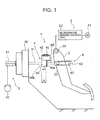
- FIG. 1 is a diagram illustrating the assembly of the regenerative braking coordination device 1 according to a first embodiment.
- the regenerative braking coordination device 1 includes a regenerative braking part 2 that generates braking force by means of regenerative braking by motor 21, a hydraulic braking part 3 and an input shaft 6 that transmits the operation amount input by a braking operating member, such as brake pedal 5, toward the side of hydraulic braking part 3.
- An operation amount absorbing part 4 absorbs the operation amount transmitted by input shaft 6.
- the regenerative braking part 2 includes an operation amount sensor 22 that detects the operation amount of brake pedal 5, regenerative braking control part 20 that controls the regenerative braking force according to the operation amount detected by operation amount sensor 22, and a motor 21 that generates the regenerative braking force according to control by the regenerative braking control part 20.
- the regenerative braking control part 20 is, for example, a standard microcomputer including a central processing unit (CPU) operating instructions stored in read-only memory (ROM) programmed to perform the functions described herein.
- CPU central processing unit
- ROM read-only memory
- the regenerative braking control part 20 is not limited to this and could be application-specific (ASIC) or hardware-implemented.
- the hydraulic braking part 3 includes an active booster 30, which generates an assisting force with respect to the operation force input to brake pedal 5, and at the same time, works as a hydraulic braking pressure generating source in the case of automatic braking control.
- a master cylinder 31 generates the hydraulic braking pressure
- wheel cylinders 32 generate the braking forces for the various wheels by means of the hydraulic braking pressure generated by master cylinder 31.
- the active booster 30 controls the supply quantities of atmospheric pressure and vacuum pressure from the engine.
- the active booster 30 also makes use of the pressure differential between atmospheric pressure and vacuum pressure to generate an assisting force with respect to the depression force input to the brake pedal 5.
- the active booster 30 controls the supply quantities of atmospheric pressure and vacuum pressure from the engine by means of an actuator, and it produces the force acting on the master cylinder 31 by means of the pressure differential between the atmospheric pressure and the vacuum pressure.
- a displacement amount locked to the operation of the active booster 30 is input to the input shaft 6.
- the operation amount absorbing part 4 includes a cylinder 40 with its interior filled with working fluid, a piston 41 that divides the interior of cylinder 40 into the first hydraulic chamber 40a and second hydraulic chamber 40b, a hydraulic channel 42 that connects first hydraulic chamber 40a and second hydraulic chamber 40b, and an orifice 43 arranged in the hydraulic channel 42.
- the piston 41 is arranged such that the axial dimension of the second hydraulic chamber 40b is distance (b) when no operation force is input to the brake pedal 5.
- the distance (b) is selected according to the operation amount of brake pedal 5 for performing braking only by means of regenerative braking when brake pedal 5 is operated slowly.
- the input shaft 6 includes a first input shaft 60 that connects piston 41 and brake pedal 5, a second input shaft 61 that connects active booster 30 and cylinder 40, and clevis 62 engaged to clevis pin 50 formed on brake pedal 5.
- Slot 63 is formed along the axial direction of input shaft 6 in clevis 62, and the latter is engaged to clevis pin 50 formed projecting from the side surface of brake pedal 5. Because clevis pin 50 is engaged in slot 63, brake pedal 5 does not move when active booster 30 operates despite the fact that a displacement is applied to input shaft 6.
- the regenerative braking and hydraulic braking are performed according to the operation amount of the brake pedal 5.
- the proportion of regenerative braking force with respect to the total braking force is selected to be higher until maximum regenerative braking force is obtained. Consequently, it is necessary to reduce braking generation by the hydraulic braking means.
- the operation speed of brake pedal 5 is high, it is necessary to generate the regenerative braking force and the hydraulic braking force from the range of a small operation amount of brake pedal 5 before maximum regenerative braking force is obtained. It is further desirable to improve the braking force generation response.
- input shaft 6 has an operation amount absorbing part 4 that works such that when the operation speed of brake pedal 5 is low, the absorption amount of the operation amount transmitted by input shaft 6 is increased, and when the operation speed of brake pedal 5 is high, the absorption amount of the operation amount transmitted by input shaft 6 is reduced.
- Piston 41 and brake pedal 5 are connected to each other by first input shaft 60.
- Active booster 30 and cylinder 40 are connected by second input shaft 61.
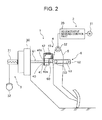
- FIG. 2 is a diagram illustrating the state of regenerative braking coordination device 1 when the operation speed of brake pedal 5 is low.
- the working fluid in second hydraulic chamber 40b moves through hydraulic channel 42 into first hydraulic chamber 40a when the first input shaft 60 presses piston 41. Consequently, although the operation amount is input from the brake pedal 5 to the first input shaft 60, the cylinder 40 does not move within the range of movement of the piston 41, so that the operation amount is not transmitted to the second input shaft 61.
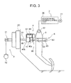
- FIG. 3 is a diagram illustrating the state of regenerative braking coordination device 1 when the operation speed of brake pedal 5 is high.
- the operation speed of the brake pedal 5 is high, although piston 41 is pressed by the first input shaft 60, the resistance in the orifice 43 prevents the working fluid from moving into the first hydraulic chamber 40a from the second hydraulic chamber 40b. Consequently, the piston 41 and cylinder 40 move together, so that the operation amount is transmitted from the first input shaft 60 to the second input shaft 61.
- the operation amount input to brake pedal 5 is transmitted to hydraulic braking part 3, the active booster 30 and master cylinder 31 are driven to move, and hydraulic braking is performed via the wheel cylinders 32.
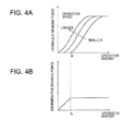
- FIGS. 4A and 4B are graphs illustrating the hydraulic braking force and regenerative braking force corresponding to the operation amount and operation speed. As shown in FIG. 4A , the higher the operation speed of brake pedal 5, the smaller the operation amount generated by the hydraulic braking force. On the other hand, as shown in FIG. 4B , the operation amount generated by the regenerative braking force is constant and independent of the operation speed of brake pedal 5.
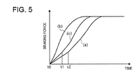
- FIG. 5 shows time charts illustrating the generation of the braking force when the operation speed of the brake pedal 5 is low and high, respectively, wherein (a) shows the state when the operation speed is low, (b) shows the state when the operation speed is high, and (c) shows the state when the operation speed is high when orifice 43 is not provided.
- the operation amount absorbing part 4 is provided to the input shaft 6 and functions so that when the operation amount of brake pedal 5 is lower, the absorption amount of the operation amount transmitted by the input shaft 6 is increased. Conversely, when the operation speed is higher, the absorption amount is decreased.
- the operation amount absorbing part 4 has a piston 41 that divides the interior of cylinder 40 into the first hydraulic chamber 40a and the second hydraulic chamber 40b.
- the operation amount absorbing part 4 also has a hydraulic channel 42 that connects first hydraulic chamber 40a and the second hydraulic chamber 40b, and an orifice 43 set in the hydraulic channel 42. Consequently, when the operation speed of brake pedal 5 is higher, because it is possible to set a smaller absorption amount transmitted by input shaft 6 and absorbed by the operation amount absorbing part 4, the regenerative braking force and hydraulic braking force can be generated earlier, and a high braking force can be generated with excellent responsiveness.
- FIG. 6 is a diagram illustrating the assembly of regenerative braking coordination device 1 according to the second embodiment. The same part numbers as those adopted in the first embodiment are adopted for the same structural parts, and they are not explained again.
- the switching valve 44 is arranged in the hydraulic channel 42 of the operation amount absorbing part 4. In the event of failure of the regenerative braking part 2 due to malfunctions or the like, the switching valve 44 is turned OFF so that the hydraulic channel 42 is blocked by the cutoff valve 44a. When the regenerative braking part 2 is in the normal state, the switching valve 44 is turned ON, and the hydraulic channel 42 is connected by the orifice 44b. That is, when regenerative braking part 2 fails, the hydraulic channel 42 is blocked by the cutoff valve 44a so that when brake pedal 5 is operated the working fluid does not move from the second hydraulic chamber 40b into the first hydraulic chamber 40a.
- a cutoff valve 44a is provided that blocks the hydraulic channel 42 when the regenerative braking part 2 fails.
- the slot 63 is formed in the clevis 62 along the axial direction of input shaft 6. Because the clevis pin 50 is engaged in slot 63, the brake pedal 5 does not move even when the input shaft 6 is displaced by operation of active booster 30. In the third embodiment, the operation amount absorbing part 4 prevents the brake pedal 5 from moving even when the active booster 30 works and a displacement is applied to the input shaft 6.
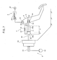
- FIG. 7 is a diagram illustrating the assembly of the regenerative braking coordination device 1 according to the third embodiment.
- the same part numbers as those adopted in the first and second embodiments are also adopted here to represent the same structural parts, and they are not explained again.
- the engagement aperture 64 engaged with the clevis pin 50 of the brake pedal 5 is formed in the clevis 62 of the input shaft 6.
- the clevis pin 50 is rotatably engaged in the engagement aperture 64.
- the operation amount absorbing part 4 is composed of a cylinder 45 filled with working fluid, a piston 41 that divides the interior of cylinder 45 into the first hydraulic chamber 45a and the second hydraulic chamber 45b, a hydraulic channel 42 that connects the first hydraulic chamber 45a and second hydraulic chamber 45b, and an orifice 43 set in the hydraulic channel 42.
- the piston 41 is arranged such that when the brake pedal 5 is not depressed, the axial dimension of first hydraulic chamber 45a is distance (a) and the axial dimension of second hydraulic chamber 45b is distance (b).
- the distance (a) is set to correspond to the displacement applied to second input shaft 61 in the automatic braking by the active booster 30, and distance (b) is set to correspond to the operation amount of the brake pedal 5 when braking is mainly performed only by regenerative braking in the normal braking operation.
- the active booster 30 automatically generates hydraulic braking pressure and creates a displacement of the input shaft 6 when the hydraulic braking pressure is generated automatically.
- the operation amount absorbing part 4 absorbs the operation amount transmitted by the input shaft 6 and the displacement of the input shaft 6 by the active booster 30.
- the operation amount absorbing part 4 prevents any force from acting on the side of the brake pedal 5 so that it is possible to prevent movement of the brake pedal 5.
- orifice 43 (or orifice 44b in the second embodiment) having equal forward and backward resistance to the working fluid is arranged in hydraulic channel 42.
- orifice 46 having different forward and backward resistances to the working fluid is arranged in the hydraulic channel 42. With respect to the speed with which brake pedal 5 is depressed, the speed of the return operation is lower, improving the operation fuel feel.
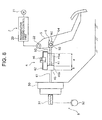
- FIG. 8 is a diagram illustrating the assembly of the regenerative braking coordination device 1 of the operation amount absorbing part 4 in the fourth embodiment.
- the same part numbers as those adopted in the previous embodiments are adopted to represent the same structural parts, and they are not explained again.
- FIGS. 9A and 9B are enlarged views of the orifice 46.
- a first channel 46a and a second channel 46b are formed as orifice 46.
- the first channel 46a has a cutoff valve 46c arranged therein.
- the valve 46c opens when the working fluid moves from the second hydraulic chamber 45b to the side of first hydraulic chamber 45a (forward), and the valve closes when the working fluid moves from the first hydraulic chamber 45a to the side of second hydraulic chamber 45b (backward).
- FIG. 9A the first channel 46a is blocked by cutoff valve 46c during the backward movement, and the working fluid passes only through second channel 46b.
- the first channel 46a is opened by cutoff valve 46c during the forward movement, and the working fluid passes through both the first channel 46a and the second channel 46b.
- the diameter of the orifice 46 for letting the working fluid pass through when brake pedal 5 performs the return operation is smaller than the diameter of orifice 46 for letting the working fluid pass through when the brake pedal 5 is depressed.
- the operation amount transmitted by the input shaft 6 is absorbed during the forward movement, so that the backward resistance is higher than the forward resistance. Consequently, it is possible to set the speed in the return operation to be lower than that when brake pedal 5 is depressed.
- the pair of first channel 46a and second channel 46b enable setting a smaller operation amount transmitted by the input shaft 6 and absorbed by operation amount absorbing part 4 when the operation speed of brake pedal 5 is higher. Consequently, regenerative braking force and hydraulic braking force are generated earlier, and it is possible to generate a high braking force with excellent responsiveness.
- the operation speed of brake pedal 5 is lower, it is possible to set a higher absorption amount transmitted by the input shaft 6 and absorbed by the operation amount absorbing part 4.
- the diameter for the backward side is selected to be smaller than that when the operation amount transmitted by input shaft 6 is absorbed. Consequently, it is possible to have the backward resistance be higher than the forward resistance, so that the speed in performing the return operation can be set lower than when brake pedal 5 is depressed and so that the operation feel can be improved.
- a regenerative braking coordination device 1 using an active booster 30 has been described as an example.
- a conventional brake boosting device can also be used as the active booster 30. That is, any regeneration brake and hydraulic brake using a brake boosting device may be adopted.
- the first input shaft 60 is connected to the piston 41 and the brake pedal 5, and second input shaft 61 is connected to the active booster 30 and cylinder 45 (or cylinder 40 in the first and second embodiments).
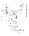
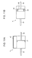
- the scheme shown in FIG. 10 can also be adopted for this assembly, in which the first input shaft 60 is connected to the cylinder 45 and brake pedal 5, and the second input shaft 61 is connected to the active booster 30 and piston 41.
- the operation amount absorbing part 4 is provided with a hydraulic channel 47 that connects the first hydraulic chamber 45a and second hydraulic chamber 45b.
- the diameter of hydraulic channel 47 is made narrow such that the effect of an orifice can be realized.
- a piston 48 that divides the interior into the first hydraulic chamber 45a and the second hydraulic chamber 45b is provided inside the cylinder 45.
- a narrow channel 48a for connecting the first hydraulic chamber 45a and the second hydraulic chamber 45b may be formed in piston 48 to exhibit the effect of the orifice.
- the effect of the regeneration braking coordination device 1 as show in Fig.11A, and 11B is explained hereinafter.
- the hydraulic channel 47 and the narrow channel 48a has the effect of an orifice when the operation speed of brake pedal 5 is higher. Consequently it is possible to miniaturize the operation amount absorbing part 4.
Landscapes
- Engineering & Computer Science (AREA)
- Transportation (AREA)
- Mechanical Engineering (AREA)
- Physics & Mathematics (AREA)
- Fluid Mechanics (AREA)
- Chemical & Material Sciences (AREA)
- Combustion & Propulsion (AREA)
- Regulating Braking Force (AREA)
- Braking Arrangements (AREA)
- Braking Elements And Transmission Devices (AREA)
Applications Claiming Priority (2)
| Application Number | Priority Date | Filing Date | Title |
|---|---|---|---|
| JP2007010894 | 2007-01-20 | ||
| JP2007333930A JP5125489B2 (ja) | 2007-01-20 | 2007-12-26 | 制動装置 |
Publications (3)
| Publication Number | Publication Date |
|---|---|
| EP1955914A2 true EP1955914A2 (de) | 2008-08-13 |
| EP1955914A3 EP1955914A3 (de) | 2015-08-26 |
| EP1955914B1 EP1955914B1 (de) | 2019-01-09 |
Family
ID=39540497
Family Applications (1)
| Application Number | Title | Priority Date | Filing Date |
|---|---|---|---|
| EP08150342.7A Ceased EP1955914B1 (de) | 2007-01-20 | 2008-01-17 | Koordinationsvorrichtung für regenerative Bremsen |
Country Status (2)
| Country | Link |
|---|---|
| US (1) | US8070239B2 (de) |
| EP (1) | EP1955914B1 (de) |
Cited By (4)
| Publication number | Priority date | Publication date | Assignee | Title |
|---|---|---|---|---|
| WO2010003517A3 (de) * | 2008-07-09 | 2010-03-25 | Lucas Automotive Gmbh | Bremskraftverstärker für eine kraftfahrzeugbremsanlage und entsprechende kraftfahrzeugbremsanlage |
| US7980002B2 (en) * | 2004-11-16 | 2011-07-19 | Röhren-und Pumpenwerk Bauer Gesellschaft mbH | Rotary drum for the aerobic heating of pourable solids |
| DE102010045005A1 (de) * | 2010-09-10 | 2012-03-15 | Iav Gmbh Ingenieurgesellschaft Auto Und Verkehr | Verfahren und Vorrichtung zum Bremsen eines Fahrzeuges |
| DE102011122205A1 (de) | 2011-12-23 | 2013-06-27 | Volkswagen Aktiengesellschaft | Verfahren und Vorrichtung zur Rekuperation bei Hybrid- oder Elektrofahrzeugen |
Families Citing this family (11)
| Publication number | Priority date | Publication date | Assignee | Title |
|---|---|---|---|---|
| IT1392621B1 (it) * | 2008-10-23 | 2012-03-16 | Ferrari Spa | Impianto frenante di un veicolo atto a comandare una frenata rigenerativa |
| FR2950592B1 (fr) | 2009-09-25 | 2011-09-23 | Michelin Soc Tech | Dispositif de freinage mixte a commande optimisee |
| DE102010040726A1 (de) * | 2010-09-14 | 2012-03-15 | Robert Bosch Gmbh | Verfahren zur Steuerung einer Bremsanlage eines Kraftfahrzeugs und Bremsanlage für ein Kraftfahrzeug |
| KR101338431B1 (ko) * | 2011-07-08 | 2013-12-10 | 현대자동차주식회사 | 자동차의 회생제동 시스템 |
| US8640796B2 (en) | 2012-05-11 | 2014-02-04 | Wzi, Inc. | Solar-powered quadricycle with regenerative and dissipative braking |
| KR101470149B1 (ko) * | 2013-04-30 | 2014-12-05 | 현대자동차주식회사 | 차량용 제동시스템의 고장 판단 방법 |
| US9776608B2 (en) | 2013-07-03 | 2017-10-03 | Ford Global Technologies, Llc | Enhanced regenerative braking control method for brake booster pressure build-up delay compensation |
| US9387833B1 (en) * | 2014-02-20 | 2016-07-12 | Daniel Theobald | Braking a rotatable power transfer device |
| US10351118B2 (en) * | 2015-08-26 | 2019-07-16 | Continental Automotive Systems, Inc. | System and method for reducing brake noise in a vehicle using electronic brake system |
| DE102018215653B4 (de) * | 2018-09-14 | 2025-04-10 | Hyundai Motor Company | Bremssystem zum Abbremsen eines Elektrofahrzeugs |
| GB2587240B (en) * | 2019-09-23 | 2021-12-08 | Transmon Eng Ltd | Braking Apparatus |
Citations (1)
| Publication number | Priority date | Publication date | Assignee | Title |
|---|---|---|---|---|
| JPH11171287A (ja) | 1997-12-08 | 1999-06-29 | Starlite Co Ltd | 大型基板用カセット |
Family Cites Families (12)
| Publication number | Priority date | Publication date | Assignee | Title |
|---|---|---|---|---|
| DE3814696A1 (de) * | 1988-04-30 | 1989-11-09 | Teves Gmbh Alfred | Schlupfgeregelte bremsanlage |
| DE3906528A1 (de) * | 1988-07-01 | 1990-01-04 | Teves Gmbh Alfred | Hydraulische kupplungseinrichtung, sowie bremsanlage mit einer derartigen kupplung |
| GB8920588D0 (en) * | 1989-09-12 | 1989-10-25 | Lucas Ind Plc | Improvements relating to a vacuum servo unit for use in traction control |
| DE3906529A1 (de) * | 1988-11-03 | 1990-09-06 | Teves Gmbh Alfred | Schlupfgeregelte bremsanlage |
| US5253929A (en) * | 1991-12-20 | 1993-10-19 | Toyota Jidosha Kabushiki Kaisha | Brake control system of electric vehicle |
| DE4200968A1 (de) * | 1992-01-16 | 1993-07-22 | Teves Gmbh Alfred | Blockiergeschuetzte hydaulische bremsanlage |
| JP3463707B2 (ja) | 1994-10-28 | 2003-11-05 | 株式会社ボッシュオートモーティブシステム | 電動車両の制動システム |
| DE19540705A1 (de) * | 1995-11-02 | 1997-05-07 | Continental Ag | Bremspedal zur Ansteuerung einer elektrischen Bremsanlage |
| JP3812224B2 (ja) | 1999-06-17 | 2006-08-23 | マツダ株式会社 | 車両の制動装置 |
| DE10260008A1 (de) * | 2002-12-13 | 2004-07-22 | Lucas Automotive Gmbh | Pedalsimulationseinrichtung |
| FR2874881B1 (fr) * | 2004-09-08 | 2006-12-15 | Bosch Gmbh Robert | Dispositif de freinage pour vehicule automobile |
| US7686404B2 (en) * | 2005-02-23 | 2010-03-30 | Continental Teves, Inc. | Electro-hydraulic braking system |
-
2008
- 2008-01-17 EP EP08150342.7A patent/EP1955914B1/de not_active Ceased
- 2008-01-17 US US12/015,549 patent/US8070239B2/en active Active
Patent Citations (1)
| Publication number | Priority date | Publication date | Assignee | Title |
|---|---|---|---|---|
| JPH11171287A (ja) | 1997-12-08 | 1999-06-29 | Starlite Co Ltd | 大型基板用カセット |
Cited By (6)
| Publication number | Priority date | Publication date | Assignee | Title |
|---|---|---|---|---|
| US7980002B2 (en) * | 2004-11-16 | 2011-07-19 | Röhren-und Pumpenwerk Bauer Gesellschaft mbH | Rotary drum for the aerobic heating of pourable solids |
| WO2010003517A3 (de) * | 2008-07-09 | 2010-03-25 | Lucas Automotive Gmbh | Bremskraftverstärker für eine kraftfahrzeugbremsanlage und entsprechende kraftfahrzeugbremsanlage |
| US9027340B2 (en) | 2008-07-09 | 2015-05-12 | Lucas Automotive Gmbh | Brake booster for an automotive brake system and corresponding automotive brake system |
| DE102010045005A1 (de) * | 2010-09-10 | 2012-03-15 | Iav Gmbh Ingenieurgesellschaft Auto Und Verkehr | Verfahren und Vorrichtung zum Bremsen eines Fahrzeuges |
| DE102010045005B4 (de) * | 2010-09-10 | 2015-04-30 | Iav Gmbh Ingenieurgesellschaft Auto Und Verkehr | Vorrichtung zum Bremsen eines Fahrzeuges |
| DE102011122205A1 (de) | 2011-12-23 | 2013-06-27 | Volkswagen Aktiengesellschaft | Verfahren und Vorrichtung zur Rekuperation bei Hybrid- oder Elektrofahrzeugen |
Also Published As
| Publication number | Publication date |
|---|---|
| EP1955914B1 (de) | 2019-01-09 |
| EP1955914A3 (de) | 2015-08-26 |
| US20080173490A1 (en) | 2008-07-24 |
| US8070239B2 (en) | 2011-12-06 |
Similar Documents
| Publication | Publication Date | Title |
|---|---|---|
| EP1955914A2 (de) | Koordinationsvorrichtung für regenerative Bremsen | |
| US8496301B2 (en) | Vehicle brake mechanism and method for controlling the vehicle brake mechanism | |
| US8827378B2 (en) | Brake apparatus | |
| US9802590B2 (en) | Brake system for motor vehicles | |
| US8544965B2 (en) | Brake system | |
| US8240780B1 (en) | Hydraulic brake booster | |
| JP2000142369A (ja) | ブレーキシステム | |
| JPS6320256A (ja) | マニユアル・電気二系統ブレ−キ装置 | |
| US20150001918A1 (en) | Brake system for vehicle designed to ensure stability in motion of brake pedal | |
| JP2008516830A (ja) | 自動車のブレーキ装置 | |
| US20150000266A1 (en) | Brake system for vehicle designed to improve mountability | |
| US20150001915A1 (en) | Brake system for vehicle designed to produce braking force with minimized delay | |
| JP3849583B2 (ja) | 電動ブレーキ装置 | |
| KR20070102715A (ko) | 차량의 브레이크 시스템 | |
| JP4794464B2 (ja) | 車輛の液圧式ブレーキシステム用の制動力発生器 | |
| JP5151081B2 (ja) | 車両用制動装置 | |
| US12280759B2 (en) | Vehicle brake system | |
| US7410223B2 (en) | Vehicle hydraulic brake device | |
| US8210091B2 (en) | Quick booster | |
| JP2009143302A (ja) | ストロークシミュレータ | |
| EP1101676B1 (de) | Verfahren und Vorrichtung zur Regelung der Bremskraft von Kraftfahrzeugen | |
| JP2003025985A (ja) | 車両用ブレーキ液圧発生装置、及び該液圧発生装置を備えた液圧ブレーキ装置 | |
| JP2009161130A (ja) | ブレーキ装置 | |
| US20240101093A1 (en) | Vehicle brake system | |
| JP2010215069A (ja) | Bbw式ブレーキ装置 |
Legal Events
| Date | Code | Title | Description |
|---|---|---|---|
| PUAI | Public reference made under article 153(3) epc to a published international application that has entered the european phase |
Free format text: ORIGINAL CODE: 0009012 |
|
| AK | Designated contracting states |
Kind code of ref document: A2 Designated state(s): AT BE BG CH CY CZ DE DK EE ES FI FR GB GR HR HU IE IS IT LI LT LU LV MC MT NL NO PL PT RO SE SI SK TR |
|
| AX | Request for extension of the european patent |
Extension state: AL BA MK RS |
|
| PUAL | Search report despatched |
Free format text: ORIGINAL CODE: 0009013 |
|
| AK | Designated contracting states |
Kind code of ref document: A3 Designated state(s): AT BE BG CH CY CZ DE DK EE ES FI FR GB GR HR HU IE IS IT LI LT LU LV MC MT NL NO PL PT RO SE SI SK TR |
|
| AX | Request for extension of the european patent |
Extension state: AL BA MK RS |
|
| RIC1 | Information provided on ipc code assigned before grant |
Ipc: B60T 13/58 20060101AFI20150721BHEP Ipc: B60T 8/38 20060101ALI20150721BHEP Ipc: B60T 7/04 20060101ALI20150721BHEP |
|
| 17P | Request for examination filed |
Effective date: 20151203 |
|
| RBV | Designated contracting states (corrected) |
Designated state(s): AT BE BG CH CY CZ DE DK EE ES FI FR GB GR HR HU IE IS IT LI LT LU LV MC MT NL NO PL PT RO SE SI SK TR |
|
| AKX | Designation fees paid |
Designated state(s): DE FR GB |
|
| AXX | Extension fees paid |
Extension state: BA Extension state: MK Extension state: AL Extension state: RS |
|
| GRAP | Despatch of communication of intention to grant a patent |
Free format text: ORIGINAL CODE: EPIDOSNIGR1 |
|
| INTG | Intention to grant announced |
Effective date: 20181017 |
|
| GRAS | Grant fee paid |
Free format text: ORIGINAL CODE: EPIDOSNIGR3 |
|
| GRAA | (expected) grant |
Free format text: ORIGINAL CODE: 0009210 |
|
| AK | Designated contracting states |
Kind code of ref document: B1 Designated state(s): DE FR GB |
|
| REG | Reference to a national code |
Ref country code: GB Ref legal event code: FG4D |
|
| REG | Reference to a national code |
Ref country code: DE Ref legal event code: R096 Ref document number: 602008058665 Country of ref document: DE |
|
| REG | Reference to a national code |
Ref country code: DE Ref legal event code: R097 Ref document number: 602008058665 Country of ref document: DE |
|
| PLBE | No opposition filed within time limit |
Free format text: ORIGINAL CODE: 0009261 |
|
| STAA | Information on the status of an ep patent application or granted ep patent |
Free format text: STATUS: NO OPPOSITION FILED WITHIN TIME LIMIT |
|
| 26N | No opposition filed |
Effective date: 20191010 |
|
| REG | Reference to a national code |
Ref country code: DE Ref legal event code: R084 Ref document number: 602008058665 Country of ref document: DE |
|
| REG | Reference to a national code |
Ref country code: GB Ref legal event code: 746 Effective date: 20231024 |
|
| PGFP | Annual fee paid to national office [announced via postgrant information from national office to epo] |
Ref country code: GB Payment date: 20231219 Year of fee payment: 17 |
|
| PGFP | Annual fee paid to national office [announced via postgrant information from national office to epo] |
Ref country code: FR Payment date: 20231219 Year of fee payment: 17 |
|
| PGFP | Annual fee paid to national office [announced via postgrant information from national office to epo] |
Ref country code: DE Payment date: 20231219 Year of fee payment: 17 |
|
| REG | Reference to a national code |
Ref country code: DE Ref legal event code: R119 Ref document number: 602008058665 Country of ref document: DE |
|
| GBPC | Gb: european patent ceased through non-payment of renewal fee |
Effective date: 20250117 |
|
| PG25 | Lapsed in a contracting state [announced via postgrant information from national office to epo] |
Ref country code: DE Free format text: LAPSE BECAUSE OF NON-PAYMENT OF DUE FEES Effective date: 20250801 |
|
| PG25 | Lapsed in a contracting state [announced via postgrant information from national office to epo] |
Ref country code: GB Free format text: LAPSE BECAUSE OF NON-PAYMENT OF DUE FEES Effective date: 20250117 |
|
| PG25 | Lapsed in a contracting state [announced via postgrant information from national office to epo] |
Ref country code: FR Free format text: LAPSE BECAUSE OF NON-PAYMENT OF DUE FEES Effective date: 20250131 |