EP1955923A2 - Zusammenschiebbare Lenksäulenhaltevorrichtung - Google Patents
Zusammenschiebbare Lenksäulenhaltevorrichtung Download PDFInfo
- Publication number
- EP1955923A2 EP1955923A2 EP20080150711 EP08150711A EP1955923A2 EP 1955923 A2 EP1955923 A2 EP 1955923A2 EP 20080150711 EP20080150711 EP 20080150711 EP 08150711 A EP08150711 A EP 08150711A EP 1955923 A2 EP1955923 A2 EP 1955923A2
- Authority
- EP
- European Patent Office
- Prior art keywords
- column jacket
- assembly
- rake
- mounting bracket
- rod
- Prior art date
- Legal status (The legal status is an assumption and is not a legal conclusion. Google has not performed a legal analysis and makes no representation as to the accuracy of the status listed.)
- Granted
Links
- 230000007246 mechanism Effects 0.000 claims abstract description 29
- 230000014759 maintenance of location Effects 0.000 claims description 9
- 239000002775 capsule Substances 0.000 claims description 4
- 230000000712 assembly Effects 0.000 description 2
- 238000000429 assembly Methods 0.000 description 2
- 239000002184 metal Substances 0.000 description 1
- 230000004048 modification Effects 0.000 description 1
- 238000012986 modification Methods 0.000 description 1
- 230000000452 restraining effect Effects 0.000 description 1
Images


Classifications
-
- B—PERFORMING OPERATIONS; TRANSPORTING
- B62—LAND VEHICLES FOR TRAVELLING OTHERWISE THAN ON RAILS
- B62D—MOTOR VEHICLES; TRAILERS
- B62D1/00—Steering controls, i.e. means for initiating a change of direction of the vehicle
- B62D1/02—Steering controls, i.e. means for initiating a change of direction of the vehicle vehicle-mounted
- B62D1/16—Steering columns
- B62D1/18—Steering columns yieldable or adjustable, e.g. tiltable
- B62D1/19—Steering columns yieldable or adjustable, e.g. tiltable incorporating energy-absorbing arrangements, e.g. by being yieldable or collapsible
- B62D1/195—Yieldable supports for the steering column
-
- B—PERFORMING OPERATIONS; TRANSPORTING
- B62—LAND VEHICLES FOR TRAVELLING OTHERWISE THAN ON RAILS
- B62D—MOTOR VEHICLES; TRAILERS
- B62D1/00—Steering controls, i.e. means for initiating a change of direction of the vehicle
- B62D1/02—Steering controls, i.e. means for initiating a change of direction of the vehicle vehicle-mounted
- B62D1/16—Steering columns
- B62D1/18—Steering columns yieldable or adjustable, e.g. tiltable
- B62D1/184—Mechanisms for locking columns at selected positions
-
- Y—GENERAL TAGGING OF NEW TECHNOLOGICAL DEVELOPMENTS; GENERAL TAGGING OF CROSS-SECTIONAL TECHNOLOGIES SPANNING OVER SEVERAL SECTIONS OF THE IPC; TECHNICAL SUBJECTS COVERED BY FORMER USPC CROSS-REFERENCE ART COLLECTIONS [XRACs] AND DIGESTS
- Y10—TECHNICAL SUBJECTS COVERED BY FORMER USPC
- Y10T—TECHNICAL SUBJECTS COVERED BY FORMER US CLASSIFICATION
- Y10T292/00—Closure fasteners
- Y10T292/06—Adjustable backset
Definitions
- the subject invention generally relates to a collapsible steering column assembly having a rake adjustment for a vehicle, and more specifically to supporting the steering column assembly post-collapse of the steering column assembly.
- the collapsible steering column assembly includes a mounting bracket that attaches a column jacket to a vehicle.
- the column jacket is pivotable about a rake axis, and is supported in an elevated position by a rake bracket prior to collapse of the steering column assembly to prevent the column jacket from rotating downward onto a driver of the vehicle.
- the steering column assembly further includes a support mechanism that supports the column jacket in the elevated position after it has been collapsed as a result of an emergency event to prevent the column jacket from pivoting about the rake axis and falling onto a driver of the vehicle after collapse of the steering column assembly.
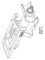
- the support mechanism is integrated into the mounting bracket, as is shown in Prior Art Figures 1 and 2 .
- the steering column assembly includes the rake bracket connected to the mounting bracket by a plurality of rivets.
- the mounting bracket includes a plurality of slots, with each of the rivets disposed in one of the slots.
- the mounting bracket includes a lip for supporting edges of the rake bracket.
- the edges of the rake bracket slide along the lip of the mounting bracket. Accordingly, the rake bracket and the column jacket are supported in the elevated position both pre-collapse and post-collapse of the steering column assembly.
- the subject invention provides a steering column assembly for a vehicle.
- the steering column assembly comprises a mounting bracket for attaching the steering column assembly to the vehicle.
- a column jacket is connected to the mounting bracket, and is longitudinally moveable relative to the mounting bracket along a longitudinal axis in response to an emergency event.
- the column jacket is also pivotally moveable relative to the mounting bracket about a rake axis.
- a rake bracket is coupled to the column jacket, and spaced from the mounting bracket along the longitudinal axis.
- the rake bracket attaches the column jacket to the vehicle in an elevated position prior to the emergency event, and is detachable from the vehicle in response to the longitudinal movement of the column jacket in response to the emergency event.
- a support mechanism is interconnected between the mounting bracket and the column jacket. The support mechanism pivots with the column jacket during the pivotal movement, and supports the column jacket in the elevated position after detachment of the rake bracket from the vehicle in response to the emergency event.
- the subject invention provides a support mechanism for supporting the column jacket in the elevated position after collapse of the steering column assembly.
- the support mechanism pivots with the column jacket as an operator of the vehicle adjusts the height of the steering column assembly, which permits the size of the mounting bracket to be reduced, thereby minimizing the cost of producing the steering column assembly.
- Figure 3 is a perspective view of a steering column assembly in a pre-collapse state
- Figure 4 is an enlarged perspective view of a clamp of a support mechanism in the pre-collapse state of the steering column assembly
- Figure 5 is a perspective view of the steering column assembly in a post-collapse state.
- Figure 6 is a side view of the steering column assembly in the post-collapse state.
- a steering column assembly is generally shown at 20.
- the steering column assembly 20 is for a vehicle, and is collapsible in response to an emergency event as is well known in the art. Additionally, the steering column assembly 20 includes a rake adjustment mechanism shown generally at 22 for adjusting the height of the steering column within the vehicle as is also well known in the art.
- the steering column assembly 20 includes a mounting bracket 24 for attachment to the vehicle.
- the mounting bracket 24 is attached to a support structure by a fastener, such as a bolt, within the vehicle.
- the mounting bracket 24 may be attached to the vehicle in any number of ways known to those skilled in the art.
- a column jacket 26 is connected to the mounting bracket 24, and is longitudinally moveable relative to the mounting bracket 24 along a longitudinal axis L.
- the column jacket 26 supports a steering column shaft 28 therein as is well known in the art.
- the column jacket 26 moves along the longitudinal axis L in response to an emergency event.
- the column jacket 26 is also pivotally moveable relative to the mounting bracket 24 about a rake axis R. As is known in the art, the column jacket 26 pivots about the rake axis R to adjust the height of the column jacket 26, and thereby the position of a steering wheel within the vehicle.
- a pin 30 interconnects the mounting bracket 24 and the column jacket 26, with the column jacket 26 defining a slot 32 extending parallel the longitudinal axis L.
- the slot 32 receives the pin 30 therethrough to permit slideable movement between the mounting bracket 24 and the column jacket 26, thereby permitting the steering column to collapse in response to the emergency event.
- the pin 30 defines the rake axis R, with a central axis of the pin 30 being concentric with the rake axis R.
- the steering column assembly 20 may be configured otherwise than as described herein and that the rake axis R may be defined by some other feature of the steering column assembly 20.
- a rake bracket 34 is coupled to the column jacket 26 and spaced from the mounting bracket 24 along the longitudinal axis L.
- the rake bracket 34 attaches the column jacket 26 to the vehicle in an elevated position prior to the emergency event, and is detachable from the vehicle in response to the longitudinal movement of the column jacket 26 in response to the emergency event.
- a release capsule 36 is disposed on the rake bracket 34, and releasably interconnects the rake bracket 34 to the vehicle.
- the release capsule 36 is releasably attached to the rake bracket 34, and typically includes an aperture for passing a fastener therethrough to connect the rake bracket 34 to the vehicle.
- the release capsule 36 and the fastener disposed therethrough detach from the rake bracket 34, no longer attaching the rake bracket 34 to the vehicle. Accordingly, the rake bracket 34 supports the column jacket 26 in the elevated position pre-collapse of the steering column assembly 20, but does not support the column jacket 26 in the elevated position post-collapse of the steering column assembly 20.
- the elevated position of the column jacket 26 refers to the normal operating position of the steering column assembly 20. Failure to support the column jacket 26 in the elevated position post-collapse of the steering column assembly 20 would result in the column jacket 26, and the steering wheel, rotating about the rake axis R onto an operator of the vehicle.
- the steering column assembly 20 includes a support mechanism generally shown at 40, interconnected between the mounting bracket 24 and the column jacket 26.
- the support mechanism 40 pivots with the column jacket 26 during the pivotal movement of the column jacket 26, and supports the column jacket 26 in the elevated position after detachment of the rake bracket 34 from the vehicle in response to the emergency event.
- the support mechanism 40 includes a rod 42 coupled to one of the column jacket 26 and the mounting bracket 24, and a clamp 44 coupled to the other of the column jacket 26 and the mounting bracket 24.
- the rod 42 and the clamp 44 interconnect the column jacket 26 and the mounting bracket 24, and are longitudinally moveable relative to each other.
- a first pivotal connection 46 interconnects the support mechanism 40 and the column jacket 26, and a second pivotal connection 48 interconnects the support mechanism 40 and the mounting bracket 24.
- the rod 42 is coupled to the column jacket 26 for longitudinal movement with the column jacket 26.
- the first pivotal connection 46 interconnects the column jacket 26 and the rod 42, with the rod 42 defining a pivot point about which the rod 42 pivots relative to the column jacket 26.
- the rod 42 moves along a path in a non-intersecting relationship relative to the rake axis R in response to the emergency event.
- the clamp 44 is preferably stationary relative to the mounting bracket 24 and is in spaced relationship relative to the rake axis R.
- the rod 42 is in slideable engagement with the clamp 44 for one-way movement of the rod 42 relative to the clamp 44 as the rod 42 moves longitudinally along the longitudinal axis L during the emergency event.
- the clamp 44 is coupled to the mounting bracket 24.
- the second pivotal connection 48 interconnects the clamp 44 and the mounting bracket 24.
- the clamp 44 may be coupled to some other feature of the vehicle or steering column assembly 20, so long as it is stationary during the collapse of the steering column assembly 20, i.e., in response the emergency event, the column jacket 26 moves relative to the clamp 44.
- the clamp 44 may be coupled to the steering jacket, in which case the first pivotal connection 46 interconnects the clamp 44 and the column jacket 26;
- the rod 42 may be coupled to the mounting jacket, in which case the second pivotal connection 48 interconnects the rod 42 and the mounting bracket 24. It should be understood that when the rod 42 is coupled to the mounting bracket 24 and the clamp 44 coupled to the steering jacket that the rod 42 is stationary relative to the mounting bracket 24, and the clamp 44 moves longitudinally with the steering jacket relative to the rod 42.
- the clamp 44 includes a retention device 50 for allowing longitudinal movement of the rod 42 in a single direction in response to the emergency event to hold the rod 42 in place after the emergency event.
- the clamp 44 includes a housing 52 defining a bore 38 having a first section 54 and a second section 56.
- the retention device 50 includes a non-slip washer 58 disposed between the first section 54 and the second section 56 of the bore 38 for permitting longitudinal movement of the rod 42 in a single direction only.
- the non-slip washer 58 includes a plurality of teeth 60 for engaging the rod 42.
- the rod 42 includes a distal end 62, which is disposed within the first section 54 of the bore 38 prior to detachment of the rake bracket 34 from the vehicle.
- the distal end 62 of the rod 42 advances through the clamp 44, engaging the retention device 50 upon the collapse of the steering column assembly 20. Accordingly, the steering column assembly 20 is free to rotate about the rake axis R prior to detachment of the rake bracket 34 from the vehicle, and is prevented from rotation about the rake axis R after detachment of the rake bracket 34 from the vehicle, i.e., after collapse of the steering column assembly 20, the rod 42 advances through the clamp 44, with the clamp 44 restraining the rod 42 from backward movement, thereby supporting the column jacket 26 in the elevated position. It should be understood that the clamp 44 and the retention device 50 may be otherwise configured than as described herein to permit one-way movement of the rod 42 relative to the clamp 44 and still fall within the scope of the claims.
- the support mechanism 40 moves longitudinally along the longitudinal axis L in a non-intersecting relationship with the rake axis R, with the rake axis R and the second pivotal connection 48 stationary relative to the first pivotal connection 46. Accordingly, when viewed from the side, the first pivotal connection 46, the second pivotal connection 48, and the rake axis R form the vertices of a triangle. As such, because the rake axis R and the second pivotal connection 48 remain stationary, the only way for the column jacket 26 to rotate about the rake axis R after the rod 42 has advanced through the clamp 44, as a result of the emergency event, would be for the rod 42 to withdraw backwards through the clamp 44.
- the clamp 44 limits the movement of the rod 42 to a single direction, the rod 42 is unable to withdraw through the clamp 44 in the opposite direction. Accordingly, the steering jacket is unable to rotate about the rake axis R, and thereby supported in the elevated position post-collapse.
- the steering column further comprises a biasing device 64, which interconnects the column jacket 26 and the rake bracket 34.
- the biasing device 64 continuously biases the column jacket 26 toward the rake bracket 34.
- the biasing device 64 is preferably a coil spring, but may include some other device capable of urging the column jacket 26 against the rake bracket 34. After the rake bracket 34 is detached upon the emergency event, the biasing device 64 continues to urge the steering jacket against the rake bracket 34.
- the biasing device 64 assists the rake adjustment mechanism 22, and provides and upward lift prior to detachment of the rake bracket 34 from the vehicle to prevent the steering jacket from dropping onto the operator of the vehicle while the operator is using the rake adjustment mechanism 22.
- the rake adjustment mechanism 22 operates prior to the emergency event and pre-collapse of the steering column assembly 20 to release the steering jacket temporarily to adjust the height of the steering wheel. After which, the rake adjustment mechanism 22 secures the steering jacket in the desired position.
- rake adjustment mechanisms 22 There are many configurations of rake adjustment mechanisms 22 known in the art, which may be installed and utilized on the above described steering column assembly 20. Accordingly, the rake adjustment mechanism 22 is not specifically described herein.
- the steering column assembly 20 may further comprises an energy absorbing device (not shown) for absorbing energy from the column jacket 26 in response to the longitudinal movement of the column jacket 26 during the emergency event.
- the energy absorbing device dissipates energy transmitted through the steering column assembly 20 as a result of the emergency event, typically be deforming a metal strip.
- energy absorbing devices 50, 64 known in the art which may be installed and utilized on the above described steering column assembly 20, Accordingly, the exact configuration of the energy absorbing device is not specifically described herein.
Landscapes
- Engineering & Computer Science (AREA)
- Chemical & Material Sciences (AREA)
- Combustion & Propulsion (AREA)
- Transportation (AREA)
- Mechanical Engineering (AREA)
- Steering Controls (AREA)
Applications Claiming Priority (1)
| Application Number | Priority Date | Filing Date | Title |
|---|---|---|---|
| US11/702,885 US7625009B2 (en) | 2007-02-06 | 2007-02-06 | Collapsible steering column support |
Publications (3)
| Publication Number | Publication Date |
|---|---|
| EP1955923A2 true EP1955923A2 (de) | 2008-08-13 |
| EP1955923A3 EP1955923A3 (de) | 2009-06-24 |
| EP1955923B1 EP1955923B1 (de) | 2011-06-15 |
Family
ID=39358094
Family Applications (1)
| Application Number | Title | Priority Date | Filing Date |
|---|---|---|---|
| EP20080150711 Not-in-force EP1955923B1 (de) | 2007-02-06 | 2008-01-28 | Zusammenschiebbare Lenksäulenhaltevorrichtung |
Country Status (3)
| Country | Link |
|---|---|
| US (1) | US7625009B2 (de) |
| EP (1) | EP1955923B1 (de) |
| CN (1) | CN201604685U (de) |
Cited By (2)
| Publication number | Priority date | Publication date | Assignee | Title |
|---|---|---|---|---|
| EP2366602A3 (de) * | 2010-03-19 | 2012-01-18 | JTEKT Corporation | Lenkvorrichtung |
| EP2366601A3 (de) * | 2010-03-19 | 2012-01-25 | Jtekt Corporation | Lenkvorrichtung |
Families Citing this family (6)
| Publication number | Priority date | Publication date | Assignee | Title |
|---|---|---|---|---|
| DE102007028770B4 (de) * | 2007-06-22 | 2019-08-14 | Dr. Ing. H.C. F. Porsche Aktiengesellschaft | Lenksäulenanordnung für ein Kraftfahrzeug |
| US8702126B2 (en) * | 2012-02-15 | 2014-04-22 | Ford Global Technologies, Llc | Device for secondary energy management in a steering column assembly |
| GB201303513D0 (en) * | 2013-02-27 | 2013-04-10 | Trw Ltd | A steering column assembly |
| CN105015613A (zh) * | 2015-08-12 | 2015-11-04 | 安徽江淮汽车股份有限公司 | 一种汽车转向管柱总成及其拉脱结构 |
| US11465681B2 (en) * | 2019-04-12 | 2022-10-11 | Steering Solutions Ip Holding Corporation | Position identification assembly for steering column |
| US12448025B2 (en) * | 2023-07-05 | 2025-10-21 | Steering Solutions Ip Holding Corporation | Steer-by-wire steering column |
Family Cites Families (11)
| Publication number | Priority date | Publication date | Assignee | Title |
|---|---|---|---|---|
| US4602520A (en) * | 1983-06-23 | 1986-07-29 | Aisin Seiki Kabushiki Kaisha | Telescopic steering column assembly |
| US5081879A (en) * | 1990-05-24 | 1992-01-21 | Ford Motor Company | Steering column assembly mounting bracket |
| JPH11115770A (ja) * | 1997-10-09 | 1999-04-27 | Mitsubishi Motors Corp | 衝撃吸収式ステアリングコラム支持構造 |
| US6176151B1 (en) * | 1999-05-06 | 2001-01-23 | Delphi Technologies, Inc. | Connection for energy absorbing steering column |
| DE60133331T3 (de) * | 2000-02-15 | 2012-12-06 | Nsk Ltd. | Lenkung für ein Automobil |
| JP3933409B2 (ja) * | 2001-03-29 | 2007-06-20 | 株式会社ジェイテクト | 舵取装置 |
| US6659504B2 (en) | 2001-05-18 | 2003-12-09 | Delphi Technologies, Inc. | Steering column for a vehicle |
| JP4218379B2 (ja) * | 2002-07-11 | 2009-02-04 | 日本精工株式会社 | 車両用チルト式ステアリング装置 |
| JP4331974B2 (ja) * | 2003-05-15 | 2009-09-16 | 三菱自動車工業株式会社 | ステアリングコラム支持装置 |
| JP4354762B2 (ja) * | 2003-09-01 | 2009-10-28 | 日本精工株式会社 | 車両用位置調整式ステアリングコラム装置 |
| JP4210853B2 (ja) * | 2004-06-16 | 2009-01-21 | 三菱自動車工業株式会社 | 車両のステアリング支持装置 |
-
2007
- 2007-02-06 US US11/702,885 patent/US7625009B2/en not_active Expired - Fee Related
-
2008
- 2008-01-28 EP EP20080150711 patent/EP1955923B1/de not_active Not-in-force
- 2008-02-05 CN CN2008200060676U patent/CN201604685U/zh not_active Expired - Fee Related
Non-Patent Citations (1)
| Title |
|---|
| None |
Cited By (4)
| Publication number | Priority date | Publication date | Assignee | Title |
|---|---|---|---|---|
| EP2366602A3 (de) * | 2010-03-19 | 2012-01-18 | JTEKT Corporation | Lenkvorrichtung |
| EP2366601A3 (de) * | 2010-03-19 | 2012-01-25 | Jtekt Corporation | Lenkvorrichtung |
| US8485554B2 (en) | 2010-03-19 | 2013-07-16 | Jtekt Corporation | Steering device |
| US8651526B2 (en) | 2010-03-19 | 2014-02-18 | Jtekt Corporation | Steering apparatus |
Also Published As
| Publication number | Publication date |
|---|---|
| US7625009B2 (en) | 2009-12-01 |
| EP1955923A3 (de) | 2009-06-24 |
| EP1955923B1 (de) | 2011-06-15 |
| CN201604685U (zh) | 2010-10-13 |
| US20080185830A1 (en) | 2008-08-07 |
Similar Documents
| Publication | Publication Date | Title |
|---|---|---|
| US7625009B2 (en) | Collapsible steering column support | |
| US6347778B1 (en) | Vertical seat positioning device | |
| US8167502B2 (en) | Steering column assembly | |
| US8419102B2 (en) | Cargo net device | |
| US10300938B2 (en) | Steering column assembly | |
| US8197007B2 (en) | Combination pivotal and displaceable headrest assembly incorporated into a vehicle seat | |
| US6272945B1 (en) | Tilt release system for a steering column | |
| EP1728702A1 (de) | Adaptiver Energieabsorber für eine Lenksäule | |
| EP3225504A1 (de) | Lenksäulenvorrichtung | |
| TW201514054A (zh) | 自行車操作裝置 | |
| EP1510433B1 (de) | Schwenkbare lenksäulenvorrichtung für fahrzeug | |
| CN108528626B (zh) | 自行车操作装置 | |
| US10259533B2 (en) | Bicycle operating device | |
| US7798037B2 (en) | Wedge arm positive rake lock | |
| US6205882B1 (en) | Tilt release system for a steering column | |
| WO2025030211A1 (en) | Mount for a handheld electronic device | |
| US7484810B2 (en) | Armrest apparatus | |
| CN108068990B (zh) | 自行车部件操作装置 | |
| US20050017492A1 (en) | Steering column linkage tilt lever | |
| US20120080918A1 (en) | Self-leveling armrest assembly | |
| JP2009061993A (ja) | チルトテレスコ・ステアリング装置 | |
| US9592880B2 (en) | Bicycle operating apparatus | |
| EP0967112A3 (de) | Neigungsverstellmechanismus für Fahrzeugsitze | |
| US20080229872A1 (en) | Adjustable pedal assembly | |
| JP2008273350A (ja) | ウォークイン機構付きシートリクライニング装置 |
Legal Events
| Date | Code | Title | Description |
|---|---|---|---|
| PUAI | Public reference made under article 153(3) epc to a published international application that has entered the european phase |
Free format text: ORIGINAL CODE: 0009012 |
|
| AK | Designated contracting states |
Kind code of ref document: A2 Designated state(s): AT BE BG CH CY CZ DE DK EE ES FI FR GB GR HR HU IE IS IT LI LT LU LV MC MT NL NO PL PT RO SE SI SK TR |
|
| AX | Request for extension of the european patent |
Extension state: AL BA MK RS |
|
| PUAL | Search report despatched |
Free format text: ORIGINAL CODE: 0009013 |
|
| AK | Designated contracting states |
Kind code of ref document: A3 Designated state(s): AT BE BG CH CY CZ DE DK EE ES FI FR GB GR HR HU IE IS IT LI LT LU LV MC MT NL NO PL PT RO SE SI SK TR |
|
| AX | Request for extension of the european patent |
Extension state: AL BA MK RS |
|
| 17P | Request for examination filed |
Effective date: 20091222 |
|
| 17Q | First examination report despatched |
Effective date: 20100203 |
|
| AKX | Designation fees paid |
Designated state(s): DE FR IT |
|
| GRAP | Despatch of communication of intention to grant a patent |
Free format text: ORIGINAL CODE: EPIDOSNIGR1 |
|
| RAP1 | Party data changed (applicant data changed or rights of an application transferred) |
Owner name: GM GLOBAL TECHNOLOGY OPERATIONS, INC. |
|
| GRAS | Grant fee paid |
Free format text: ORIGINAL CODE: EPIDOSNIGR3 |
|
| GRAA | (expected) grant |
Free format text: ORIGINAL CODE: 0009210 |
|
| AK | Designated contracting states |
Kind code of ref document: B1 Designated state(s): DE FR IT |
|
| RAP2 | Party data changed (patent owner data changed or rights of a patent transferred) |
Owner name: GM GLOBAL TECHNOLOGY OPERATIONS LLC |
|
| REG | Reference to a national code |
Ref country code: DE Ref legal event code: R096 Ref document number: 602008007555 Country of ref document: DE Effective date: 20110804 |
|
| PLBE | No opposition filed within time limit |
Free format text: ORIGINAL CODE: 0009261 |
|
| STAA | Information on the status of an ep patent application or granted ep patent |
Free format text: STATUS: NO OPPOSITION FILED WITHIN TIME LIMIT |
|
| 26N | No opposition filed |
Effective date: 20120316 |
|
| PG25 | Lapsed in a contracting state [announced via postgrant information from national office to epo] |
Ref country code: IT Free format text: LAPSE BECAUSE OF FAILURE TO SUBMIT A TRANSLATION OF THE DESCRIPTION OR TO PAY THE FEE WITHIN THE PRESCRIBED TIME-LIMIT Effective date: 20110615 |
|
| REG | Reference to a national code |
Ref country code: DE Ref legal event code: R097 Ref document number: 602008007555 Country of ref document: DE Effective date: 20120316 |
|
| REG | Reference to a national code |
Ref country code: DE Ref legal event code: R082 Ref document number: 602008007555 Country of ref document: DE Representative=s name: MANITZ, FINSTERWALD & PARTNER GBR, DE Ref country code: FR Ref legal event code: ST Effective date: 20120928 |
|
| REG | Reference to a national code |
Ref country code: DE Ref legal event code: R082 Ref document number: 602008007555 Country of ref document: DE Representative=s name: MANITZ, FINSTERWALD & PARTNER GBR, DE Effective date: 20121019 Ref country code: DE Ref legal event code: R081 Ref document number: 602008007555 Country of ref document: DE Owner name: STEERING SOLUTIONS IP HOLDING CORP., US Free format text: FORMER OWNER: GM GLOBAL TECHNOLOGY OPERATIONS, INC., DETROIT, US Effective date: 20121019 Ref country code: DE Ref legal event code: R081 Ref document number: 602008007555 Country of ref document: DE Owner name: GM GLOBAL TECHNOLOGY OPERATIONS LLC (N. D. GES, US Free format text: FORMER OWNER: GM GLOBAL TECHNOLOGY OPERATIONS, INC., DETROIT, US Effective date: 20121019 Ref country code: DE Ref legal event code: R081 Ref document number: 602008007555 Country of ref document: DE Owner name: STEERING SOLUTIONS IP HOLDING CORP., SAGINAW, US Free format text: FORMER OWNER: GM GLOBAL TECHNOLOGY OPERATIONS, INC., DETROIT, MICH., US Effective date: 20121019 Ref country code: DE Ref legal event code: R081 Ref document number: 602008007555 Country of ref document: DE Owner name: GM GLOBAL TECHNOLOGY OPERATIONS LLC (N. D. GES, US Free format text: FORMER OWNER: GM GLOBAL TECHNOLOGY OPERATIONS, INC., DETROIT, MICH., US Effective date: 20121019 |
|
| PG25 | Lapsed in a contracting state [announced via postgrant information from national office to epo] |
Ref country code: FR Free format text: LAPSE BECAUSE OF NON-PAYMENT OF DUE FEES Effective date: 20120131 |
|
| REG | Reference to a national code |
Ref country code: DE Ref legal event code: R082 Ref document number: 602008007555 Country of ref document: DE Representative=s name: MANITZ, FINSTERWALD & PARTNER GBR, DE |
|
| PGFP | Annual fee paid to national office [announced via postgrant information from national office to epo] |
Ref country code: DE Payment date: 20130129 Year of fee payment: 6 |
|
| REG | Reference to a national code |
Ref country code: DE Ref legal event code: R082 Ref document number: 602008007555 Country of ref document: DE Representative=s name: MANITZ, FINSTERWALD & PARTNER GBR, DE Effective date: 20130313 Ref country code: DE Ref legal event code: R081 Ref document number: 602008007555 Country of ref document: DE Owner name: STEERING SOLUTIONS IP HOLDING CORP., US Free format text: FORMER OWNER: GM GLOBAL TECHNOLOGY OPERATIONS LLC (N. D. GES. D. STAATES DELAWARE), DETROIT, US Effective date: 20130313 Ref country code: DE Ref legal event code: R081 Ref document number: 602008007555 Country of ref document: DE Owner name: GM GLOBAL TECHNOLOGY OPERATIONS LLC (N. D. GES, US Free format text: FORMER OWNER: GM GLOBAL TECHNOLOGY OPERATIONS LLC (N. D. GES. D. STAATES DELAWARE), DETROIT, US Effective date: 20130313 Ref country code: DE Ref legal event code: R081 Ref document number: 602008007555 Country of ref document: DE Owner name: GM GLOBAL TECHNOLOGY OPERATIONS LLC (N. D. GES, US Free format text: FORMER OWNER: GM GLOBAL TECHNOLOGY OPERATIONS LLC (N. D. GES. D. STAATES DELAWARE), DETROIT, MICH., US Effective date: 20130313 Ref country code: DE Ref legal event code: R081 Ref document number: 602008007555 Country of ref document: DE Owner name: STEERING SOLUTIONS IP HOLDING CORP., SAGINAW, US Free format text: FORMER OWNER: GM GLOBAL TECHNOLOGY OPERATIONS LLC (N. D. GES. D. STAATES DELAWARE), DETROIT, MICH., US Effective date: 20130313 |
|
| REG | Reference to a national code |
Ref country code: DE Ref legal event code: R119 Ref document number: 602008007555 Country of ref document: DE |
|
| REG | Reference to a national code |
Ref country code: DE Ref legal event code: R119 Ref document number: 602008007555 Country of ref document: DE Effective date: 20140801 |
|
| PG25 | Lapsed in a contracting state [announced via postgrant information from national office to epo] |
Ref country code: DE Free format text: LAPSE BECAUSE OF NON-PAYMENT OF DUE FEES Effective date: 20140801 |