EP1955981A2 - Procédé pour l'appréciation de l'énergie des produits issus de la purification de drêche de distillerie de la production d'éthanol et équipement pour la mise en oeuvre de ce procédé - Google Patents
Procédé pour l'appréciation de l'énergie des produits issus de la purification de drêche de distillerie de la production d'éthanol et équipement pour la mise en oeuvre de ce procédé Download PDFInfo
- Publication number
- EP1955981A2 EP1955981A2 EP07466019A EP07466019A EP1955981A2 EP 1955981 A2 EP1955981 A2 EP 1955981A2 EP 07466019 A EP07466019 A EP 07466019A EP 07466019 A EP07466019 A EP 07466019A EP 1955981 A2 EP1955981 A2 EP 1955981A2
- Authority
- EP
- European Patent Office
- Prior art keywords
- sediments
- stillage
- steam
- mixture
- purification
- Prior art date
- Legal status (The legal status is an assumption and is not a legal conclusion. Google has not performed a legal analysis and makes no representation as to the accuracy of the status listed.)
- Withdrawn
Links
Images


Classifications
-
- C—CHEMISTRY; METALLURGY
- C02—TREATMENT OF WATER, WASTE WATER, SEWAGE, OR SLUDGE
- C02F—TREATMENT OF WATER, WASTE WATER, SEWAGE, OR SLUDGE
- C02F11/00—Treatment of sludge; Devices therefor
- C02F11/06—Treatment of sludge; Devices therefor by oxidation
-
- B—PERFORMING OPERATIONS; TRANSPORTING
- B01—PHYSICAL OR CHEMICAL PROCESSES OR APPARATUS IN GENERAL
- B01D—SEPARATION
- B01D1/00—Evaporating
- B01D1/0011—Heating features
- B01D1/0058—Use of waste energy from other processes or sources, e.g. combustion gas
-
- C—CHEMISTRY; METALLURGY
- C10—PETROLEUM, GAS OR COKE INDUSTRIES; TECHNICAL GASES CONTAINING CARBON MONOXIDE; FUELS; LUBRICANTS; PEAT
- C10L—FUELS NOT OTHERWISE PROVIDED FOR; NATURAL GAS; SYNTHETIC NATURAL GAS OBTAINED BY PROCESSES NOT COVERED BY SUBCLASSES C10G OR C10K; LIQUIFIED PETROLEUM GAS; USE OF ADDITIVES TO FUELS OR FIRES; FIRE-LIGHTERS
- C10L3/00—Gaseous fuels; Natural gas; Synthetic natural gas obtained by processes not covered by subclass C10G, C10K; Liquefied petroleum gas
- C10L3/06—Natural gas; Synthetic natural gas obtained by processes not covered by C10G, C10K3/02 or C10K3/04
- C10L3/08—Production of synthetic natural gas
-
- C—CHEMISTRY; METALLURGY
- C10—PETROLEUM, GAS OR COKE INDUSTRIES; TECHNICAL GASES CONTAINING CARBON MONOXIDE; FUELS; LUBRICANTS; PEAT
- C10L—FUELS NOT OTHERWISE PROVIDED FOR; NATURAL GAS; SYNTHETIC NATURAL GAS OBTAINED BY PROCESSES NOT COVERED BY SUBCLASSES C10G OR C10K; LIQUIFIED PETROLEUM GAS; USE OF ADDITIVES TO FUELS OR FIRES; FIRE-LIGHTERS
- C10L5/00—Solid fuels
- C10L5/02—Solid fuels such as briquettes consisting mainly of carbonaceous materials of mineral or non-mineral origin
- C10L5/34—Other details of the shaped fuels, e.g. briquettes
- C10L5/36—Shape
- C10L5/366—Powders
-
- C—CHEMISTRY; METALLURGY
- C10—PETROLEUM, GAS OR COKE INDUSTRIES; TECHNICAL GASES CONTAINING CARBON MONOXIDE; FUELS; LUBRICANTS; PEAT
- C10L—FUELS NOT OTHERWISE PROVIDED FOR; NATURAL GAS; SYNTHETIC NATURAL GAS OBTAINED BY PROCESSES NOT COVERED BY SUBCLASSES C10G OR C10K; LIQUIFIED PETROLEUM GAS; USE OF ADDITIVES TO FUELS OR FIRES; FIRE-LIGHTERS
- C10L5/00—Solid fuels
- C10L5/40—Solid fuels essentially based on materials of non-mineral origin
- C10L5/46—Solid fuels essentially based on materials of non-mineral origin on sewage, house, or town refuse
-
- F—MECHANICAL ENGINEERING; LIGHTING; HEATING; WEAPONS; BLASTING
- F23—COMBUSTION APPARATUS; COMBUSTION PROCESSES
- F23G—CREMATION FURNACES; CONSUMING WASTE PRODUCTS BY COMBUSTION
- F23G7/00—Incinerators or other apparatus for consuming industrial waste, e.g. chemicals
- F23G7/02—Incinerators or other apparatus for consuming industrial waste, e.g. chemicals of bagasse, megasse or the like
-
- B—PERFORMING OPERATIONS; TRANSPORTING
- B01—PHYSICAL OR CHEMICAL PROCESSES OR APPARATUS IN GENERAL
- B01D—SEPARATION
- B01D2257/00—Components to be removed
- B01D2257/30—Sulfur compounds
- B01D2257/302—Sulfur oxides
-
- B—PERFORMING OPERATIONS; TRANSPORTING
- B01—PHYSICAL OR CHEMICAL PROCESSES OR APPARATUS IN GENERAL
- B01D—SEPARATION
- B01D2258/00—Sources of waste gases
- B01D2258/05—Biogas
-
- B—PERFORMING OPERATIONS; TRANSPORTING
- B01—PHYSICAL OR CHEMICAL PROCESSES OR APPARATUS IN GENERAL
- B01D—SEPARATION
- B01D53/00—Separation of gases or vapours; Recovering vapours of volatile solvents from gases; Chemical or biological purification of waste gases, e.g. engine exhaust gases, smoke, fumes, flue gases, aerosols
- B01D53/34—Chemical or biological purification of waste gases
- B01D53/74—General processes for purification of waste gases; Apparatus or devices specially adapted therefor
- B01D53/77—Liquid phase processes
-
- C—CHEMISTRY; METALLURGY
- C02—TREATMENT OF WATER, WASTE WATER, SEWAGE, OR SLUDGE
- C02F—TREATMENT OF WATER, WASTE WATER, SEWAGE, OR SLUDGE
- C02F1/00—Treatment of water, waste water, or sewage
- C02F1/02—Treatment of water, waste water, or sewage by heating
- C02F1/04—Treatment of water, waste water, or sewage by heating by distillation or evaporation
- C02F1/16—Treatment of water, waste water, or sewage by heating by distillation or evaporation using waste heat from other processes
-
- C—CHEMISTRY; METALLURGY
- C02—TREATMENT OF WATER, WASTE WATER, SEWAGE, OR SLUDGE
- C02F—TREATMENT OF WATER, WASTE WATER, SEWAGE, OR SLUDGE
- C02F1/00—Treatment of water, waste water, or sewage
- C02F1/38—Treatment of water, waste water, or sewage by centrifugal separation
-
- C—CHEMISTRY; METALLURGY
- C02—TREATMENT OF WATER, WASTE WATER, SEWAGE, OR SLUDGE
- C02F—TREATMENT OF WATER, WASTE WATER, SEWAGE, OR SLUDGE
- C02F1/00—Treatment of water, waste water, or sewage
- C02F1/52—Treatment of water, waste water, or sewage by flocculation or precipitation of suspended impurities
- C02F1/5236—Treatment of water, waste water, or sewage by flocculation or precipitation of suspended impurities using inorganic agents
-
- C—CHEMISTRY; METALLURGY
- C02—TREATMENT OF WATER, WASTE WATER, SEWAGE, OR SLUDGE
- C02F—TREATMENT OF WATER, WASTE WATER, SEWAGE, OR SLUDGE
- C02F1/00—Treatment of water, waste water, or sewage
- C02F1/66—Treatment of water, waste water, or sewage by neutralisation; pH adjustment
-
- C—CHEMISTRY; METALLURGY
- C02—TREATMENT OF WATER, WASTE WATER, SEWAGE, OR SLUDGE
- C02F—TREATMENT OF WATER, WASTE WATER, SEWAGE, OR SLUDGE
- C02F11/00—Treatment of sludge; Devices therefor
- C02F11/12—Treatment of sludge; Devices therefor by de-watering, drying or thickening
- C02F11/121—Treatment of sludge; Devices therefor by de-watering, drying or thickening by mechanical de-watering
-
- C—CHEMISTRY; METALLURGY
- C02—TREATMENT OF WATER, WASTE WATER, SEWAGE, OR SLUDGE
- C02F—TREATMENT OF WATER, WASTE WATER, SEWAGE, OR SLUDGE
- C02F11/00—Treatment of sludge; Devices therefor
- C02F11/12—Treatment of sludge; Devices therefor by de-watering, drying or thickening
- C02F11/13—Treatment of sludge; Devices therefor by de-watering, drying or thickening by heating
-
- C—CHEMISTRY; METALLURGY
- C02—TREATMENT OF WATER, WASTE WATER, SEWAGE, OR SLUDGE
- C02F—TREATMENT OF WATER, WASTE WATER, SEWAGE, OR SLUDGE
- C02F2103/00—Nature of the water, waste water, sewage or sludge to be treated
- C02F2103/26—Nature of the water, waste water, sewage or sludge to be treated from the processing of plants or parts thereof
-
- C—CHEMISTRY; METALLURGY
- C02—TREATMENT OF WATER, WASTE WATER, SEWAGE, OR SLUDGE
- C02F—TREATMENT OF WATER, WASTE WATER, SEWAGE, OR SLUDGE
- C02F2103/00—Nature of the water, waste water, sewage or sludge to be treated
- C02F2103/32—Nature of the water, waste water, sewage or sludge to be treated from the food or foodstuff industry, e.g. brewery waste waters
-
- C—CHEMISTRY; METALLURGY
- C02—TREATMENT OF WATER, WASTE WATER, SEWAGE, OR SLUDGE
- C02F—TREATMENT OF WATER, WASTE WATER, SEWAGE, OR SLUDGE
- C02F3/00—Biological treatment of water, waste water, or sewage
- C02F3/02—Aerobic processes
-
- C—CHEMISTRY; METALLURGY
- C02—TREATMENT OF WATER, WASTE WATER, SEWAGE, OR SLUDGE
- C02F—TREATMENT OF WATER, WASTE WATER, SEWAGE, OR SLUDGE
- C02F3/00—Biological treatment of water, waste water, or sewage
- C02F3/28—Anaerobic digestion processes
- C02F3/286—Anaerobic digestion processes including two or more steps
-
- F—MECHANICAL ENGINEERING; LIGHTING; HEATING; WEAPONS; BLASTING
- F23—COMBUSTION APPARATUS; COMBUSTION PROCESSES
- F23G—CREMATION FURNACES; CONSUMING WASTE PRODUCTS BY COMBUSTION
- F23G2206/00—Waste heat recuperation
- F23G2206/10—Waste heat recuperation reintroducing the heat in the same process, e.g. for predrying
-
- Y—GENERAL TAGGING OF NEW TECHNOLOGICAL DEVELOPMENTS; GENERAL TAGGING OF CROSS-SECTIONAL TECHNOLOGIES SPANNING OVER SEVERAL SECTIONS OF THE IPC; TECHNICAL SUBJECTS COVERED BY FORMER USPC CROSS-REFERENCE ART COLLECTIONS [XRACs] AND DIGESTS
- Y02—TECHNOLOGIES OR APPLICATIONS FOR MITIGATION OR ADAPTATION AGAINST CLIMATE CHANGE
- Y02E—REDUCTION OF GREENHOUSE GAS [GHG] EMISSIONS, RELATED TO ENERGY GENERATION, TRANSMISSION OR DISTRIBUTION
- Y02E20/00—Combustion technologies with mitigation potential
- Y02E20/12—Heat utilisation in combustion or incineration of waste
-
- Y—GENERAL TAGGING OF NEW TECHNOLOGICAL DEVELOPMENTS; GENERAL TAGGING OF CROSS-SECTIONAL TECHNOLOGIES SPANNING OVER SEVERAL SECTIONS OF THE IPC; TECHNICAL SUBJECTS COVERED BY FORMER USPC CROSS-REFERENCE ART COLLECTIONS [XRACs] AND DIGESTS
- Y02—TECHNOLOGIES OR APPLICATIONS FOR MITIGATION OR ADAPTATION AGAINST CLIMATE CHANGE
- Y02E—REDUCTION OF GREENHOUSE GAS [GHG] EMISSIONS, RELATED TO ENERGY GENERATION, TRANSMISSION OR DISTRIBUTION
- Y02E50/00—Technologies for the production of fuel of non-fossil origin
- Y02E50/10—Biofuels, e.g. bio-diesel
-
- Y—GENERAL TAGGING OF NEW TECHNOLOGICAL DEVELOPMENTS; GENERAL TAGGING OF CROSS-SECTIONAL TECHNOLOGIES SPANNING OVER SEVERAL SECTIONS OF THE IPC; TECHNICAL SUBJECTS COVERED BY FORMER USPC CROSS-REFERENCE ART COLLECTIONS [XRACs] AND DIGESTS
- Y02—TECHNOLOGIES OR APPLICATIONS FOR MITIGATION OR ADAPTATION AGAINST CLIMATE CHANGE
- Y02E—REDUCTION OF GREENHOUSE GAS [GHG] EMISSIONS, RELATED TO ENERGY GENERATION, TRANSMISSION OR DISTRIBUTION
- Y02E50/00—Technologies for the production of fuel of non-fossil origin
- Y02E50/30—Fuel from waste, e.g. synthetic alcohol or diesel
-
- Y—GENERAL TAGGING OF NEW TECHNOLOGICAL DEVELOPMENTS; GENERAL TAGGING OF CROSS-SECTIONAL TECHNOLOGIES SPANNING OVER SEVERAL SECTIONS OF THE IPC; TECHNICAL SUBJECTS COVERED BY FORMER USPC CROSS-REFERENCE ART COLLECTIONS [XRACs] AND DIGESTS
- Y02—TECHNOLOGIES OR APPLICATIONS FOR MITIGATION OR ADAPTATION AGAINST CLIMATE CHANGE
- Y02W—CLIMATE CHANGE MITIGATION TECHNOLOGIES RELATED TO WASTEWATER TREATMENT OR WASTE MANAGEMENT
- Y02W10/00—Technologies for wastewater treatment
- Y02W10/10—Biological treatment of water, waste water, or sewage
-
- Y—GENERAL TAGGING OF NEW TECHNOLOGICAL DEVELOPMENTS; GENERAL TAGGING OF CROSS-SECTIONAL TECHNOLOGIES SPANNING OVER SEVERAL SECTIONS OF THE IPC; TECHNICAL SUBJECTS COVERED BY FORMER USPC CROSS-REFERENCE ART COLLECTIONS [XRACs] AND DIGESTS
- Y02—TECHNOLOGIES OR APPLICATIONS FOR MITIGATION OR ADAPTATION AGAINST CLIMATE CHANGE
- Y02W—CLIMATE CHANGE MITIGATION TECHNOLOGIES RELATED TO WASTEWATER TREATMENT OR WASTE MANAGEMENT
- Y02W10/00—Technologies for wastewater treatment
- Y02W10/40—Valorisation of by-products of wastewater, sewage or sludge processing
Definitions
- the invention relates to a method of obtaining energy from products of purification of stillage from ethanol production, in which most of energy-rich products are utilised to generate energy, preferably for the needs of the distillery itself. In addition, it relates to the equipment for implementation of this method.
- the raw stillage is deprived of insoluble part and the liquid part is deprived of residual dispersed solids in the secondary separating step, during which process the thickened dense parts from both these steps with low content of salts undergo further processing the result of which is high quality animal feed; upon mixing the liquid parts from both these steps undergo acidification under controlled conditions and are conducted to undergo anaerobic degradation in a reactor with granular biomass consisting of acidification and methanogenic bacteria, from the reactor head is drawn off the biogas which will undergo the process of biological desulphurization whereby elemental sulphur is side-produced, and biogas is drawn off to be utilised as energy source, nitrogenous substances are removed from the liquid part while insoluble ammonium magnesium phosphate is precipitated and the liquid part is then conducted to aerobic final purification, from where, upon separation of sediments, purified water with parameters suitable for releasing into watercourse is drawn off and it is either released or it returns into the process.
- the subject matter of the present invention is therefore the method of exploiting energy from ethanol production stillage purification, the essence of which consists in drying the solid wastes from decanting centrifuge of stillage together with subsequent sediments, in particular the protein sediments from centrifuges for protein sediments dewatering after preceding separation of protein sediments by sedimentation and thickening of the liquid flow from decanting centrifuges of stillage in sedimentation tank with mixing thoroughly the sediment layer, while pH in sedimentation separation of protein sediments is maintained at the values of 5.8 - 13, the liquid part from sedimentation separation of protein sediments then undergoes anaerobic preliminary purification and final aerobic purification, the result of which is producing of a mixture of chemical sediments from precipitation of nitrogenous substances in the form of ammonium magnesium phosphate, anaerobic and aerobic waste sludge and also of chemical sediments from final precipitation of superfluous phosphor to ferric phosphate and sediments from precipitation of poly-phenol and melanoid substances with the use of salts with the
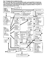
- the subject of the invention is also the equipment to perform the method mentioned, shown in Figure 1.
- This equipment consists of the units for separation and dewatering of sediments, conveyors of dewatered sediments, and combustion chamber with moving grate, and the essence of it lies in that the input part of the combustion chamber 9 of the boiler 17 for burning of the dried material consists of a set of distribution jets 5 for dosing of the fuel mixture 6 , situated above the front end of the moving grate 8 , and under the front end of the moving grate 8 is situated inlet 10 of hot air 7 with regulation fitting, the feed of the fuel mixture 6 is through the distributing jets 5 into a blast of hot air 7 above the front end of the moving grate 8 from the mixing equipment 4 with counter-rotating screws, which is fitted with the inlets 1.2 ...
- the combustion gases ducting 11 with a steam exchanger 12 and other boiler draughts 17 above the moving grate 8 is arranged the combustion gases ducting 11 with a steam exchanger 12 and other boiler draughts 17 ,the duct system 13 with flue exhauster and desulphurization equipment into the chimney and under the grate 8 is situated the outlet of ash 14 via a water seal 15 into the storage container 16.
- the combustion method is designed so that it is possible to burn loose or granulated dried material from the equipment for distillers' stillage processing.
- the dried material consists of separated distillers' stillage and sediments from anaerobic and aerobic parts of the equipment for processing of stillage, which are dried again to the required concentration of dried residue in a drier.
- the equipment is able to produce high-pressure or medium-pressure steam and / or hot water for technological needs of the distillery. It is equipped with the accessories enabling preparation of feed water, dosing of the fuel into the boiler, removal of ash and cinders, treatment of combustion gases and processing of the combustion gases treatment products so that these then may be deposited at a dumping site.
- Burning of the dried stillage and sediments results in reduced volumes of wastes that must be deposited at dumping sites, the treatment and desulphurization of combustion gases allow to reduce the amount of harmful substances released into the environment, by which means the adverse impacts of distillery operation on the environment are eliminated.
- the dried stillage is brought from storage container to the mixing and dosing equipment, which doses the fuel into the combustion chamber according to the requirements for the boiler output.
- Changing the quantity and the fuel composition is achieved by changing the speed of the shifting and revolution of the parts of the mixing and dosing equipment, which may consist of belt or screw conveyors.
- the dosing and mixing equipment also enables the partial drying of the fuel prior its entry into combustion chamber. Preparation and conveying of the fuel into boiler is shown schematically in Figure No. 1.
- the air required for combustion is drawn in from the area of boiler room through effective filters and is let in as primary, secondary and tertiary to appropriate places of the combustion chamber.
- the combustion chamber is divided into several zones, and the fuel moves through the combustion chamber individual zones on a moving grate, which is either a moving one or it is divided into several independent sections.
- the fuel on the grate is mixed with air that is simultaneously utilised for cooling of the grate.
- a water circuit may be used, too.
- the final zone is designed as a burn down one, where the un-burned volatile substances not released from the fuel in the preceding zones are burnt up.
- the spent fuel falls down from the combustion area at the grate end, it cools-down and is taken to the storage container, and from there it is transported to a dumping site.
- Combustion gases from combustion chamber flow through one or more draughts into a steam exchanger, where the water is brought to boil.
- Combustion gases run through the steam exchanger inside a piping system, while water is outside of the piping.
- the generated saturated steam is deprived of water droplets and conducted to a distributor and from there to the demand sites.
- an economizer - exchanger At the stream of combustion gases exit from the boiler is introduced an economizer - exchanger, in which the feed water is preheated before it enters the steam exchanger.
- the economizer cools the combustion gases and so increases the boiler efficiency.
- combustion gases pass through desulphurization equipment, where the sulphur oxides content is decreased to the required concentration.
- Desulphurization of combustion gases is carried out by a wet or dry process by dosing ground limestone or lime slurry into the stream of combustion gases.
- the formed gypsum is separated from combustion gases and collected in a container.
- the wet desulphurization process is used, the gypsum is dried to make the handling easier.
- Gypsum is deposited at dumping sites as stable product not containing any hazardous substances.
- Desulphurized combustion gases are diverted into the chimney and released into atmosphere.
- the dry desulphurization method is used, the products of reactions are trapped on a filter, which is inserted before the inlet into the chimney.
- Circulating condensate from the distillery technological process is collected in condensate header tank. Condensate is mixed with treated water from chemical treatment plant, which compensates for the losses of steam and condensate at demand sites and piping routes.
- the circulating condensate and topping-up water mixture is pumped over exchanger into de-aerator and into feed tank. Water is warmed up by steam before being de-aerated in de-aerator. The required chemicals are dosed into the de-aerated feed water, and the feed water is pumped through the economizer into the steam exchanger.
- the equipment is provided with its own control system that monitors the required operational parameters (temperatures, pressures, levels, through-flows, etc.) and controls supply of fuel and feed water, and steam output from the boiler.
- the boiler is fitted with all prescribed fixtures and elements that allow unattended operation. This allows limiting the presence of service personnel only to the times of the start-up and shutdown. Within the period of permanent steady operation, only the daily inspection rounds to check the operation of the boiler are required.
- Dried stillage or other components of fuel 101 are collected in containers of the fuel components 102.
- Fuel is made by mixing the components in the mixing and homogenizing member 103, which doses the fuel on grate 104 of the combustion chamber 105 according to the requirements for the current output of the boiler.
- Changing the fuel quantity and composition is achieved by changing the speed of the motion and revolutions of the parts of the mixing and dosing equipment 103 , which may consists of belt or screw conveyors.
- the mixing and dosing equipment 103 also enables partial drying of the fuel prior its entry into combustion chamber 105. Schematic diagram of preparation and entry of the fuel into the boiler is shown in Figure 1.
- the air required for combustion 129 is drawn in through effective filters 130 and dampers 131 and is conducted as primary, secondary and tertiary into appropriate places of the combustion chamber 105 .
- the combustion chamber 105 is divided into several zones, and the fuel moves through individual zones on a moving grate 104, which may be divided into several independent sections.
- the fuel on the grate 104 is mixed with the air 129, which is simultaneously utilised for cooling of the grate 104 .
- the fuel is burned gradually, including the volatile constituents.
- the spent fuel falls down from the combustion space at the end of the grate 104 into a water seal, cools down, and by means of the conveying device 114, it is carried into the container 146, from where it is transported to the dumping site.
- Combustion gases from combustion chamber flow through one or more of the steam exchanger 106.
- water is brought to boil and saturated steam 107 is produced.
- Combustion gases pass through the steam exchanger 106 inside piping system, while the water is outside the piping.
- the produced saturated steam 107 is deprived of water droplets and may be used directly as technological steam for the distillery technology. In that case, it is conducted directly into the medium-pressure steam distributor 119 and from there into technology 120 and through pressure limiting station 124 to the de-aerator and feed water tank 125 .
- the energy of combustion gases can also be used to produce high-pressure steam.
- saturated steam 107 is conducted to steam superheater 108 , where the required final temperature of high-pressure steam is reached.
- Superheated steam 109 is then conducted to the high-pressure steam distributor 115 and from there into a steam back-pressure turbine 116 .
- the steam turbine 116 drives the generator 117 , which produces electric power that may be used for the consumption of the distillery itself, or sold into public network as ecological electric power, as it has been generated by utilising the energy from biomass.
- the steam pressure drops to the level of medium-pressure steam suitable for the distillery's technological purposes.
- the medium-pressure steam distributor Prior to entry into the medium-pressure steam distributor, it is also necessary to reduce the steam temperature to the required value in the steam cooler 118 . The temperature reduction is achieved by feeding condensate 148 into steam blast. Further utilisation of steam is the same as in the case of production of saturated steam ( 107 ).
- the pressure limiting station 135 Between the high-pressure steam distributor 115 and the distributor of medium-pressure steam 119 is introduced the pressure limiting station 135 , which serves to lower the steam pressure in the cases of the steam turbine 116 being out of operation.
- combustion gases are drawn through duct system with flue exhauster 111 and conducted to chimney 113 .
- combustion gases pass through desulphurization equipment 112 , where the content of sulphur oxides is decreased to the required concentration.
- Desulphurization of combustion gases is done by wet or dry method by dosing ground limestone or lime slurry into ( 133 ) into a stream of combustion gases.
- the formed gypsum 134 is separated from combustion gases and collected in a container. When the wet desulphurization process is applied, gypsum 134 is dried to make the handling easier. Gypsum 134 is deposited at dumping sites as stable product that contains no hazardous substances. De-sulphurized combustion gases are diverted into the chimney 113 and released into atmosphere.
- Circulating condensate 121 from technological process of the distillery is collected in condensate header tank 122 .
- Condensate is mixed with treated water 149 from chemical water treatment plant 144 , which compensates the losses of steam and condensate at demand sites and piping routes with topping-up water 143 from the sources outside the boiler room.
- topping-up water 149 is warmed up in exchanger 141 .
- the mixture of circulating condensate 121 and treated topping-up water 149 is pumped over into de-aerator 125 and into a feed tank.
- water is warmed up with the steam from the limiting station 124 .
- the required chemicals are dosed into de-aerated feed water and the feed water is then pumped by the pump 126 through the economizer 110 into steam exchanger 106 .
- the boiler room accessories include a process expander 128 , which collects the condensates formed during operation of the boiler and steam turbine, and expanders of sludge 139 and continuous blow-down water 140, which serve to take the salts from the exchanger 106 into cooling trap 142 .
- part of accessories is the seal steam condenser 136 , in which takes place the condensation of the steam from seals of steam turbine 116 .
- the condenser of seal steam 136 is cooled by cooling water 137, 138 from external cooling circuit.
- the equipment for burning of stillage is equipped with its own control system which monitors and controls the boiler and steam turbine operation, solves operational and emergency conditions, and protects the equipment against damage.
Landscapes
- Chemical & Material Sciences (AREA)
- Engineering & Computer Science (AREA)
- Environmental & Geological Engineering (AREA)
- Organic Chemistry (AREA)
- Oil, Petroleum & Natural Gas (AREA)
- Water Supply & Treatment (AREA)
- Life Sciences & Earth Sciences (AREA)
- Chemical Kinetics & Catalysis (AREA)
- Hydrology & Water Resources (AREA)
- General Engineering & Computer Science (AREA)
- General Chemical & Material Sciences (AREA)
- Mechanical Engineering (AREA)
- General Life Sciences & Earth Sciences (AREA)
- Geochemistry & Mineralogy (AREA)
- Geology (AREA)
- Treatment Of Sludge (AREA)
- Solid Fuels And Fuel-Associated Substances (AREA)
Applications Claiming Priority (1)
| Application Number | Priority Date | Filing Date | Title |
|---|---|---|---|
| CZ20060617A CZ2006617A3 (cs) | 2006-09-29 | 2006-09-29 | Zpusob energetického zhodnocení produktu z cištení výpalku z výroby biolihu a zarízení k provádení tohoto zpusobu |
Publications (2)
| Publication Number | Publication Date |
|---|---|
| EP1955981A2 true EP1955981A2 (fr) | 2008-08-13 |
| EP1955981A3 EP1955981A3 (fr) | 2009-10-07 |
Family
ID=39262770
Family Applications (1)
| Application Number | Title | Priority Date | Filing Date |
|---|---|---|---|
| EP20070466019 Withdrawn EP1955981A3 (fr) | 2006-09-29 | 2007-09-14 | Procédé pour l'appréciation de l'énergie des produits issus de la purification de drêche de distillerie de la production d'éthanol et équipement pour la mise en oeuvre de ce procédé |
Country Status (3)
| Country | Link |
|---|---|
| EP (1) | EP1955981A3 (fr) |
| CZ (1) | CZ2006617A3 (fr) |
| RU (1) | RU2007133436A (fr) |
Cited By (3)
| Publication number | Priority date | Publication date | Assignee | Title |
|---|---|---|---|---|
| WO2012095556A1 (fr) * | 2011-01-14 | 2012-07-19 | Vapo Oy | Procédé d'utilisation de l'énergie thermique des gaz en produit dans une usine appartenant à la filière btl |
| CN105417777A (zh) * | 2015-12-01 | 2016-03-23 | 大连爱安沃特环境技术有限公司 | 污水混凝吸附沉淀分离—分离物厌氧沼气化再生处理方法 |
| CN105526591A (zh) * | 2015-12-10 | 2016-04-27 | 广东石油化工学院 | 一种糖蜜酒精废液的处理工艺 |
Family Cites Families (8)
| Publication number | Priority date | Publication date | Assignee | Title |
|---|---|---|---|---|
| GB436708A (en) * | 1935-02-27 | 1935-10-16 | Int Comb Ltd | Improvements in boiler furnaces |
| DE2329626C3 (de) * | 1973-06-09 | 1979-03-22 | Alb. Klein Kg, 5241 Niederfischbach | Verbrennungsofen, insbesondere für granuliertes Verbrennungsgut |
| US5250182A (en) * | 1992-07-13 | 1993-10-05 | Zenon Environmental Inc. | Membrane-based process for the recovery of lactic acid and glycerol from a "corn thin stillage" stream |
| US20030019736A1 (en) * | 2001-06-06 | 2003-01-30 | Garman Daniel T. | System and method for producing energy from distilled dry grains and solubles |
| WO2003025459A1 (fr) * | 2001-09-14 | 2003-03-27 | Fls Miljø A/S | Chaudiere et procede permettant d'extraire de l'energie d'un combustible |
| US7263934B2 (en) * | 2003-02-24 | 2007-09-04 | Harris Contracting Company | Methods for generating energy using agricultural biofuel |
| CA2536991C (fr) * | 2003-08-29 | 2009-03-24 | Ultraforce Technology Llc | Production d'alcool faisant appel a la sonication |
| US20060006116A1 (en) * | 2004-07-09 | 2006-01-12 | Scheimann David W | Method of dewatering thin stillage processing streams |
-
2006
- 2006-09-29 CZ CZ20060617A patent/CZ2006617A3/cs unknown
-
2007
- 2007-09-06 RU RU2007133436/13A patent/RU2007133436A/ru not_active Application Discontinuation
- 2007-09-14 EP EP20070466019 patent/EP1955981A3/fr not_active Withdrawn
Cited By (6)
| Publication number | Priority date | Publication date | Assignee | Title |
|---|---|---|---|---|
| WO2012095556A1 (fr) * | 2011-01-14 | 2012-07-19 | Vapo Oy | Procédé d'utilisation de l'énergie thermique des gaz en produit dans une usine appartenant à la filière btl |
| CN103380198A (zh) * | 2011-01-14 | 2013-10-30 | Vapo有限公司 | 用于利用生物质制油工厂中产生的气体的热能的方法 |
| CN105417777A (zh) * | 2015-12-01 | 2016-03-23 | 大连爱安沃特环境技术有限公司 | 污水混凝吸附沉淀分离—分离物厌氧沼气化再生处理方法 |
| CN105417777B (zh) * | 2015-12-01 | 2018-03-16 | 大连爱安沃特环境技术有限公司 | 污水混凝吸附沉淀分离—分离物厌氧沼气化再生处理方法 |
| CN105526591A (zh) * | 2015-12-10 | 2016-04-27 | 广东石油化工学院 | 一种糖蜜酒精废液的处理工艺 |
| CN105526591B (zh) * | 2015-12-10 | 2018-08-14 | 广东石油化工学院 | 一种糖蜜酒精废液的处理工艺 |
Also Published As
| Publication number | Publication date |
|---|---|
| RU2007133436A (ru) | 2009-03-20 |
| EP1955981A3 (fr) | 2009-10-07 |
| CZ2006617A3 (cs) | 2008-04-09 |
Similar Documents
| Publication | Publication Date | Title |
|---|---|---|
| US4100730A (en) | Regulation of a wet air oxidation unit for production of useful energy | |
| US8409303B2 (en) | Slurry dewatering and conversion of biosolids to a renewable fuel | |
| JP7790650B2 (ja) | 消化液処理水と有機物乾燥物質の混合液を用いてバイオガスを生産するシステム | |
| Peltola et al. | A novel dual circulating fluidized bed technology for thermal treatment of municipal sewage sludge with recovery of nutrients and energy | |
| US20170275195A1 (en) | Method and arrangement for wastewater treatment | |
| TWI822008B (zh) | 氫製造系統 | |
| EP3945077B1 (fr) | Processus et système de traitement de biosolides | |
| JP4081102B2 (ja) | 廃棄物複合処理施設 | |
| EP1955981A2 (fr) | Procédé pour l'appréciation de l'énergie des produits issus de la purification de drêche de distillerie de la production d'éthanol et équipement pour la mise en oeuvre de ce procédé | |
| CN103524008A (zh) | 一种城镇污水厂污泥零排放自动化处理处置工艺 | |
| ITCR20100004A1 (it) | Impianto per il trattamento di fanghi biologici con recupero di materie prime seconde ed energia | |
| ES2926949T3 (es) | Carbonización hidrotérmica | |
| CN111268888B (zh) | 一种用于市政污泥的处置工艺及其处置系统 | |
| JP7628577B2 (ja) | 二酸化炭素吸収剤、二酸化炭素吸収設備、二酸化炭素吸収方法及び二酸化炭素吸収剤の製造方法 | |
| JP2010149079A (ja) | 高含水廃棄物を含んだ廃棄物の処理方法および処理装置 | |
| WO2020008621A1 (fr) | Méthode de production d'hydrogène à l'aide de biomasse en tant que matière première | |
| KR101872428B1 (ko) | 간접가열식 건조공정으로 이루어지는 하수슬러지 처리 시스템 | |
| KR101113253B1 (ko) | 유기폐기물을 이용한 바이오가스 생산 시스템 | |
| CN218936357U (zh) | 一种生活垃圾焚烧协同污泥干化焚烧的系统 | |
| KR20170066801A (ko) | 분체 연소 장치를 이용한 슬러지 연료탄 제조 장치 | |
| CN202494119U (zh) | 一种城市污泥处理装置 | |
| Peltola et al. | An advanced process for thermal treatment of municipal sewage sludge | |
| Goss | Alternate: Do I Need to Dry The Cake? An Overview of Sludge Drying Technologies and Drivers for Implementation in the Carolinas | |
| Botta et al. | Energy and Material Recovery from Municipal Sludge | |
| Guibelin | Sustainability of thermal oxidation processes: strengths for the new millennium |
Legal Events
| Date | Code | Title | Description |
|---|---|---|---|
| PUAI | Public reference made under article 153(3) epc to a published international application that has entered the european phase |
Free format text: ORIGINAL CODE: 0009012 |
|
| AK | Designated contracting states |
Kind code of ref document: A2 Designated state(s): AT BE BG CH CY CZ DE DK EE ES FI FR GB GR HU IE IS IT LI LT LU LV MC MT NL PL PT RO SE SI SK TR |
|
| AX | Request for extension of the european patent |
Extension state: AL BA HR MK RS |
|
| PUAL | Search report despatched |
Free format text: ORIGINAL CODE: 0009013 |
|
| AK | Designated contracting states |
Kind code of ref document: A3 Designated state(s): AT BE BG CH CY CZ DE DK EE ES FI FR GB GR HU IE IS IT LI LT LU LV MC MT NL PL PT RO SE SI SK TR |
|
| AX | Request for extension of the european patent |
Extension state: AL BA HR MK RS |
|
| RIC1 | Information provided on ipc code assigned before grant |
Ipc: C02F 103/32 20060101ALN20080624BHEP Ipc: C02F 103/26 20060101ALN20080624BHEP Ipc: C02F 11/06 20060101ALI20090828BHEP Ipc: F23G 7/02 20060101AFI20090828BHEP |
|
| AKX | Designation fees paid |
Designated state(s): AT BE BG CH CY CZ DE DK EE ES FI FR GB GR HU IE IS IT LI LT LU LV MC MT NL PL PT RO SE SI SK TR |
|
| STAA | Information on the status of an ep patent application or granted ep patent |
Free format text: STATUS: THE APPLICATION IS DEEMED TO BE WITHDRAWN |
|
| 18D | Application deemed to be withdrawn |
Effective date: 20100408 |