EP1956143A2 - Système d'habillage pour un rail, en particulier rail de tramway - Google Patents
Système d'habillage pour un rail, en particulier rail de tramway Download PDFInfo
- Publication number
- EP1956143A2 EP1956143A2 EP08001239A EP08001239A EP1956143A2 EP 1956143 A2 EP1956143 A2 EP 1956143A2 EP 08001239 A EP08001239 A EP 08001239A EP 08001239 A EP08001239 A EP 08001239A EP 1956143 A2 EP1956143 A2 EP 1956143A2
- Authority
- EP
- European Patent Office
- Prior art keywords
- rail
- covering system
- intermediate layer
- head
- kammerfüllelement
- Prior art date
- Legal status (The legal status is an assumption and is not a legal conclusion. Google has not performed a legal analysis and makes no representation as to the accuracy of the status listed.)
- Granted
Links
- 239000011248 coating agent Substances 0.000 title description 3
- 238000000576 coating method Methods 0.000 title description 3
- 239000000463 material Substances 0.000 claims description 98
- 239000010410 layer Substances 0.000 claims description 65
- 230000009969 flowable effect Effects 0.000 claims description 13
- 229920001971 elastomer Polymers 0.000 claims description 9
- 230000015572 biosynthetic process Effects 0.000 claims description 7
- 239000011229 interlayer Substances 0.000 claims description 6
- 239000008187 granular material Substances 0.000 claims description 5
- 238000010438 heat treatment Methods 0.000 claims description 4
- 238000001816 cooling Methods 0.000 claims description 3
- 238000004064 recycling Methods 0.000 claims description 3
- 239000012815 thermoplastic material Substances 0.000 claims description 3
- 239000006261 foam material Substances 0.000 claims description 2
- 239000004566 building material Substances 0.000 claims 1
- 239000000945 filler Substances 0.000 claims 1
- 239000000853 adhesive Substances 0.000 description 13
- 230000001070 adhesive effect Effects 0.000 description 13
- 239000010426 asphalt Substances 0.000 description 9
- 230000006835 compression Effects 0.000 description 9
- 238000007906 compression Methods 0.000 description 9
- 238000010276 construction Methods 0.000 description 7
- 238000005253 cladding Methods 0.000 description 6
- 239000007787 solid Substances 0.000 description 6
- 239000004814 polyurethane Substances 0.000 description 5
- 229920002635 polyurethane Polymers 0.000 description 5
- 239000007788 liquid Substances 0.000 description 4
- 238000012423 maintenance Methods 0.000 description 4
- 230000000712 assembly Effects 0.000 description 3
- 238000000429 assembly Methods 0.000 description 3
- 230000008901 benefit Effects 0.000 description 3
- 238000013461 design Methods 0.000 description 3
- 238000009413 insulation Methods 0.000 description 3
- 230000035515 penetration Effects 0.000 description 3
- 239000004033 plastic Substances 0.000 description 3
- 229920003023 plastic Polymers 0.000 description 3
- 238000003466 welding Methods 0.000 description 3
- 230000001680 brushing effect Effects 0.000 description 2
- 239000002131 composite material Substances 0.000 description 2
- 230000008878 coupling Effects 0.000 description 2
- 238000010168 coupling process Methods 0.000 description 2
- 238000005859 coupling reaction Methods 0.000 description 2
- 230000000694 effects Effects 0.000 description 2
- 238000004519 manufacturing process Methods 0.000 description 2
- 230000005855 radiation Effects 0.000 description 2
- 230000009467 reduction Effects 0.000 description 2
- 230000007704 transition Effects 0.000 description 2
- 244000025254 Cannabis sativa Species 0.000 description 1
- 239000004831 Hot glue Substances 0.000 description 1
- 230000001413 cellular effect Effects 0.000 description 1
- 150000001875 compounds Chemical class 0.000 description 1
- 239000004020 conductor Substances 0.000 description 1
- 239000004035 construction material Substances 0.000 description 1
- 239000000109 continuous material Substances 0.000 description 1
- 238000013016 damping Methods 0.000 description 1
- 238000011161 development Methods 0.000 description 1
- 238000006073 displacement reaction Methods 0.000 description 1
- 229920001821 foam rubber Polymers 0.000 description 1
- 239000003292 glue Substances 0.000 description 1
- 239000012943 hotmelt Substances 0.000 description 1
- 238000009434 installation Methods 0.000 description 1
- 230000010354 integration Effects 0.000 description 1
- 230000003993 interaction Effects 0.000 description 1
- 239000002184 metal Substances 0.000 description 1
- 238000000034 method Methods 0.000 description 1
- 230000000737 periodic effect Effects 0.000 description 1
- 239000005077 polysulfide Substances 0.000 description 1
- 229920001021 polysulfide Polymers 0.000 description 1
- 150000008117 polysulfides Polymers 0.000 description 1
- 239000011148 porous material Substances 0.000 description 1
- 230000008569 process Effects 0.000 description 1
- 238000012545 processing Methods 0.000 description 1
- 230000000284 resting effect Effects 0.000 description 1
- 239000003566 sealing material Substances 0.000 description 1
- 238000009751 slip forming Methods 0.000 description 1
- 239000002689 soil Substances 0.000 description 1
- 125000006850 spacer group Chemical group 0.000 description 1
- 238000005507 spraying Methods 0.000 description 1
- 239000000758 substrate Substances 0.000 description 1
Images


Classifications
-
- E—FIXED CONSTRUCTIONS
- E01—CONSTRUCTION OF ROADS, RAILWAYS, OR BRIDGES
- E01B—PERMANENT WAY; PERMANENT-WAY TOOLS; MACHINES FOR MAKING RAILWAYS OF ALL KINDS
- E01B19/00—Protection of permanent way against development of dust or against the effect of wind, sun, frost, or corrosion; Means to reduce development of noise
- E01B19/003—Means for reducing the development or propagation of noise
-
- E—FIXED CONSTRUCTIONS
- E01—CONSTRUCTION OF ROADS, RAILWAYS, OR BRIDGES
- E01B—PERMANENT WAY; PERMANENT-WAY TOOLS; MACHINES FOR MAKING RAILWAYS OF ALL KINDS
- E01B21/00—Track superstructure adapted for tramways in paved streets
Definitions
- the present invention relates to a rail covering system for a rail.
- a rail has a rail head, a rail foot and a rail web connecting the rail head to the rail foot.
- Cladding systems for such rails are generally used in the field of tram track systems in which the top of the rail head is nearly level with a track area adjacent to a rail or any other material surrounding the rails, such as a rail track. also soil with grass grown on it, ends.
- the present invention particularly, but not exclusively, relates to such rail covering systems as used in tramway rails.
- an inventive rail covering system in the area of other rails, such as those used for train track systems or in cranes on a factory site.
- a rail track which is coated with poorly conductive materials.
- This enclosure comprises on both sides of a respective rail arranged Kammer Hällense that extend from the rail foot region to the rail head portion in the vertical direction and engage with an engagement portion in each formed between the rail head and the rail foot rail chamber.
- the rails are rigidly mounted on a substrate such as sleepers. Between the rails and the Kammer Strukturllelelementen compliant, soft insulating layers are arranged.
- a rail covering system for a rail in particular tram rail, which rail comprises a rail head, a rail foot and a rail web connecting the rail head to the rail foot, wherein the system has an elastic support to be positioned under the rail foot and allowing a vertical movement of the rail comprises, at least one Kammerirrillelement which is to be positioned at least partially engaging in a chamber formed between the rail head and the rail, an elastic intermediate layer over which at least one Kammer hypollelement on the rail is iststüzt such that the rail under deformation of the elastic support successful vertical movement under deformation of the intermediate layer with respect to the at least one Kammer hypollelelements is vertically movable.
- an elastic intermediate layer is inserted between the rail positioned on an elastic support and a chamber filling element adjacent thereto.
- This elastic intermediate layer allows a relative movement between the rail and the Kammer Strukturllelelement in the vertical direction under compression of this elastic intermediate layer.
- a vibration-related decoupling of the chamber filling element from the rail is achieved.
- the rail In the case of impacts that are generated by a train when driving over such a rail, the rail can be under compression move the support vertically, without that also the Kammer spallelement must be moved vertically. This means that the total mass of the oscillating or moving system can be reduced to the mass of the rail itself. This allows under the given forces much faster evasive movements of the rail and thus leads to a significantly better damping comfort. Also, a significantly better noise reduction can be achieved by this decoupling of the rail of the Kammer hypollmaschinen.
- the rail will essentially move vertically on its own, a relative movement will occur between the rail and the chamber filling element, while the chamber filling element will remain substantially unchanged from the adjacent superstructure.
- the demarcation of the Kammerdrallelements to the superstructure is then significantly relieved due to the no longer existing relative movement. This is advantageous because, due to the materials used for the superstructure, it is often more difficult to produce a firm adhesive bond there, especially when a permanent up and down movement leads to a heavy load.
- the intermediate layer be provided with such a material thickness that it can be compressed in the vertical direction at least to an extent is, in which the elastic support allows a vertical movement of the rail.
- a decoupling of the movement of the Kammer hypollelements of the movement of the thus provided in the composite rail can already be achieved in an advantageous development in that the elastic intermediate layer has an elasticity, the greater is, as the elasticity of the elastic intermediate layer to be supported on the rail at least one Kammer hypollelements.
- the elasticity of the elastic intermediate layer corresponds at least to the elasticity of the elastic support.
- the elastic intermediate layer supports the at least one chamber filling element at least on an upper side of the rail foot and a lower side of the rail head.
- the elastic intermediate layer to support the at least one chamber filling element on the rail web. This is particularly advantageous for optimizing the sound insulation between the rail and the chamber filling element.
- the elastic interlayer may be provided, at least in part, by closed cell foam material, e.g. Rubber foam.
- closed cell foam material e.g. Rubber foam.
- the elastic intermediate layer is fixed to one of the rail facing to be positioned side of the at least one Kammer hypollelements.
- the elastic intermediate layer is to be placed as a separate assembly between the at least one Kammer hypollelement and the rail.
- the elastic intermediate layer is provided at least in part by introducing a flowable, hardenable interlayer material into a gap formed between the rail and the at least one chamber filling element.
- a gap is created between a chamber filling element during assembly and the rail is left and this gap then filled with the flowable and hardenable interlayer material. This ensures that even smaller gaps can be reliably and completely filled with such material.
- the movement decoupling of a chamber filling element from a rail during vertical compression movement of the same can be further assisted by the fact that the at least one chamber filling element can be locked by a locking arrangement against vertical movement with the rail.
- the present invention further relates to a Schienenum modeugssystem for a rail, in particular tram track, which comprises a rail head, a rail foot and the rail head with the rail connecting rail web, further comprising at least one Kammer hypollelement which at least partially into a chamber formed between the rail head and the rail engaging, wherein the at least one Kammer Stahlllelement comprises a lower part which is to be positioned with an engaging portion engaging into the chamber, and an upper part which is to be positioned on the lower part so that it is adjacent to the rail head and provides an upwardly exposed surface of the at least one Kammer hypollelements.
- Such maintenance includes, for example, brushing the tread formed at the top of the rail head with rotating brushes. Damage to the material adjacent to the rail head portion of a cladding system by such a brush or damage to the brush by this material, especially if this is formed by bitumen material or the like, can thus be avoided. There is also no risk of damage to the near-surface areas during welding work on the rails.
- a part of the upper part and the lower part have a connection projection formation, which for connection with the other part of the upper part and lower part in a connection recess formation of the other Partially engaging to position.
- the at least one chamber filling element can be constructed with rubber granulate material. This can be obtained, for example, in a recycling process by the processing of the treads of vehicle tires. When producing a chamber filling element, this granulate can then be glued or baked on its surface with polyurethane adhesive or other adhesive material which cures or vulcanizes when heated and subjected to pressure.
- the upper part and the lower part may be substantially be constructed with the same construction material. Furthermore, it can be provided that the upper part and / or the lower part is constructed in its near-surface volume region with Neugummimaterial. Such new rubber material then forms a very uniform surface, generally not interrupted by any pores or inclusions, with high quality and weather and radiation resistance.
- the at least one Kammer spallelement in its position to be positioned next to the rail head has a recess formation for receiving a material connection between the rail head and the at least a Kammer mitllelement producing connecting material.
- the bonding material can penetrate into the recess formation. On the one hand, this leads to an increased adhesion surface and, on the other hand, after curing of the bonding material, to a connection which is positive in the vertical direction between this material and the chamber filling element, so that the adhesive bond is relieved.
- the bonding material can provide the interlayer material.
- the present invention further relates to a rail system comprising a rail, in particular tram rail, with a rail head, a rail and a rail connecting the rail head with the rail foot, further comprising a rail enclosing and inventively constructed rail cover system.
- the connecting material may be thermoplastic material which can be brought into a flowable mounting state by heating and can be brought into its elastic connection state by cooling, in which it adheres to the components to be joined or their surfaces, but is elastically deformable in its volume region.
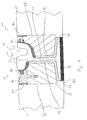
- the Fig. 1 1 shows a section of a tram track system 10 with a rail 12 and a rail covering system 14 explained in detail below.
- the superstructure 16, 18, which can be constructed, for example, with asphalt material or concrete material and also for other vehicles, is located on either side of the rail 12 or the rail covering system 14. such as automobiles, provides drivable surface 20.
- the rail 12 and the superstructure 16, 18 lie on a solid surface, not shown, such as a concrete slab on which the rail is fixed to suitable positioning by screwing or the like.
- the rail 12 is constructed in a conventional manner and has a rail head 22 with a groove 24 formed therein for the wheel rim of a tram wheel.
- a rail web 26 which connects the rail head 22 with a rail 28.
- chambers 30, 32 are formed between the rail head 22 and the rail foot.
- the rail head 22 is positioned with respect to the surface 20 provided by the superstructure 16, 18 so that a rail running surface 34, which is also run with a rail wheel, lies approximately at the same level in vertical direction as the surface 20.
- vertical direction in the context of the present invention is generally understood to mean a direction which is the one in Fig. 1 drawn with dashed line center line L of the rail 12 corresponds. In inclined installation of such a rail 12, for example in an excessive curve area, this height center line L, so also the vertical direction, of course, deviate from a geometric vertical.
- the railing system 14 includes on both sides of the rail 12 a plurality of in a plane of the drawing Fig. 1 orthogonal stationary rail longitudinal direction successive Kammer hypoll instituten 36, 38 on the rail outside and on the rail inside.
- Each of the chamber filling elements 36, 38 is designed such that it engages with an engagement region 40 or 42 in the respective chamber 30 or 32 between the rail head 22 and the rail foot 28.
- At their side facing away from the rail 12 each sides form the Kammer Stahlllmaschine 36, 38 approximately vertically and rectilinearly extending surfaces 44, 46, to which also the material of the superstructure 16 and 18 adjacent.
- successive Kammer hypoxia are formed in two parts with a lower part 48, which also provides the engagement portion 40 substantially, and an upper part 50, which on the lower part 48th is positioned resting and next to the surface 20 of the superstructure 16 and the rail running surface 34 an upwardly exposed surface 52 of this positioned on the rail outside Kammer spallelements 36 provides.
- the chamber filling element 38 positioned on the inside of the rail is designed in one piece and provides both the engagement region 42 and the upwardly exposed surface 54, which can be approximately at the same height level as the adjacent surfaces of the rail head 22 and the superstructure 18, respectively ,
- a connection between the lower part 58 and the upper part 50 can be generated in the manner of a tongue and groove connection.
- the lower chamber filling element 48 has a groove 54 which preferably passes through in the longitudinal direction of the rail and into which a spring 56, which is preferably formed continuously on the lower side of the upper part 50, is inserted, for example under press fit.
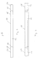
- FIGS. 2 and 3 show such upper parts 50 of the Kammer hypollelements 36 in plan view and in side view. It can be seen that in their adjoining end regions 58 and 60, the upper parts 50 are also designed so that they engage in one another.
- the dimensioning of these upper parts 50 is preferably such that they have approximately the same extent in the vertical direction, ie in the vertical direction, as the region of the rail head 22 adjacent thereto Fig. 1 in that in fact the upper parts 50 here have a slightly greater vertical extent.
- these upper parts 50 are preferably designed such that they extend over a plurality of lower parts 48.
- the upper parts 50 may have a length of 3 m to 4 m. This means that one and the same upper part 50 may be associated with a plurality of lower parts 48 for completing a respective Kammer hypollelements 36. It should also be pointed out that preferably the upper parts 50 are laid in such a way that their adjoining end regions 58, 60 are not located where end regions of lower parts 48 which follow one another directly in the longitudinal direction of the rail are also located.
- the Kammer spalletti 36, 38, ie in the Kammer spallelement 36 and the lower part 48 and the upper part 50 may for example be constructed by recycling Altgummigranulat that under heat and pressure load and use of the granules surfaces coating adhesive material, such as polyurethane or the like, is baked and is brought by using appropriate forms in the desired shape. It can be provided that the near-surface areas is not provided by recycled granular material, but by mat-like in the respective form inserted new rubber material which is vulcanized in the manufacture of the Kammer circallmaschine 36, 38 for the first Man. This generates a high-quality surface, in which the risk of penetration of moisture or liquid is largely excluded and which has a good resistance to weathering and UV radiation.
- the Kammer hypothalamic valve 36, 38 Since the largest volume fraction of the Kammer hypollemia 36, 38 can be constructed of very inexpensive recycled material, the Kammer hypollemia 36, 38 can be generally produced in a cost effective manner. In particular, in the case of such a production, they can also already be produced with the desired shape, ie in the case of the chamber filling element 36, the grooves 54 or springs 56 can also be mitangeformt to the respective parts 48, 50.
- the chamber filling elements 36, 38 are practically not in direct contact with the rail 12 at any point.
- the rail web 26 and the underside of the rail head 22 between the Kammer hypollensen 36, 38 and the rail 12 each have an elastic intermediate layer 62, 64 is provided.
- This elastic intermediate layer is constructed of material which has a greater elasticity, ie a greater modulus of elasticity, than the material of the Kammer hypollemia 36, 38. So these are in construction of rubber material, especially Altgummigranulat, equipped with a certain elasticity, but are for the In the case of such cladding systems, forces should be regarded essentially as rigid bodies.
- the elastic intermediate layers 62, 64 are constructed with a material having an elasticity which is at least as great as the elasticity of the material used for an elastic support 66.
- This elastic support 66 lies between the solid base and the rail foot 28, so that due to the elasticity or compressibility of the elastic support 66 under load, so for example when driving over a train, the rail 12 is vertical, ie in the direction of its longitudinal center line L, can move. The extent of this movement is essentially determined by the elasticity of the elastic support 66 on the one hand and the thickness of this elastic support 66 on the other hand. In general, it can be assumed that these are elastic Support 66 allows a vertical movement of the rail L in the range of about 1.5 mm. It should be noted here that, of course, the elastic support 66 may be formed as in the longitudinal direction of the rail under the rail 28 continuously continuous material layer.
- the intermediate layers 62, 64 are dimensioned with respect to their thickness that they allow under consideration of this elasticity occurring under their compression relative movement of the Kammer hypollemia 36, 38 with respect to the rail 12, which corresponds to the possible relative movement of the rail 12 under compression of the support 36.
- locking elements 68, 70th be provided, which may be constructed of rigid material, such as metal or hard plastic, and may be partially embedded in the material of the superstructure 16 and 18, for example.
- these locking elements 68, 70 are the Kammerhellemia 36, 38, so that even a greater vertical load can not lead to an evasive movement of the same down.
- the liners 62, 64 are not only provided where needed to provide motion decoupling, but also extend vertically along the rail web 26, thus forming substantially complete cladding for the rail 12 on both sides.
- the above-mentioned effect of motion decoupling thus also a significantly improved sound insulation behavior is achieved in the transition of sound from the rail 12 in the rail covering system 14.
- the intermediate layers 62, 64 may be constructed of closed-cell cellular rubber, such as foamed rubber material or foamed polyurethane.
- the intermediate layers 62, 64 can furthermore preferably be molded or vulcanized directly onto the chamber filling elements 36, 38 so that respective composite components are generated from the chamber filling element 36 or 38 and the intermediate layer 62 or 64.
- This simplifies the construction since with such intermediate layer material coated Kammer Glallmaschine 36, 38 can be easily delivered to a construction site and then positioned in conjunction with the intermediate layers adjacent to the rails or in the chambers 30, 32 can be pressed.
- the positioning preferably such that no cavities leading to the formation of resonances remain between the rail 12 and the intermediate layers 62, 64.
- it can also come to cavities between the intermediate layers 62 and 64 and the rail 12, taking into account certain structural conditions.
- intermediate layers 62, 64 as separate insert components and to position them either engaging in the chambers 30, 32 before inserting the chamber filling elements 36, 38, or initially a connection between the prefabricated intermediate layers 62, 64 and the Chamber filling elements 36, 38 produce and then laterally connected components adjacent to the rail 12 to position these components.
- the chamber filling elements 36, 38 are materially connected to the superstructure 16, 18 or the rail head 22 using an adhesive-like connecting material.
- this connection is substantially exclusively in the region of the upper part 50.
- connection material 72, 74 Adjacent to the superstructure 16 and 18 here connection material 72, 74 are used, which is constructed essentially with bitumen, but alternatively also with polysulfide, polyurethane or plastic adhesive. Above all, the use of bitumen is a cost-effective variant, which is advantageous due to the high elasticity of the bitumen material. Since a vertical movement between the Kammer circulllmaschinen 36, 38 and the superstructure 16, 18 substantially will not occur in the rail covering system 14 according to the invention, it can not be a shear stress here or overloading of the connecting material 72, 74 come.
- the connecting material 72 preferably covers the entire side surface of the upper part 50 facing the superstructure 16 and provides a connection to the superstructure 16 there.
- the upper part 50 may be formed with a side surface 76 which is set back relative to the lateral surface 44 of the lower part 48 of the Kammer Stahlllelements 36 in the direction of the rail 12 in order to provide sufficient volume for the connecting material 72 here.
- the upper region may be provided with side surface 78 set back relative to the surface 46, in order to thus provide a volume region in which the connecting material 74 can be received.
- a bonding material 80, 82 for the firm connection between the Kammer hypollensen 36, 38 and the rail head 22 is preferably used so-called "hot melt” material, ie hot melt adhesive material, which is made to flow by heating and solidified after cooling in a glue joint producing Condition is, however, is still elastic.
- This material is filled after heating in the intermediate chamber formed between the Kammer divellelement 36 and the upper part 50 thereof and the rail head 22. Also, between the upper part of the Kammer spallelements 38 and the rail head 22, the liquefied compound material 82 is filled in a corresponding space.
- the flowable bonding material 80 or 82 will move in the gaps and down until it passes through the upper edge region of the intermediate layers 62, 64 is prevented from further movement down.
- the gaps are completely filled upwards.
- the connection materials 80, 82 provide a stable connection between the chamber filling elements 36, 38 in their generated above the upper regions and the rail head 22, so that also here the penetration of liquid is prevented. Due to the elasticity of the connecting materials 80, 82, they can follow the movement of the rail head 22 vertically downward under shear deformation, or receive this movement, without the chamber filling elements 36, 38 simultaneously moving downwards.
- Another essential aspect is the design of the chamber filling element 36 provided on the outside of the rail with a lower part 48 and an upper part 50. This makes it possible to remove the upper part 50 from a track system 10 independently of the lower part 48, if this is required.
- a clearance can be created so that an unwanted interaction of a brush with there existing material can be avoided .
- bitumen material is damaged by the high temperatures during welding.
- the intermediate space next to the rail head 22 can be filled again with the upper parts 50, whereupon again the materials 72 and 80 can be filled in order to support the stable connection of the upper part 50.
- the thickness of the intermediate layers 62, 64 may vary along the surface of the rail 12, if necessary.
- the shape of the Kammer hypollense 36, 38 executed in a different way.
- the recesses 84, 86 in the respective upper region of the Kammer glycoll comprise 36, 38 may have other shapes or could be provided with a different number.
- a rib-like structure on the rail head 22 facing surface of the Kammer glycoll comprise 36, 38 could generate the desired effect.
- the intermediate layers 62, 64 also by coating the lateral surfaces of the rail 12, for example by spraying appropriate material, which can then harden to produce.
- suitable materials can be used both for the intermediate layers 62, 64 and for the support 66 for the loads occurring or the compressibilities required.
- foamed rubber material, but also foamed polyurethane or generally foamed thermoplastic material can be used, wherein these materials are preferably constructed closed cell, but of course can also be used in open-cell variation.
- the grooves or intermediate spaces formed in the end regions 58, 60 between the upper parts 50 between two successive chamber filling elements in the rail longitudinal direction can also be filled with a material which prevents the ingress of liquid.
- material 80 or 82nd can be used, with which a firm connection to the rail head 22 is obtained.
- FIG Fig. 4 An alternative embodiment of a track system or a rail covering system 14 provided thereon is shown in FIG Fig. 4 shown.
- Components or assemblies which correspond to components or assemblies described above in terms of construction or function are designated by the same reference numerals. Since the in Fig. 4 shown embodiment largely consistent with the above described, will be discussed below only the existing differences.
- the connecting material 80 not only extends to the side surface of the rail head 22 to make a material-fit connection with the upper part 50 of the Kammer Stahlllelements 36, but extends below the rail head 22 in that area in which on the rail outside of the rail head 22 merges into the rail web 26.
- the bonding material 80 terminates at the upper end surface of the intermediate layer 62, which then extends downwardly along the rail web 26 and the rail foot 28.
- the connecting material 82 is drawn on the inside of the rail head 22 to below the rail head 22 and ends where on the rail inside the rail head 22 merges into the rail web 26.
- This area is slightly lower than the area in which the rail head 22 merges into the rail web 26 on the outside of the rail.
- the connecting materials 80, 82 with comparatively high Elasticity are formed, so an elasticity that is higher than the elasticity of the Kammer hypollemia 36, 38, it is also possible in this embodiment that the rail 12 moves in the vertical direction without simultaneously a corresponding movement of the Kammer hypollemia 36, 38 to force.
- the elastic intermediate layer is provided here, at least in the upper region, by that region of the connecting materials 80, 82 which extends below the rail head 22 and is thus compressed during a downward movement of the rail 12.
- the provision of at least part of the intermediate layers 62, 64 of material initially introduced in flowable form and then hardening has the advantage that it becomes possible to reliably fill even smaller interstices or cavities, so that no cavities between the chamber filling elements 36, 38 and the rail 12 remain. This is particularly advantageous for reasons of better sound insulation.
- FIG Fig. 5 Another embodiment of a rail covering system 14 is shown in FIG Fig. 5 shown. This corresponds in terms of its essential structure of the variants described above, in particular with reference to the Fig. 1 to 3 described variant, so that essentially also on the comments on the Fig. 1 to 3 can be referenced.
- a substantially U-shaped rail foot covering element 94 is provided. This lies with a plate-like bottom portion 96 under the rail foot 28 and also under the elastic support 66 and overlaps the side of the elastic support 66 and the rail 28 with respective hook-like overgrip sections 98, 100.
- the Schienenfußummantelungselement 94 rests on the prepared solid ground and provides by its elastic support 66 and rail 98, 100 embracing arrangement provides protection for the elastic support 66 against both mechanical damage and moisture.
- the rail foot covering element 94 can be configured, for example, of plastic with comparatively little elasticity, so that, when the rail 12 is loaded from above, this rail foot covering element 94, in particular in its bottom region 96, is essentially not compressed.
- FIG. 5 Another aspect of in Fig. 5 shown embodiment is that the or at least one of the Kammer hypollemia 36, 38 in the respective engagement region 40 and 42 each have a recess, of which in Fig. 5 the recess 102 in the chamber filling element 36 can be seen.
- This recess 102 extends completely continuously in the rail longitudinal direction and thus increases the elasticity of the chamber filling element 36 in its region engaging in the associated chamber 30.
- the elastic intermediate layer 62 is interrupted, in particular in an embodiment in which the elastic intermediate layer 62 is fixedly or materially attached to the Kammer hypollelement 36.
- a recess 102 provides the advantage that in particular in rails used for tram rails 12 adjacent rails of the track system connecting transverse struts of the tie rods 104 can be screwed to the respective rail 26 foot.
- the bolts and nuts used for screwing are then in the range of these recesses 102, of which, of course, provided on the inside of the rail provided on the chamber filling element 38 also in the rail longitudinal direction recess can be provided.
- a lateral opening 106 may be provided, which is open to the recess.
- the elastic intermediate layers 62 and 64 are also possible, when providing such recesses, to provide the elastic intermediate layers 62 and 64, respectively, as components which are fundamentally separate from the respective chamber filling element 36 and 38, for example where the screw bolts form a connection between a strut 104 and a rail web 26, recesses can have.
- material-fit or solid connection of the elastic intermediate layers 62 and 64 with the respectively associated Kammer hypollelement 36, 38 these are then preferably divided into two areas, namely the respectively above or below the recess lying areas.
- the rail covering system according to the invention can be provided in any type of rail, that is, regardless of whether this is used for example as a so-called grooved rail for use in conjunction with a tram track system, or in a conventional Vingulschiene for normal can be used by trains accessible track systems.
Landscapes
- Engineering & Computer Science (AREA)
- Architecture (AREA)
- Civil Engineering (AREA)
- Structural Engineering (AREA)
- Railway Tracks (AREA)
- Road Paving Structures (AREA)
- Vehicle Step Arrangements And Article Storage (AREA)
- Branching, Merging, And Special Transfer Between Conveyors (AREA)
- Bridges Or Land Bridges (AREA)
- Framework For Endless Conveyors (AREA)
Applications Claiming Priority (1)
| Application Number | Priority Date | Filing Date | Title |
|---|---|---|---|
| DE102007006544A DE102007006544A1 (de) | 2007-02-09 | 2007-02-09 | Schienenumkleidungssystem für eine Schiene, insbesondere Straßenbahnschiene |
Publications (3)
| Publication Number | Publication Date |
|---|---|
| EP1956143A2 true EP1956143A2 (fr) | 2008-08-13 |
| EP1956143A3 EP1956143A3 (fr) | 2009-04-01 |
| EP1956143B1 EP1956143B1 (fr) | 2012-04-11 |
Family
ID=39327163
Family Applications (1)
| Application Number | Title | Priority Date | Filing Date |
|---|---|---|---|
| EP08001239A Not-in-force EP1956143B1 (fr) | 2007-02-09 | 2008-01-23 | Système d'habillage pour un rail, en particulier rail de tramway |
Country Status (3)
| Country | Link |
|---|---|
| EP (1) | EP1956143B1 (fr) |
| AT (1) | ATE553261T1 (fr) |
| DE (1) | DE102007006544A1 (fr) |
Cited By (7)
| Publication number | Priority date | Publication date | Assignee | Title |
|---|---|---|---|---|
| FR2947285A1 (fr) * | 2009-06-29 | 2010-12-31 | Plastiform S | Procede et dispositif pour realiser une etancheite le long d'un rail enterre. |
| EP2354300A1 (fr) * | 2010-02-03 | 2011-08-10 | Composite Damping Material N.V. In Het Kort "Cdm" | Système à rail imbriqué |
| WO2012016254A1 (fr) * | 2010-08-04 | 2012-02-09 | Getzner Werkstoffe Holding Gmbh | Ensemble rails pour le trafic ferroviaire |
| WO2012016253A1 (fr) * | 2010-08-04 | 2012-02-09 | Getzner Werkstoffe Holding Gmbh | Ensemble rails pour le trafic ferroviaire |
| WO2012159596A1 (fr) * | 2011-05-26 | 2012-11-29 | Watermann Polyworks Gmbh | Bande isolante |
| WO2013087070A1 (fr) * | 2011-12-14 | 2013-06-20 | Dätwyler Sealing Technologies Deutschland Gmbh | Système d'amortissement |
| EP3556938A1 (fr) * | 2018-04-18 | 2019-10-23 | Edilon Sedra GmbH | Rail pour être monté élastiquement |
Families Citing this family (3)
| Publication number | Priority date | Publication date | Assignee | Title |
|---|---|---|---|---|
| DE202011109278U1 (de) | 2011-12-19 | 2013-03-21 | Kraiburg Elastik Gmbh | Schienenumkleidungselement und Schienenklemmvorrichtung für ein Schienenumkleidungssystem |
| DE202012011984U1 (de) | 2012-12-13 | 2014-03-26 | KRAIBURG STRAIL GmbH & Co. KG | Kammerfüllelement und Schienenumkleidungssystem mit einem derartigen Kammerfüllelement |
| FR3051200B1 (fr) * | 2016-05-13 | 2018-05-11 | Samir Osmani | Procede pour effectuer l'etancheite entre un rail de voie ferree et son logement pour empecher l'ecoulement d'eau sous la voie et dans le logement |
Citations (3)
| Publication number | Priority date | Publication date | Assignee | Title |
|---|---|---|---|---|
| DE504077C (de) | 1925-12-05 | 1930-08-04 | Oscar Melaun | Einmantelung eines freiliegenden verschweissten Schienenstranges durch schlechtleitende Stoffe |
| DE29723660U1 (de) | 1997-10-21 | 1998-11-26 | Phoenix Ag, 21079 Hamburg | Schienenanordnung |
| EP1219749A2 (fr) | 2000-12-22 | 2002-07-03 | Knape Vermögensverwaltungs GmbH & Co. Kg | Structure de voie |
Family Cites Families (2)
| Publication number | Priority date | Publication date | Assignee | Title |
|---|---|---|---|---|
| SU1633052A1 (ru) * | 1988-08-29 | 1991-03-07 | Государственный всесоюзный дорожный научно-исследовательский институт | Совмещенный с проезжей частью рельсовый путь |
| EP1121491B1 (fr) * | 1998-10-16 | 2004-05-26 | Phoenix Aktiengesellschaft | Systeme de rail a isolation electrique |
-
2007
- 2007-02-09 DE DE102007006544A patent/DE102007006544A1/de not_active Withdrawn
-
2008
- 2008-01-23 EP EP08001239A patent/EP1956143B1/fr not_active Not-in-force
- 2008-01-23 AT AT08001239T patent/ATE553261T1/de active
Patent Citations (3)
| Publication number | Priority date | Publication date | Assignee | Title |
|---|---|---|---|---|
| DE504077C (de) | 1925-12-05 | 1930-08-04 | Oscar Melaun | Einmantelung eines freiliegenden verschweissten Schienenstranges durch schlechtleitende Stoffe |
| DE29723660U1 (de) | 1997-10-21 | 1998-11-26 | Phoenix Ag, 21079 Hamburg | Schienenanordnung |
| EP1219749A2 (fr) | 2000-12-22 | 2002-07-03 | Knape Vermögensverwaltungs GmbH & Co. Kg | Structure de voie |
Cited By (7)
| Publication number | Priority date | Publication date | Assignee | Title |
|---|---|---|---|---|
| FR2947285A1 (fr) * | 2009-06-29 | 2010-12-31 | Plastiform S | Procede et dispositif pour realiser une etancheite le long d'un rail enterre. |
| EP2354300A1 (fr) * | 2010-02-03 | 2011-08-10 | Composite Damping Material N.V. In Het Kort "Cdm" | Système à rail imbriqué |
| WO2012016254A1 (fr) * | 2010-08-04 | 2012-02-09 | Getzner Werkstoffe Holding Gmbh | Ensemble rails pour le trafic ferroviaire |
| WO2012016253A1 (fr) * | 2010-08-04 | 2012-02-09 | Getzner Werkstoffe Holding Gmbh | Ensemble rails pour le trafic ferroviaire |
| WO2012159596A1 (fr) * | 2011-05-26 | 2012-11-29 | Watermann Polyworks Gmbh | Bande isolante |
| WO2013087070A1 (fr) * | 2011-12-14 | 2013-06-20 | Dätwyler Sealing Technologies Deutschland Gmbh | Système d'amortissement |
| EP3556938A1 (fr) * | 2018-04-18 | 2019-10-23 | Edilon Sedra GmbH | Rail pour être monté élastiquement |
Also Published As
| Publication number | Publication date |
|---|---|
| EP1956143A3 (fr) | 2009-04-01 |
| ATE553261T1 (de) | 2012-04-15 |
| EP1956143B1 (fr) | 2012-04-11 |
| DE102007006544A1 (de) | 2008-08-14 |
Similar Documents
| Publication | Publication Date | Title |
|---|---|---|
| EP1956143B1 (fr) | Système d'habillage pour un rail, en particulier rail de tramway | |
| AT508847B1 (de) | Vorrichtung zur überbrückung einer dehnfuge | |
| EP2061933B1 (fr) | Voie de circulation et procédé de réalisation d'une voie de circulation | |
| EP1161597A2 (fr) | Structure de voie comportant des rails dotes d'une couche amortissante/elastique et poses sur une couche d'appui moulee autour de la matiere amortissante/elastique | |
| EP1219749A2 (fr) | Structure de voie | |
| WO2008087027A1 (fr) | Rail enrobé | |
| DE102007028978B4 (de) | Gleiskörper für Schienenfahrzeuge | |
| AT404266B (de) | Schienengleicher bahnübergang | |
| EP1331310B1 (fr) | Support élastique pour un rail à gorge | |
| EP1637653B1 (fr) | Structure de support latérale pour dispositif de passage à niveau de voies ferrées | |
| DE102015117282A1 (de) | Schienenkammerfüllsystem | |
| EP2558641B1 (fr) | Dispositif d insonorisation | |
| DE102004011610A1 (de) | Verfahren zur Herstellung eines Verbundsystems zwischen Beton und einem hochpolymeren elastischen Material sowie ein nach diesem Verfahren hergestelltes Verbindungsmittel und dessen Verwendung | |
| DE19946317C1 (de) | Verfahren zur Herstellung eines schallgedämmten Gleises | |
| WO2003016633A1 (fr) | Dispositif de passage a niveau | |
| EP3556938B1 (fr) | Rail pour être monté élastiquement | |
| WO2001053606A1 (fr) | Element de remplissage de cavite muni d'un revetement | |
| DE19959978A1 (de) | Gleisanlagen-Tragplatte, Gleisanlagen-Unterbau und Gleisanlage | |
| DE10109815A1 (de) | Herstellungsverfahren für eine Gleiskonstruktion mit einer in wenigstens zwei Phasen geformten Stützschicht | |
| DE4415574A1 (de) | Feste Fahrbahn für schienengebundenen Verkehr | |
| WO2024044805A1 (fr) | Traverse de voie ferrée | |
| DE102004045766A1 (de) | Fertigteilplatte zur lärmarmen Schienenlagerung | |
| AT514682A1 (de) | Eisenbahnschwelle und Anordnung im Oberbau eines Gleises | |
| DE102005027107A1 (de) | Schottergleis mit Betondecke | |
| DE20102083U1 (de) | Fugenverschluß zwischen einer Schiene und einer Pflastereindeckung |
Legal Events
| Date | Code | Title | Description |
|---|---|---|---|
| PUAI | Public reference made under article 153(3) epc to a published international application that has entered the european phase |
Free format text: ORIGINAL CODE: 0009012 |
|
| AK | Designated contracting states |
Kind code of ref document: A2 Designated state(s): AT BE BG CH CY CZ DE DK EE ES FI FR GB GR HR HU IE IS IT LI LT LU LV MC MT NL NO PL PT RO SE SI SK TR |
|
| AX | Request for extension of the european patent |
Extension state: AL BA MK RS |
|
| PUAL | Search report despatched |
Free format text: ORIGINAL CODE: 0009013 |
|
| AK | Designated contracting states |
Kind code of ref document: A3 Designated state(s): AT BE BG CH CY CZ DE DK EE ES FI FR GB GR HR HU IE IS IT LI LT LU LV MC MT NL NO PL PT RO SE SI SK TR |
|
| AX | Request for extension of the european patent |
Extension state: AL BA MK RS |
|
| 17P | Request for examination filed |
Effective date: 20090925 |
|
| AKX | Designation fees paid |
Designated state(s): AT BE BG CH CY CZ DE DK EE ES FI FR GB GR HR HU IE IS IT LI LT LU LV MC MT NL NO PL PT RO SE SI SK TR |
|
| GRAP | Despatch of communication of intention to grant a patent |
Free format text: ORIGINAL CODE: EPIDOSNIGR1 |
|
| RIC1 | Information provided on ipc code assigned before grant |
Ipc: E01B 19/00 20060101ALI20111115BHEP Ipc: E01B 5/04 20060101AFI20111115BHEP Ipc: E01B 21/00 20060101ALI20111115BHEP |
|
| GRAS | Grant fee paid |
Free format text: ORIGINAL CODE: EPIDOSNIGR3 |
|
| GRAA | (expected) grant |
Free format text: ORIGINAL CODE: 0009210 |
|
| RAP1 | Party data changed (applicant data changed or rights of an application transferred) |
Owner name: KRAIBURG ELASTIK GMBH |
|
| AK | Designated contracting states |
Kind code of ref document: B1 Designated state(s): AT BE BG CH CY CZ DE DK EE ES FI FR GB GR HR HU IE IS IT LI LT LU LV MC MT NL NO PL PT RO SE SI SK TR |
|
| REG | Reference to a national code |
Ref country code: GB Ref legal event code: FG4D Free format text: NOT ENGLISH |
|
| REG | Reference to a national code |
Ref country code: CH Ref legal event code: EP |
|
| REG | Reference to a national code |
Ref country code: AT Ref legal event code: REF Ref document number: 553261 Country of ref document: AT Kind code of ref document: T Effective date: 20120415 |
|
| REG | Reference to a national code |
Ref country code: IE Ref legal event code: FG4D Free format text: LANGUAGE OF EP DOCUMENT: GERMAN |
|
| REG | Reference to a national code |
Ref country code: NL Ref legal event code: T3 |
|
| REG | Reference to a national code |
Ref country code: SE Ref legal event code: TRGR |
|
| REG | Reference to a national code |
Ref country code: DE Ref legal event code: R096 Ref document number: 502008006889 Country of ref document: DE Effective date: 20120606 |
|
| LTIE | Lt: invalidation of european patent or patent extension |
Effective date: 20120411 |
|
| REG | Reference to a national code |
Ref country code: HU Ref legal event code: AG4A Ref document number: E013824 Country of ref document: HU |
|
| PG25 | Lapsed in a contracting state [announced via postgrant information from national office to epo] |
Ref country code: FI Free format text: LAPSE BECAUSE OF FAILURE TO SUBMIT A TRANSLATION OF THE DESCRIPTION OR TO PAY THE FEE WITHIN THE PRESCRIBED TIME-LIMIT Effective date: 20120411 Ref country code: NO Free format text: LAPSE BECAUSE OF FAILURE TO SUBMIT A TRANSLATION OF THE DESCRIPTION OR TO PAY THE FEE WITHIN THE PRESCRIBED TIME-LIMIT Effective date: 20120711 Ref country code: LT Free format text: LAPSE BECAUSE OF FAILURE TO SUBMIT A TRANSLATION OF THE DESCRIPTION OR TO PAY THE FEE WITHIN THE PRESCRIBED TIME-LIMIT Effective date: 20120411 Ref country code: PL Free format text: LAPSE BECAUSE OF FAILURE TO SUBMIT A TRANSLATION OF THE DESCRIPTION OR TO PAY THE FEE WITHIN THE PRESCRIBED TIME-LIMIT Effective date: 20120411 Ref country code: CY Free format text: LAPSE BECAUSE OF FAILURE TO SUBMIT A TRANSLATION OF THE DESCRIPTION OR TO PAY THE FEE WITHIN THE PRESCRIBED TIME-LIMIT Effective date: 20120411 Ref country code: IS Free format text: LAPSE BECAUSE OF FAILURE TO SUBMIT A TRANSLATION OF THE DESCRIPTION OR TO PAY THE FEE WITHIN THE PRESCRIBED TIME-LIMIT Effective date: 20120811 |
|
| PG25 | Lapsed in a contracting state [announced via postgrant information from national office to epo] |
Ref country code: HR Free format text: LAPSE BECAUSE OF FAILURE TO SUBMIT A TRANSLATION OF THE DESCRIPTION OR TO PAY THE FEE WITHIN THE PRESCRIBED TIME-LIMIT Effective date: 20120411 Ref country code: SI Free format text: LAPSE BECAUSE OF FAILURE TO SUBMIT A TRANSLATION OF THE DESCRIPTION OR TO PAY THE FEE WITHIN THE PRESCRIBED TIME-LIMIT Effective date: 20120411 Ref country code: GR Free format text: LAPSE BECAUSE OF FAILURE TO SUBMIT A TRANSLATION OF THE DESCRIPTION OR TO PAY THE FEE WITHIN THE PRESCRIBED TIME-LIMIT Effective date: 20120712 Ref country code: PT Free format text: LAPSE BECAUSE OF FAILURE TO SUBMIT A TRANSLATION OF THE DESCRIPTION OR TO PAY THE FEE WITHIN THE PRESCRIBED TIME-LIMIT Effective date: 20120813 Ref country code: LV Free format text: LAPSE BECAUSE OF FAILURE TO SUBMIT A TRANSLATION OF THE DESCRIPTION OR TO PAY THE FEE WITHIN THE PRESCRIBED TIME-LIMIT Effective date: 20120411 |
|
| PG25 | Lapsed in a contracting state [announced via postgrant information from national office to epo] |
Ref country code: EE Free format text: LAPSE BECAUSE OF FAILURE TO SUBMIT A TRANSLATION OF THE DESCRIPTION OR TO PAY THE FEE WITHIN THE PRESCRIBED TIME-LIMIT Effective date: 20120411 Ref country code: RO Free format text: LAPSE BECAUSE OF FAILURE TO SUBMIT A TRANSLATION OF THE DESCRIPTION OR TO PAY THE FEE WITHIN THE PRESCRIBED TIME-LIMIT Effective date: 20120411 Ref country code: CZ Free format text: LAPSE BECAUSE OF FAILURE TO SUBMIT A TRANSLATION OF THE DESCRIPTION OR TO PAY THE FEE WITHIN THE PRESCRIBED TIME-LIMIT Effective date: 20120411 Ref country code: DK Free format text: LAPSE BECAUSE OF FAILURE TO SUBMIT A TRANSLATION OF THE DESCRIPTION OR TO PAY THE FEE WITHIN THE PRESCRIBED TIME-LIMIT Effective date: 20120411 Ref country code: SK Free format text: LAPSE BECAUSE OF FAILURE TO SUBMIT A TRANSLATION OF THE DESCRIPTION OR TO PAY THE FEE WITHIN THE PRESCRIBED TIME-LIMIT Effective date: 20120411 |
|
| PLBE | No opposition filed within time limit |
Free format text: ORIGINAL CODE: 0009261 |
|
| STAA | Information on the status of an ep patent application or granted ep patent |
Free format text: STATUS: NO OPPOSITION FILED WITHIN TIME LIMIT |
|
| PGFP | Annual fee paid to national office [announced via postgrant information from national office to epo] |
Ref country code: LU Payment date: 20130125 Year of fee payment: 6 |
|
| 26N | No opposition filed |
Effective date: 20130114 |
|
| PG25 | Lapsed in a contracting state [announced via postgrant information from national office to epo] |
Ref country code: ES Free format text: LAPSE BECAUSE OF FAILURE TO SUBMIT A TRANSLATION OF THE DESCRIPTION OR TO PAY THE FEE WITHIN THE PRESCRIBED TIME-LIMIT Effective date: 20120722 |
|
| PGFP | Annual fee paid to national office [announced via postgrant information from national office to epo] |
Ref country code: SE Payment date: 20130122 Year of fee payment: 6 Ref country code: GB Payment date: 20130122 Year of fee payment: 6 Ref country code: FR Payment date: 20130213 Year of fee payment: 6 Ref country code: HU Payment date: 20130205 Year of fee payment: 6 Ref country code: DE Payment date: 20121031 Year of fee payment: 6 |
|
| REG | Reference to a national code |
Ref country code: DE Ref legal event code: R097 Ref document number: 502008006889 Country of ref document: DE Effective date: 20130114 |
|
| PGFP | Annual fee paid to national office [announced via postgrant information from national office to epo] |
Ref country code: NL Payment date: 20130122 Year of fee payment: 6 |
|
| PGFP | Annual fee paid to national office [announced via postgrant information from national office to epo] |
Ref country code: AT Payment date: 20130111 Year of fee payment: 6 |
|
| BERE | Be: lapsed |
Owner name: KRAIBURG ELASTIK G.M.B.H. Effective date: 20130131 |
|
| PG25 | Lapsed in a contracting state [announced via postgrant information from national office to epo] |
Ref country code: BG Free format text: LAPSE BECAUSE OF FAILURE TO SUBMIT A TRANSLATION OF THE DESCRIPTION OR TO PAY THE FEE WITHIN THE PRESCRIBED TIME-LIMIT Effective date: 20120711 |
|
| PG25 | Lapsed in a contracting state [announced via postgrant information from national office to epo] |
Ref country code: MC Free format text: LAPSE BECAUSE OF NON-PAYMENT OF DUE FEES Effective date: 20130131 |
|
| REG | Reference to a national code |
Ref country code: IE Ref legal event code: MM4A |
|
| PG25 | Lapsed in a contracting state [announced via postgrant information from national office to epo] |
Ref country code: BE Free format text: LAPSE BECAUSE OF NON-PAYMENT OF DUE FEES Effective date: 20130131 |
|
| PG25 | Lapsed in a contracting state [announced via postgrant information from national office to epo] |
Ref country code: IE Free format text: LAPSE BECAUSE OF NON-PAYMENT OF DUE FEES Effective date: 20130123 |
|
| PGFP | Annual fee paid to national office [announced via postgrant information from national office to epo] |
Ref country code: CH Payment date: 20140121 Year of fee payment: 7 |
|
| PG25 | Lapsed in a contracting state [announced via postgrant information from national office to epo] |
Ref country code: MT Free format text: LAPSE BECAUSE OF FAILURE TO SUBMIT A TRANSLATION OF THE DESCRIPTION OR TO PAY THE FEE WITHIN THE PRESCRIBED TIME-LIMIT Effective date: 20120411 |
|
| REG | Reference to a national code |
Ref country code: DE Ref legal event code: R119 Ref document number: 502008006889 Country of ref document: DE |
|
| REG | Reference to a national code |
Ref country code: NL Ref legal event code: V1 Effective date: 20140801 |
|
| PG25 | Lapsed in a contracting state [announced via postgrant information from national office to epo] |
Ref country code: LU Free format text: LAPSE BECAUSE OF NON-PAYMENT OF DUE FEES Effective date: 20140123 |
|
| REG | Reference to a national code |
Ref country code: AT Ref legal event code: MM01 Ref document number: 553261 Country of ref document: AT Kind code of ref document: T Effective date: 20140123 |
|
| REG | Reference to a national code |
Ref country code: SE Ref legal event code: EUG |
|
| GBPC | Gb: european patent ceased through non-payment of renewal fee |
Effective date: 20140123 |
|
| REG | Reference to a national code |
Ref country code: DE Ref legal event code: R082 Ref document number: 502008006889 Country of ref document: DE Representative=s name: RUTTENSPERGER LACHNIT TROSSIN GOMOLL PATENT- U, DE Ref country code: DE Ref legal event code: R082 Ref document number: 502008006889 Country of ref document: DE Representative=s name: RUTTENSPERGER LACHNIT TROSSIN GOMOLL, PATENT- , DE |
|
| REG | Reference to a national code |
Ref country code: DE Ref legal event code: R119 Ref document number: 502008006889 Country of ref document: DE Effective date: 20140801 |
|
| PG25 | Lapsed in a contracting state [announced via postgrant information from national office to epo] |
Ref country code: DE Free format text: LAPSE BECAUSE OF NON-PAYMENT OF DUE FEES Effective date: 20140801 Ref country code: NL Free format text: LAPSE BECAUSE OF NON-PAYMENT OF DUE FEES Effective date: 20140801 |
|
| REG | Reference to a national code |
Ref country code: FR Ref legal event code: ST Effective date: 20140930 |
|
| PG25 | Lapsed in a contracting state [announced via postgrant information from national office to epo] |
Ref country code: AT Free format text: LAPSE BECAUSE OF NON-PAYMENT OF DUE FEES Effective date: 20140123 Ref country code: SE Free format text: LAPSE BECAUSE OF NON-PAYMENT OF DUE FEES Effective date: 20140124 Ref country code: FR Free format text: LAPSE BECAUSE OF NON-PAYMENT OF DUE FEES Effective date: 20140131 Ref country code: HU Free format text: LAPSE BECAUSE OF NON-PAYMENT OF DUE FEES Effective date: 20140124 Ref country code: GB Free format text: LAPSE BECAUSE OF NON-PAYMENT OF DUE FEES Effective date: 20140123 |
|
| PG25 | Lapsed in a contracting state [announced via postgrant information from national office to epo] |
Ref country code: TR Free format text: LAPSE BECAUSE OF FAILURE TO SUBMIT A TRANSLATION OF THE DESCRIPTION OR TO PAY THE FEE WITHIN THE PRESCRIBED TIME-LIMIT Effective date: 20120411 |
|
| REG | Reference to a national code |
Ref country code: CH Ref legal event code: PL |
|
| PG25 | Lapsed in a contracting state [announced via postgrant information from national office to epo] |
Ref country code: CH Free format text: LAPSE BECAUSE OF NON-PAYMENT OF DUE FEES Effective date: 20150131 Ref country code: LI Free format text: LAPSE BECAUSE OF NON-PAYMENT OF DUE FEES Effective date: 20150131 |
|
| PG25 | Lapsed in a contracting state [announced via postgrant information from national office to epo] |
Ref country code: IT Free format text: LAPSE BECAUSE OF NON-PAYMENT OF DUE FEES Effective date: 20140123 |