EP1956151B1 - Robinetterie sanitaire - Google Patents
Robinetterie sanitaire Download PDFInfo
- Publication number
- EP1956151B1 EP1956151B1 EP08001101.8A EP08001101A EP1956151B1 EP 1956151 B1 EP1956151 B1 EP 1956151B1 EP 08001101 A EP08001101 A EP 08001101A EP 1956151 B1 EP1956151 B1 EP 1956151B1
- Authority
- EP
- European Patent Office
- Prior art keywords
- insert
- spring
- water
- water lines
- gripping element
- Prior art date
- Legal status (The legal status is an assumption and is not a legal conclusion. Google has not performed a legal analysis and makes no representation as to the accuracy of the status listed.)
- Active
Links
- XLYOFNOQVPJJNP-UHFFFAOYSA-N water Substances O XLYOFNOQVPJJNP-UHFFFAOYSA-N 0.000 claims abstract description 64
- 230000000295 complement effect Effects 0.000 claims description 4
- 238000003780 insertion Methods 0.000 claims description 3
- 230000037431 insertion Effects 0.000 claims description 3
- 210000002414 leg Anatomy 0.000 description 9
- 238000007789 sealing Methods 0.000 description 5
- 229910001369 Brass Inorganic materials 0.000 description 4
- 239000010951 brass Substances 0.000 description 4
- 238000007373 indentation Methods 0.000 description 3
- 238000009434 installation Methods 0.000 description 3
- 230000002093 peripheral effect Effects 0.000 description 2
- 210000000689 upper leg Anatomy 0.000 description 2
- 241000826860 Trapezium Species 0.000 description 1
- 210000000078 claw Anatomy 0.000 description 1
- 230000001419 dependent effect Effects 0.000 description 1
- 239000000463 material Substances 0.000 description 1
- 230000004048 modification Effects 0.000 description 1
- 238000012986 modification Methods 0.000 description 1
Images

Classifications
-
- E—FIXED CONSTRUCTIONS
- E03—WATER SUPPLY; SEWERAGE
- E03C—DOMESTIC PLUMBING INSTALLATIONS FOR FRESH WATER OR WASTE WATER; SINKS
- E03C1/00—Domestic plumbing installations for fresh water or waste water; Sinks
- E03C1/02—Plumbing installations for fresh water
- E03C1/04—Water-basin installations specially adapted to wash-basins or baths
- E03C1/0403—Connecting the supply lines to the tap body
Definitions
- the invention relates to a sanitary fitting according to the preamble of patent claim 1.
- a brass plate forms the bottom of the control cartridge.
- the brass plate has water passage openings to the water-bearing areas of the control cartridge.
- the water pipes are plugged into the water passage openings, screwed or soldered to the brass plate.
- the water pipes are inserted into the water passage openings and are gripped from the outside with a male part and fixed relative to the control cartridge.
- the plug-in part is inserted in the radial direction around the water pipes and encompasses these in each case with a claw.
- a guide bar is arranged between the two water pipes.
- a sanitary fitting of the type mentioned is from the WO 97/17501 A1 known.
- the spring connector can be inserted through lateral openings in the neck and locks when inserting the water supply lines in grooves, which are provided on the water supply lines. So a relatively simple installation of the water supply lines is possible; However, the holding force of this arrangement is limited by the spring force of the spring connector.
- the water supply lines are also introduced into connection openings of the housing bottom, which is still without cartridge at this time. Thereafter, a snap ring is ever pushed axially onto the water supply lines until it engages in a groove thereof. The snap ring thus forms a positive lock against slipping out; However, the installation effort is not negligible.
- the DE 199 15 526 Cl describes a sanitary fitting in which the water inlet pipes are formed without a groove and are fixed axially after insertion into a receiving space of the bottom by conical tension springs. The fixation is done by a strong direction-dependent frictional force between the tension springs, which are slightly widened when inserting the water inlet pipes, and the water inlet pipes, so that slipping thereof is reliably prevented. Complicated here is a possibly required disassembly of the sanitary fitting.
- Object of the present invention is to provide a sanitary fitting of the type mentioned in such a way that two water pipes can be easily connected to the control cartridge.
- the clamping element is a spring clamping element.
- a spring clamping element is elastic and can be easily inserted into a terminal receptacle of the connection device. In the inserted state, the spring clamp element presses in grooves of the water pipes due to its resilience and thus fixes the water pipes.
- the spring clamping element (50) is arranged between the water pipes which are substantially parallel there.
- the clamping element presses thereby saving space from the inside at the same time against both water pipes, whereby it additionally fulfills the function of a guide between the water pipes.
- a separate guide bar is not required. To release the connection, the clamping element can be easily pulled out.
- the legs of the Federklemmelements are each S-shaped bent so that the ends of the legs of the Federklemmelements are bent towards each other so that they Insertion into the clamping receptacle, which takes place under tensioning of the legs, easier to slide in the grooves.
- the line receptacles can be arranged in an insert, in particular a plastic insert.
- the line receptacles can be prepared in the factory for different sanitary fittings.
- Plastic inserts also have the advantage that they can be easily manufactured and are easy to assemble.
- the insert can advantageously be introduced from the side facing away from the water pipes into the receiving space, and a slip-through protection can be provided for use.
- a housing-fixed support collar may be provided and the insert may have a support collar complementary support step, with which the use of the water pipes facing away from the support collar.
- FIGS. 1 to 3 is a total provided with the reference numeral 10 single lever mixing valve shown with a mixing lever, not shown, which also does not interest further here.
- a control cartridge 18 is arranged, whose function is known per se, in the FIGS. 1 and 3 is shown.
- the receiving space 14 is on its side facing the mixing lever, in FIG. 1 above, with a hemispherical spherical cap 20 completed.
- a bottom insert 80 made of plastic, on the top of the lower portion of the control cartridge 18 is attached.
- two through holes 81 extend, of which in FIG. 1 only one is recognizable.
- the mouths of the through holes 81 in the upper end face of the bottom insert 80 communicate with two inlet openings for cold and hot water in the lower end face of the control cartridge 18.
- An outlet opening for mixed water which is also located in the lower end of the control cartridge 18 communicates with a channel 82, which leads in a manner not shown to the water outlet 46 of the Einhebelmischarmatur 10.
- the mixing lever is connected in a known manner with a society 28 of the control cartridge 18.
- connection space 34 On the side facing away from the mixing lever of the receiving space 14 is followed by a connection space 34, which is open at its bottom.
- the local lower edge of the fitting housing 16 is in a known manner to a washstand, not shown.
- connection space 34 Through the open bottom of the connection space 34 lead two water supply lines 36 for hot water or cold water in the connection space 34th In FIG. 1 one of the water supply lines 36 is hidden by the other.
- the water supply lines 36 are connected to the through-holes 81 of the bottom insert 80 via a connection device provided overall with the reference number 38.
- the water supply lines 36 come from a known hot water or Kaltfelhaustechnisch not shown.
- connection space 34 a circumferential support collar 40 is arranged on the inner circumferential surface of the fitting housing 16.
- the outer casing of the bottom insert 80 has there a circumferential support step 42 complementary to the support collar 40, with which the bottom insert 80 rests against the support collar 40 from above.
- a tapered lower connection region 44 of the bottom insert 80, which is part of the connection device 38, projects beyond the support collar 40 beyond the support step 42 into the connection space 34.
- connection region 44 is shortened in the radial direction with respect to the main part of the bottom insert 80 on the side facing away from the water outlet 46 of the single-lever mixer 10. In this way, there is a further explained below guide gap 48 for a clamping spring 50 with removed bottom insert 80 from the outside freely accessible.
- the bottom insert 80 and the control cartridge 18 are inserted from the open on the side of the ball cover 20 side in the fitting housing 16 and are fixed by screwing an annular screw member 84 into a thread in the lateral surface of the receiving space 14. In this case, the bottom insert 80 is pressed with its peripheral support step 42 against the support collar 40.
- the bottom insert 80 is sealed relative to the fitting housing 16.
- the outer circumferential surface of the bottom insert 80 has a circumferential housing groove 54 on the side facing the receiving space 14.
- a corresponding O-ring seal 56 is arranged, which seal the water-carrying areas to the outside.
- the support collar 40 also has a straight, in the FIGS. 2 and 3 shown guide groove 62 which extends along the inner surface of the support collar 40 and the receiving space 14 and the connection space 34 is open.
- the bottom insert 80 has a guide groove 62 complementary to the guide projection 64, which is parallel to its axis laterally on its outer circumferential surface extends and also in the FIGS. 2 and 3 is visible.
- the guide lug 64 slides during installation of the bottom insert 80 in the guide groove 62 and thus provides the orientation of the bottom insert 80 relative to the valve body 16.
- the guide nose 64 and the guide groove 62 act together as a guide and anti-rotation of the bottom insert 80th
- the bottom insert 80 also has in its outer circumferential surface, where the control cartridge 18 is plugged, a circumferential groove 66 with a sealing ring 68, which seals the bottom insert 80 relative to the control cartridge 18.
- the through holes 81 have in their the connection space 34 facing area circular cylindrical cable receptacles 70 for the water supply lines 36.
- the through holes 81 each have a constriction, which serves as a stop against which the inserted connection piece 74 of the respective water supply line 36 abuts.
- the guide gap 48 extends between the line receptacles 70.
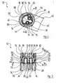
- the guide gap 48 has in cross-section, in the FIG. 2 along the section line II-II from the FIGS. 1 and 3 is shown, overall approximately the shape of an isosceles trapezium with non-straight thighs.
- the wide base side of the trapezoid is open to the side facing away from the water outlet 46 side of the connection portion 44 of the control cartridge 18.
- the legs of the trapezoid are slightly bent outward and cut the respective line receptacle 70 on the side facing away from the other line receptacle 70.
- the water pipes 36 each have, at their ends, one of the circular-cylindrical connecting pieces 74, the outer diameters of which correspond to the inner diameters of the pipe supports 70.
- Each connecting piece 74 is provided with an outer circumferential clamping groove 76 which is aligned with the guide gap 48 in the installed state of the connecting piece 74.
- the bent wire round spring 50 is inserted from the water outlet 46 side facing away from the guide gap 48.
- the clamping spring 50 is in cross section, as in FIG. 2 shown approximately C-shaped and symmetrical with respect to a median plane extending between its legs.
- the legs of the clamping spring 50 are each bent in an S-shape. Viewed at their free ends, the legs each have a convex, outwardly open indentation 86 viewed from the other leg.
- the indentations 86 are in the installed, tensioned state of the clamping spring 50 in the clamping grooves 76 of the connecting pieces 74 at. They embrace the connecting pieces 74, viewed in each case from the other connecting piece 74, partially and thus fix the connecting pieces 74 in the axial direction in the line receptacles 70th
- the legs of the clamping spring 50 are bent inwardly toward each other, so that they slide easily in the clamping grooves 76 of the connecting pieces 74 when inserted into the guide gap 48, wherein they are stretched.
- each connecting piece 74 is also viewed in the longitudinal direction approximately centrally between the clamping groove 76 and the free end of the connecting piece 74, a circumferential sealing groove, in which a sealing ring 78 is arranged. With the sealing rings 78, the cable receptacles 70 are each sealed to the outside to the connection space 34.
- the bottom insert 80 provided with the O-ring seals 56 is inserted into the receiving space 14 so that its peripheral support step 42 bears against the support collar 40.
- the control cartridge 18 is placed on the bottom insert 80.
- the annular screw member 84 is screwed into the thread in the lateral surface of the receiving space 14, whereby the control cartridge 18 presses and fixes the bottom insert 80 against the support collar 40. Then the mixing lever is mounted.
- C-shaped clamping springs 50 of round wire and other types of clamping spring elements for example, rectangular wire or stampings can be used.
- the bottom insert 80 may be made of a different material, such as brass instead of plastic.
Landscapes
- Health & Medical Sciences (AREA)
- Life Sciences & Earth Sciences (AREA)
- Engineering & Computer Science (AREA)
- Hydrology & Water Resources (AREA)
- Public Health (AREA)
- Water Supply & Treatment (AREA)
- Multiple-Way Valves (AREA)
- Valve Housings (AREA)
- Domestic Plumbing Installations (AREA)
Claims (4)
- Robinetterie sanitaire comprenanta) un carter (16) ;b) un espace de réception (14), réservé dans ce dernier et dévolu à une cartouche de commande (18) ;c) une cartouche de commande (18), pouvant être insérée dans ledit espace de réception (14) et pourvue d'un dispositif de raccordement (38) affecté à au moins deux canalisations d'eau (36), ledit dispositif de raccordement (38) comportant des orifices (81) de circulation d'eau qui sont dédiés auxdites canalisations d'eau (36) et sont reliés à des zones correspondantes d'acheminement d'eau, dans ladite cartouche de commande (18) ;d) des logements (70) de canalisations, ménagés dans ledit dispositif de raccordement (38) et dans lesquels les canalisations d'eau (36) sont emboîtées, sachant qu'un élément élastique de coincement (50) pénètre dans des rainures respectives (76) pratiquées dans lesdites canalisations d'eau (36) ;e) un logement de coincement (48) ménagé dans ledit dispositif de raccordement (38), et dans lequel ledit élément élastique de coincement (50) est bloqué à demeure de façon telle qu'il retienne les canalisations d'eau (36) dans les logements (70) desdites canalisations ;caractérisée par le fait quef) l'élément élastique de coincement (50) est interposé entre les canalisations d'eau (36), substantiellement parallèles dans lesdits logements ;g) ledit élément élastique de coincement (50) est arqué avec configuration sensiblement en C, en coupe transversale, et est symétrique par rapport à un plan médian s'étendant entre ses branches, les branches dudit élément élastique de coincement (50) étant respectivement cintrées avec configuration en S, de telle sorte queh) les extrémités desdites branches de l'élément élastique de coincement (50) soient cintrées vers l'intérieur, en direction l'une de l'autre, afin de glisser plus aisément dans les rainures (76) au stade de l'insertion dans le logement de coincement (48), s'opérant avec tension desdites branches.
- Robinetterie sanitaire selon la revendication 1, caractérisée par le fait que les logements (70) des canalisations sont situés dans une pièce intégrée, en particulier une pièce intégrée (80) en matière plastique.
- Robinetterie sanitaire selon la revendication 2, caractérisée par le fait que la pièce intégrée (80) est introduite dans l'espace de réception (14) à partir du côté pointant à l'opposé des canalisations d'eau (36), un arrêt (40, 42), prévenant un ripage, étant prévu pour ladite pièce intégrée (80).
- Robinetterie sanitaire selon la revendication 3, caractérisée par le fait qu'il est prévu un collet d'appui (40) faisant corps avec le carter, la pièce intégrée (80) présentant un épaulement d'appui (42) complémentaire dudit collet d'appui (40) et par lequel ladite pièce intégrée (80) porte contre ledit collet d'appui (40) à partir du côté tourné à l'opposé des canalisations d'eau (36).
Applications Claiming Priority (1)
| Application Number | Priority Date | Filing Date | Title |
|---|---|---|---|
| DE200710006471 DE102007006471B4 (de) | 2007-02-09 | 2007-02-09 | Sanitärarmatur, insbesondere Einhebelmischer |
Publications (3)
| Publication Number | Publication Date |
|---|---|
| EP1956151A2 EP1956151A2 (fr) | 2008-08-13 |
| EP1956151A3 EP1956151A3 (fr) | 2010-05-19 |
| EP1956151B1 true EP1956151B1 (fr) | 2013-12-18 |
Family
ID=39052769
Family Applications (1)
| Application Number | Title | Priority Date | Filing Date |
|---|---|---|---|
| EP08001101.8A Active EP1956151B1 (fr) | 2007-02-09 | 2008-01-22 | Robinetterie sanitaire |
Country Status (2)
| Country | Link |
|---|---|
| EP (1) | EP1956151B1 (fr) |
| DE (1) | DE102007006471B4 (fr) |
Cited By (1)
| Publication number | Priority date | Publication date | Assignee | Title |
|---|---|---|---|---|
| WO2024175217A1 (fr) * | 2023-02-24 | 2024-08-29 | Neoperl Gmbh | Dispositif de fixation pour fixer des tubes sur un appareil sanitaire |
Families Citing this family (2)
| Publication number | Priority date | Publication date | Assignee | Title |
|---|---|---|---|---|
| DE102015002257A1 (de) * | 2015-02-25 | 2016-08-25 | Grohe Ag | Sanitärarmatur mit einer mit einer Klammer befestigten Schlauchverbindung |
| DE102019100678A1 (de) * | 2019-01-11 | 2020-07-16 | Grohe Ag | Sanitärarmatur mit Schlauchbefestigung |
Family Cites Families (7)
| Publication number | Priority date | Publication date | Assignee | Title |
|---|---|---|---|---|
| DE8501281U1 (de) * | 1985-01-19 | 1986-05-22 | Knebel & Röttger GmbH & Co, 5860 Iserlohn | Vorrichtung zur Verbindung von Rohren mit Armaturen |
| DE4415797A1 (de) | 1994-05-05 | 1995-11-09 | Grohe Armaturen Friedrich | Wasserarmatur |
| DE19680949D2 (de) | 1995-11-09 | 1999-01-28 | Ideal Standard | Sanitärarmatur |
| DE19800399C2 (de) * | 1997-12-09 | 2001-02-22 | Ideal Standard | Sanitärarmatur |
| DE19915526C1 (de) | 1999-04-07 | 2000-08-03 | Hansa Metallwerke Ag | Sanitärarmatur |
| DE19941492A1 (de) * | 1999-09-01 | 2001-03-15 | Grohe Armaturen Friedrich | Wasserarmatur mit Anschlussverbindung |
| DE10117992A1 (de) * | 2001-04-10 | 2002-10-17 | Grohe Armaturen Friedrich | Wasserarmatur |
-
2007
- 2007-02-09 DE DE200710006471 patent/DE102007006471B4/de not_active Expired - Fee Related
-
2008
- 2008-01-22 EP EP08001101.8A patent/EP1956151B1/fr active Active
Cited By (1)
| Publication number | Priority date | Publication date | Assignee | Title |
|---|---|---|---|---|
| WO2024175217A1 (fr) * | 2023-02-24 | 2024-08-29 | Neoperl Gmbh | Dispositif de fixation pour fixer des tubes sur un appareil sanitaire |
Also Published As
| Publication number | Publication date |
|---|---|
| EP1956151A3 (fr) | 2010-05-19 |
| DE102007006471A1 (de) | 2008-08-14 |
| EP1956151A2 (fr) | 2008-08-13 |
| DE102007006471B4 (de) | 2009-09-24 |
Similar Documents
| Publication | Publication Date | Title |
|---|---|---|
| EP2957681B1 (fr) | Robinetterie sanitaire a systeme de tuyau interne | |
| DE202013103517U1 (de) | Befestigungsanordnung für einen Wasserhahn | |
| EP3354804B1 (fr) | Dispositif de raccord de tuyau, utilisation d'un dispositif de raccord de tuyau et armature sanitaire | |
| DE102017101566B3 (de) | Schlauchanschlussanordnung, Verwendung einer Schlauchanschlussanordnung und Sanitärarmatur | |
| EP2410228B1 (fr) | Raccord à vis pour tuyaux doté d'un accouplement et d'un économiseur d'eau | |
| WO2014135242A1 (fr) | Régulateur de jet avec raccord de flexible | |
| DE102013003926A1 (de) | Sanitäres Einbauteil, Innenschlauchanordnung für eine Sanitärarmatur und Sanitärarmatur | |
| EP2530365B1 (fr) | Garniture de soupape pour une armature sanitaire | |
| DE102007043309B4 (de) | Sanitärarmatur | |
| DE102016124805B4 (de) | Membranventil | |
| EP1956151B1 (fr) | Robinetterie sanitaire | |
| EP3730705A1 (fr) | Soupape sanitaire | |
| EP2453157B1 (fr) | Système de raccord pour l'installation d'un appareil de conduite de l'eau | |
| DE10324236A1 (de) | Haltevorrichtung für ein Schlauchende | |
| EP0937828A2 (fr) | Robinetterie sanitaire avec raccord de tuyauterie | |
| EP1457607B1 (fr) | Armature sanitaire comportant un dispositif pour fixer une conduite | |
| DE8703606U1 (de) | Auslaufarmatur | |
| EP0859890A1 (fr) | Robinet a usage sanitaire | |
| DE60201028T2 (de) | Selbstschliessende anschlussvorrichtung und endstück dafür | |
| DE102007019627B3 (de) | Messvorrichtung | |
| DE202005004524U1 (de) | Steckverbinder | |
| EP3372887B1 (fr) | Pièce de raccordement | |
| DE29512786U1 (de) | Anschlußstück | |
| EP0780523B1 (fr) | Mitigeur avec conduites d'amenées inclinées | |
| DE102005033665A1 (de) | Aufnahmeteil für einen Stecker |
Legal Events
| Date | Code | Title | Description |
|---|---|---|---|
| PUAI | Public reference made under article 153(3) epc to a published international application that has entered the european phase |
Free format text: ORIGINAL CODE: 0009012 |
|
| AK | Designated contracting states |
Kind code of ref document: A2 Designated state(s): AT BE BG CH CY CZ DE DK EE ES FI FR GB GR HR HU IE IS IT LI LT LU LV MC MT NL NO PL PT RO SE SI SK TR |
|
| AX | Request for extension of the european patent |
Extension state: AL BA MK RS |
|
| PUAL | Search report despatched |
Free format text: ORIGINAL CODE: 0009013 |
|
| AK | Designated contracting states |
Kind code of ref document: A3 Designated state(s): AT BE BG CH CY CZ DE DK EE ES FI FR GB GR HR HU IE IS IT LI LT LU LV MC MT NL NO PL PT RO SE SI SK TR |
|
| AX | Request for extension of the european patent |
Extension state: AL BA MK RS |
|
| AKY | No designation fees paid | ||
| 17P | Request for examination filed |
Effective date: 20101118 |
|
| RBV | Designated contracting states (corrected) |
Designated state(s): AT BE BG CH CY CZ DE DK EE ES FI FR GB GR HR HU IE IS IT LI LT LU LV MC MT NL NO PL PT RO SE SI SK TR |
|
| 17Q | First examination report despatched |
Effective date: 20111125 |
|
| GRAP | Despatch of communication of intention to grant a patent |
Free format text: ORIGINAL CODE: EPIDOSNIGR1 |
|
| INTG | Intention to grant announced |
Effective date: 20130820 |
|
| GRAS | Grant fee paid |
Free format text: ORIGINAL CODE: EPIDOSNIGR3 |
|
| GRAA | (expected) grant |
Free format text: ORIGINAL CODE: 0009210 |
|
| AK | Designated contracting states |
Kind code of ref document: B1 Designated state(s): AT BE BG CH CY CZ DE DK EE ES FI FR GB GR HR HU IE IS IT LI LT LU LV MC MT NL NO PL PT RO SE SI SK TR |
|
| REG | Reference to a national code |
Ref country code: GB Ref legal event code: FG4D Free format text: NOT ENGLISH |
|
| REG | Reference to a national code |
Ref country code: CH Ref legal event code: EP |
|
| REG | Reference to a national code |
Ref country code: AT Ref legal event code: REF Ref document number: 645721 Country of ref document: AT Kind code of ref document: T Effective date: 20140115 |
|
| REG | Reference to a national code |
Ref country code: IE Ref legal event code: FG4D Free format text: LANGUAGE OF EP DOCUMENT: GERMAN |
|
| REG | Reference to a national code |
Ref country code: DE Ref legal event code: R096 Ref document number: 502008011075 Country of ref document: DE Effective date: 20140213 |
|
| REG | Reference to a national code |
Ref country code: CH Ref legal event code: NV Representative=s name: FREI PATENTANWALTSBUERO AG, CH |
|
| REG | Reference to a national code |
Ref country code: NL Ref legal event code: VDEP Effective date: 20131218 |
|
| PG25 | Lapsed in a contracting state [announced via postgrant information from national office to epo] |
Ref country code: HR Free format text: LAPSE BECAUSE OF FAILURE TO SUBMIT A TRANSLATION OF THE DESCRIPTION OR TO PAY THE FEE WITHIN THE PRESCRIBED TIME-LIMIT Effective date: 20131218 Ref country code: SE Free format text: LAPSE BECAUSE OF FAILURE TO SUBMIT A TRANSLATION OF THE DESCRIPTION OR TO PAY THE FEE WITHIN THE PRESCRIBED TIME-LIMIT Effective date: 20131218 Ref country code: NO Free format text: LAPSE BECAUSE OF FAILURE TO SUBMIT A TRANSLATION OF THE DESCRIPTION OR TO PAY THE FEE WITHIN THE PRESCRIBED TIME-LIMIT Effective date: 20140318 Ref country code: LT Free format text: LAPSE BECAUSE OF FAILURE TO SUBMIT A TRANSLATION OF THE DESCRIPTION OR TO PAY THE FEE WITHIN THE PRESCRIBED TIME-LIMIT Effective date: 20131218 Ref country code: FI Free format text: LAPSE BECAUSE OF FAILURE TO SUBMIT A TRANSLATION OF THE DESCRIPTION OR TO PAY THE FEE WITHIN THE PRESCRIBED TIME-LIMIT Effective date: 20131218 |
|
| REG | Reference to a national code |
Ref country code: LT Ref legal event code: MG4D |
|
| PG25 | Lapsed in a contracting state [announced via postgrant information from national office to epo] |
Ref country code: LV Free format text: LAPSE BECAUSE OF FAILURE TO SUBMIT A TRANSLATION OF THE DESCRIPTION OR TO PAY THE FEE WITHIN THE PRESCRIBED TIME-LIMIT Effective date: 20131218 |
|
| BERE | Be: lapsed |
Owner name: HANSA METALLWERKE A.G. Effective date: 20140131 |
|
| PG25 | Lapsed in a contracting state [announced via postgrant information from national office to epo] |
Ref country code: IS Free format text: LAPSE BECAUSE OF FAILURE TO SUBMIT A TRANSLATION OF THE DESCRIPTION OR TO PAY THE FEE WITHIN THE PRESCRIBED TIME-LIMIT Effective date: 20140418 Ref country code: EE Free format text: LAPSE BECAUSE OF FAILURE TO SUBMIT A TRANSLATION OF THE DESCRIPTION OR TO PAY THE FEE WITHIN THE PRESCRIBED TIME-LIMIT Effective date: 20131218 |
|
| PG25 | Lapsed in a contracting state [announced via postgrant information from national office to epo] |
Ref country code: RO Free format text: LAPSE BECAUSE OF FAILURE TO SUBMIT A TRANSLATION OF THE DESCRIPTION OR TO PAY THE FEE WITHIN THE PRESCRIBED TIME-LIMIT Effective date: 20131218 Ref country code: PL Free format text: LAPSE BECAUSE OF FAILURE TO SUBMIT A TRANSLATION OF THE DESCRIPTION OR TO PAY THE FEE WITHIN THE PRESCRIBED TIME-LIMIT Effective date: 20131218 Ref country code: LU Free format text: LAPSE BECAUSE OF FAILURE TO SUBMIT A TRANSLATION OF THE DESCRIPTION OR TO PAY THE FEE WITHIN THE PRESCRIBED TIME-LIMIT Effective date: 20140122 Ref country code: PT Free format text: LAPSE BECAUSE OF FAILURE TO SUBMIT A TRANSLATION OF THE DESCRIPTION OR TO PAY THE FEE WITHIN THE PRESCRIBED TIME-LIMIT Effective date: 20140418 Ref country code: CY Free format text: LAPSE BECAUSE OF FAILURE TO SUBMIT A TRANSLATION OF THE DESCRIPTION OR TO PAY THE FEE WITHIN THE PRESCRIBED TIME-LIMIT Effective date: 20131218 Ref country code: SK Free format text: LAPSE BECAUSE OF FAILURE TO SUBMIT A TRANSLATION OF THE DESCRIPTION OR TO PAY THE FEE WITHIN THE PRESCRIBED TIME-LIMIT Effective date: 20131218 Ref country code: CZ Free format text: LAPSE BECAUSE OF FAILURE TO SUBMIT A TRANSLATION OF THE DESCRIPTION OR TO PAY THE FEE WITHIN THE PRESCRIBED TIME-LIMIT Effective date: 20131218 Ref country code: ES Free format text: LAPSE BECAUSE OF FAILURE TO SUBMIT A TRANSLATION OF THE DESCRIPTION OR TO PAY THE FEE WITHIN THE PRESCRIBED TIME-LIMIT Effective date: 20131218 Ref country code: NL Free format text: LAPSE BECAUSE OF FAILURE TO SUBMIT A TRANSLATION OF THE DESCRIPTION OR TO PAY THE FEE WITHIN THE PRESCRIBED TIME-LIMIT Effective date: 20131218 |
|
| REG | Reference to a national code |
Ref country code: DE Ref legal event code: R097 Ref document number: 502008011075 Country of ref document: DE |
|
| PG25 | Lapsed in a contracting state [announced via postgrant information from national office to epo] |
Ref country code: MC Free format text: LAPSE BECAUSE OF FAILURE TO SUBMIT A TRANSLATION OF THE DESCRIPTION OR TO PAY THE FEE WITHIN THE PRESCRIBED TIME-LIMIT Effective date: 20131218 |
|
| PLBE | No opposition filed within time limit |
Free format text: ORIGINAL CODE: 0009261 |
|
| STAA | Information on the status of an ep patent application or granted ep patent |
Free format text: STATUS: NO OPPOSITION FILED WITHIN TIME LIMIT |
|
| PG25 | Lapsed in a contracting state [announced via postgrant information from national office to epo] |
Ref country code: DK Free format text: LAPSE BECAUSE OF FAILURE TO SUBMIT A TRANSLATION OF THE DESCRIPTION OR TO PAY THE FEE WITHIN THE PRESCRIBED TIME-LIMIT Effective date: 20131218 |
|
| REG | Reference to a national code |
Ref country code: FR Ref legal event code: ST Effective date: 20140930 |
|
| REG | Reference to a national code |
Ref country code: IE Ref legal event code: MM4A |
|
| 26N | No opposition filed |
Effective date: 20140919 |
|
| GBPC | Gb: european patent ceased through non-payment of renewal fee |
Effective date: 20140318 |
|
| PG25 | Lapsed in a contracting state [announced via postgrant information from national office to epo] |
Ref country code: FR Free format text: LAPSE BECAUSE OF NON-PAYMENT OF DUE FEES Effective date: 20140218 |
|
| REG | Reference to a national code |
Ref country code: DE Ref legal event code: R097 Ref document number: 502008011075 Country of ref document: DE Effective date: 20140919 |
|
| PG25 | Lapsed in a contracting state [announced via postgrant information from national office to epo] |
Ref country code: GB Free format text: LAPSE BECAUSE OF NON-PAYMENT OF DUE FEES Effective date: 20140318 Ref country code: IE Free format text: LAPSE BECAUSE OF NON-PAYMENT OF DUE FEES Effective date: 20140122 Ref country code: BE Free format text: LAPSE BECAUSE OF NON-PAYMENT OF DUE FEES Effective date: 20140131 |
|
| PG25 | Lapsed in a contracting state [announced via postgrant information from national office to epo] |
Ref country code: SI Free format text: LAPSE BECAUSE OF FAILURE TO SUBMIT A TRANSLATION OF THE DESCRIPTION OR TO PAY THE FEE WITHIN THE PRESCRIBED TIME-LIMIT Effective date: 20131218 |
|
| PG25 | Lapsed in a contracting state [announced via postgrant information from national office to epo] |
Ref country code: MT Free format text: LAPSE BECAUSE OF FAILURE TO SUBMIT A TRANSLATION OF THE DESCRIPTION OR TO PAY THE FEE WITHIN THE PRESCRIBED TIME-LIMIT Effective date: 20131218 |
|
| PG25 | Lapsed in a contracting state [announced via postgrant information from national office to epo] |
Ref country code: BG Free format text: LAPSE BECAUSE OF FAILURE TO SUBMIT A TRANSLATION OF THE DESCRIPTION OR TO PAY THE FEE WITHIN THE PRESCRIBED TIME-LIMIT Effective date: 20131218 |
|
| PG25 | Lapsed in a contracting state [announced via postgrant information from national office to epo] |
Ref country code: IT Free format text: LAPSE BECAUSE OF FAILURE TO SUBMIT A TRANSLATION OF THE DESCRIPTION OR TO PAY THE FEE WITHIN THE PRESCRIBED TIME-LIMIT Effective date: 20131218 Ref country code: GR Free format text: LAPSE BECAUSE OF FAILURE TO SUBMIT A TRANSLATION OF THE DESCRIPTION OR TO PAY THE FEE WITHIN THE PRESCRIBED TIME-LIMIT Effective date: 20140319 |
|
| PG25 | Lapsed in a contracting state [announced via postgrant information from national office to epo] |
Ref country code: HU Free format text: LAPSE BECAUSE OF FAILURE TO SUBMIT A TRANSLATION OF THE DESCRIPTION OR TO PAY THE FEE WITHIN THE PRESCRIBED TIME-LIMIT; INVALID AB INITIO Effective date: 20080122 Ref country code: TR Free format text: LAPSE BECAUSE OF FAILURE TO SUBMIT A TRANSLATION OF THE DESCRIPTION OR TO PAY THE FEE WITHIN THE PRESCRIBED TIME-LIMIT Effective date: 20131218 |
|
| REG | Reference to a national code |
Ref country code: CH Ref legal event code: PCAR Free format text: NEW ADDRESS: POSTFACH, 8032 ZUERICH (CH) |
|
| PGFP | Annual fee paid to national office [announced via postgrant information from national office to epo] |
Ref country code: CH Payment date: 20230330 Year of fee payment: 16 Ref country code: AT Payment date: 20230322 Year of fee payment: 16 |
|
| P01 | Opt-out of the competence of the unified patent court (upc) registered |
Effective date: 20230513 |
|
| REG | Reference to a national code |
Ref country code: CH Ref legal event code: PL |
|
| REG | Reference to a national code |
Ref country code: AT Ref legal event code: MM01 Ref document number: 645721 Country of ref document: AT Kind code of ref document: T Effective date: 20240122 |
|
| PG25 | Lapsed in a contracting state [announced via postgrant information from national office to epo] |
Ref country code: CH Free format text: LAPSE BECAUSE OF NON-PAYMENT OF DUE FEES Effective date: 20240131 |
|
| PG25 | Lapsed in a contracting state [announced via postgrant information from national office to epo] |
Ref country code: AT Free format text: LAPSE BECAUSE OF NON-PAYMENT OF DUE FEES Effective date: 20240122 |
|
| PG25 | Lapsed in a contracting state [announced via postgrant information from national office to epo] |
Ref country code: CH Free format text: LAPSE BECAUSE OF NON-PAYMENT OF DUE FEES Effective date: 20240131 Ref country code: AT Free format text: LAPSE BECAUSE OF NON-PAYMENT OF DUE FEES Effective date: 20240122 |
|
| PGFP | Annual fee paid to national office [announced via postgrant information from national office to epo] |
Ref country code: DE Payment date: 20241231 Year of fee payment: 18 |