EP1956215A2 - Turbine à gaz comprenant un circuit de refroidissement isolé - Google Patents
Turbine à gaz comprenant un circuit de refroidissement isolé Download PDFInfo
- Publication number
- EP1956215A2 EP1956215A2 EP08101137A EP08101137A EP1956215A2 EP 1956215 A2 EP1956215 A2 EP 1956215A2 EP 08101137 A EP08101137 A EP 08101137A EP 08101137 A EP08101137 A EP 08101137A EP 1956215 A2 EP1956215 A2 EP 1956215A2
- Authority
- EP
- European Patent Office
- Prior art keywords
- gas turbine
- turbine engine
- tubes
- passages
- stator
- Prior art date
- Legal status (The legal status is an assumption and is not a legal conclusion. Google has not performed a legal analysis and makes no representation as to the accuracy of the status listed.)
- Granted
Links
Images

Classifications
-
- F—MECHANICAL ENGINEERING; LIGHTING; HEATING; WEAPONS; BLASTING
- F01—MACHINES OR ENGINES IN GENERAL; ENGINE PLANTS IN GENERAL; STEAM ENGINES
- F01D—NON-POSITIVE DISPLACEMENT MACHINES OR ENGINES, e.g. STEAM TURBINES
- F01D9/00—Stators
- F01D9/06—Fluid supply conduits to nozzles or the like
- F01D9/065—Fluid supply or removal conduits traversing the working fluid flow, e.g. for lubrication-, cooling-, or sealing fluids
-
- F—MECHANICAL ENGINEERING; LIGHTING; HEATING; WEAPONS; BLASTING
- F02—COMBUSTION ENGINES; HOT-GAS OR COMBUSTION-PRODUCT ENGINE PLANTS
- F02C—GAS-TURBINE PLANTS; AIR INTAKES FOR JET-PROPULSION PLANTS; CONTROLLING FUEL SUPPLY IN AIR-BREATHING JET-PROPULSION PLANTS
- F02C6/00—Plural gas-turbine plants; Combinations of gas-turbine plants with other apparatus; Adaptations of gas-turbine plants for special use
- F02C6/04—Gas-turbine plants providing heated or pressurised working fluid for other apparatus, e.g. without mechanical power output
- F02C6/06—Gas-turbine plants providing heated or pressurised working fluid for other apparatus, e.g. without mechanical power output providing compressed gas
- F02C6/08—Gas-turbine plants providing heated or pressurised working fluid for other apparatus, e.g. without mechanical power output providing compressed gas the gas being bled from the gas-turbine compressor
-
- F—MECHANICAL ENGINEERING; LIGHTING; HEATING; WEAPONS; BLASTING
- F05—INDEXING SCHEMES RELATING TO ENGINES OR PUMPS IN VARIOUS SUBCLASSES OF CLASSES F01-F04
- F05D—INDEXING SCHEME FOR ASPECTS RELATING TO NON-POSITIVE-DISPLACEMENT MACHINES OR ENGINES, GAS-TURBINES OR JET-PROPULSION PLANTS
- F05D2260/00—Function
- F05D2260/20—Heat transfer, e.g. cooling
- F05D2260/231—Preventing heat transfer
Definitions
- This invention relates generally to cooling circuits in gas turbine engines.
- this invention relates to a device for providing cooling air to a gas turbine engine, comprising a insulation barrier to reduce the heat pickup by the cooling air from the surrounding hot gases.
- Gas turbine engines are one of the most efficient means of producing energy. Gas turbine power, efficiency, and economics generally increase when the temperature of gas flowing through the turbine increases. A limiting factor of most gas turbine engines is the turbine inlet temperature, however, because the blade metal temperature generally must be kept below 1400°F to avoid hot corrosion problems.
- Air cooling technology bleeds cooling air from the compressor and directs the cooling air to the stator, rotor, and other parts of the rotor and casing.
- a gas turbine engine comprising a compressor comprising an insulated cooling circuit, a combustor, and a turbine.
- the compressor comprises a compressor casing having a compression chamber and at least one stator and at least one rotor disposed in the compression chamber.
- the at least one stator comprises a stator body having a plurality of passages extending therethrough from an outwardly positioned opening to an inwardly positioned opening, and a plurality of tubes for transporting cooling air through the stator body into the compression chamber.
- the plurality of tubes extend through the respective plurality of passages from an inlet to an outlet and are spaced from walls of the respective passages to form an air gap between each tube and walls of the respective passages.
- the insulated cooling circuit further comprises at least one spacer between the plurality of tubes and the walls of the respective passages.
- the stagnant air gap comprises a high temperature insulation to further reduce heat transfer between the hot gas of the gas turbine engine and the cooling air of the cooling circuit.
- a compressor of a gas turbine engine comprising an insulated cooling circuit.
- the insulated cooling circuit minimizes the heat pickup of the cooling air, and accordingly, requires less cooling air to maximize cycle efficiency and power output. Embodiments of this invention are described in detail below and are illustrated in Fig. 1-5 .
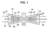
- a typical gas turbine engine 110 illustrated in Fig. 1 , comprises a compressor 112 in serial flow communication with a combustor 114, and a turbine 116.
- the compressor 112 and turbine 116 may be coupled by a driveshaft 117, which also may couple the turbine 116 and drive an electrical generator (not shown).
- the turbine further may comprise compressor and turbine casings 118, 120, which enclose a compressor chamber 119 and a turbine chamber 121, respectively.
- the gas turbine engine 110 may be any engine which is commercially available from the General Electric Company, although the gas turbine engine 110 illustrated and described herein is exemplary only. Accordingly, the gas turbine engine 110 is not limited to the gas turbine engine as shown in Figure 1 and described herein, but rather, may be any gas turbine known to those of ordinary skill in the art.
- the gas turbine engine 110 may comprise a multi-shaft gas turbine engine having two shafts for separately driving an electrical generator (not shown) and the compressor 112.
- air may flow into the gas turbine engine 110 through the compressor chamber 119 and may be compressed. Compressed air then may be channeled to the combustor 114 where it may be mixed with fuel (not shown) and ignited. The expanding hot gases from the combustor 114 may drive the rotating turbine 116 and may exit (as indicated by arrows 124) the gas turbine engine 110 through an exhaust diffuser (not shown). Additionally, in some embodiments, exhaust gases from the turbine engine 110 may be supplied to a heat recovery steam generator (not shown) that generates steam for driving a steam turbine (not shown).
- the compressor 112 illustrated in Figs. 1 and 2 , generally comprises the compressor casing 118 having the compressor chamber 119 and at least one rotor 126 and at least one stator 128 disposed in the compression chamber.
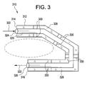
- the at least one stator 128 comprises a stator body 210 having an insulated cooling circuit 310, illustrated in Fig. 3 .
- the stator body 210 comprises a plurality of passages 312 extending therethrough, as represented by the broken lines of Fig. 2 .
- the plurality of passages 312 have an outwardly positioned opening 314 and an inwardly positioned opening 316 in the stator body 210.
- the outwardly positioned opening 314 is located further from the central region 318 of the gas turbine engine 110 than is the inwardly positioned opening 316.
- the stator body 210 further comprises a plurality of tubes 320 for transporting a cooling air (as indicated by arrows) 322 to the compression chamber 119.
- the plurality of tubes 320 transport the cooling air 322 to a central region (as indicated by the dashed lines) 318 of the gas turbine engine 110 near and about the driveshaft 117.
- the plurality of tubes 320 extend through the respective plurality of passages 312 from respective inlets 324 to respective outlets 326 in the central region 318 of the gas turbine engine 110, and desirably proximate the inwardly positioned opening 316 so that the cooling air 322 flows from the outlets into the central region of the gas turbine engine.
- proximate means that the outlets 326 of the plurality of tubes 320 are contiguous or nearly contiguous with the inwardly positioned openings 316.
- the plurality of tubes 320 are spaced from the walls of the respective plurality of passages 312 to form an air gap 328 between the tubes and walls of the respective passages.
- the air gap 328 is stagnant, meaning that the air gap comprises a pocket of air without the flow of any air, thereby restricting the mode of heat transfer through the stagnant air gap to natural convection. Accordingly, the stagnant air gap 328 provides an insulation barrier for the plurality of tubes 320, thereby minimizing the heat transfer between the stator body 210 and the plurality of tubes 320 transporting the cooling air 322.
- stator body 210 further comprises a plurality of spacers 330 disposed in the passages 312 for spacing the tubes 320 from the walls of the passages 312.
- stator body 210 further comprises a high temperature insulation disposed in the air gap 328 between the tubes 320 and the walls of the passages 312.
- the plurality of tubes 320 are welded to the stator body 210. In an alternative embodiment, the plurality of tubes 320 are fastened to the stator body 210 with an air-tight tube fitting.
- the plurality of tubes 320 comprise walls having a thickness from about 0.040 inches to about 0.080 inches.
- the plurality of tubes 320 comprise materials that are resistant to high temperatures and corrosion.
- the plurality of tubes 320 comprise a nickel alloy.
- the plurality of tubes 320 comprises stainless steel.
- the stator 128 comprises materials that are high strength and resistant to high temperatures and corrosion.
- the stator 128 comprises CrMoV.
- the stator 128 comprises cast iron or carbon steel.
- the spacers 330 generally comprise materials that are resistant to high temperatures and wear.
- the spacers 330 comprise a cobalt alloy.
- the spacers 330 comprise a nickel alloy or stainless steel.
- the air gap 328 desirably has a thickness (t) (illustrated in Figs. 5A-5C ) in the range of about 0.040 inches to about 0.080 inches. In one embodiment, the air gap 328 has a thickness of about 0.050 inches.
- the air gap 328 minimizes the heat pickup of the cooling air 322 between the inlet 324 and outlet 326 of the tubes 320. In one embodiment, the temperature change of the cooling air 322 between the inlet 324 and outlet 326 is no more than about 100°F, more desirably no more than about 50°F, even more desirably no more than about 25°F, and still even more desirably no more than about 10°F.
- the flow rate of the cooling air 322 is in the range of about 2.0 lbm/sec/channel to about 3.0 lbm/sec/channel and the inlet 324 temperature of the cooling air 322 is in the range of about 500°F to about 650°F.
- the compressor 112 comprises a compressor casing 118 having a compression chamber 119 and comprises at least one stator 128 disposed in the compression chamber 119.
- the at least one stator generally comprises a stator body 210 having a plurality of passages 312 having an outwardly positioned opening 314 and an inwardly positioned opening 316.
- a cooling air 322 is transported through a plurality of tubes 320, which extend from respective inlets 324 through the plurality of passages 312, 324 to respective outlets 326 proximate the inwardly positioned opening 316.
- the plurality of tubes 320 are welded or fastened by air-tight tube fittings to the walls of the passages 312. Spacers 330 between the tubes 320 and the walls of the passages 312 establish a desired stagnant air gap 328.
- the stagnant air gap 328 provides an insulation barrier to the cooling air 322 flowing through the plurality of tubes 320.
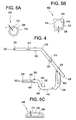
- a first length of tube 410 comprises a horizontal tube, the cross-section 412 of which is illustrated in Fig. 5A .
- the first length of tube 410 joins a second length of tube 414 at an elbow 416, the second length of tube comprising an inclined tube.
- the second length of tube 414 fits within a U shaped slot 418 sealed by a welded plate 420, the cross-section 422 of which is illustrated in Fig. 5B .
- Two holes 424 in the side of the second length of tube 414 join a third length of tube 426, the third length of tube comprising two parallel tubes.
- the end of the second length of tube 414 is sealed with an end cap 428.
- the third length of tube 426 directs the cooling air into a elbow cavity 430 that directs the cooling air into a fourth length of tube 432, the fourth length of tube comprising a horizontal tube.
- the fourth length of tube 432 comprises a diffuser-like turning guide 434, which minimizes energy loss and directs the cooling air into the fifth length of tube 436.
- the fifth length of tube 436 comprises a flat channel, the cross-section 438 of which is illustrated in Fig. 5C , leading to the outlet 326 at the central region of the gas turbine engine 318.
- This particular embodiment of an insulated tube passage system resulted in a 93% reduction in the temperature change of the cooling air between the inlet at the external casing of the stator and the outlet at the engine centerline region when compared to the prior art with a identical mass flow rate. Accordingly, for the same outlet temperature of cooling air, a smaller heat exchanger can be used to cool the compressor discharge temperature due to the fact that the inlet temperature of the cooling air can be set to a much higher value. With the same mass flow rate of cooling air, the insulated tube passage system will reject less heat to the bottoming cycle and thereby increase the combined cycle thermal efficiency and power output.
Landscapes
- Engineering & Computer Science (AREA)
- Mechanical Engineering (AREA)
- General Engineering & Computer Science (AREA)
- Physics & Mathematics (AREA)
- Fluid Mechanics (AREA)
- Chemical & Material Sciences (AREA)
- Combustion & Propulsion (AREA)
- Structures Of Non-Positive Displacement Pumps (AREA)
- Turbine Rotor Nozzle Sealing (AREA)
- Motor Or Generator Cooling System (AREA)
Applications Claiming Priority (1)
| Application Number | Priority Date | Filing Date | Title |
|---|---|---|---|
| US11/671,933 US8182205B2 (en) | 2007-02-06 | 2007-02-06 | Gas turbine engine with insulated cooling circuit |
Publications (3)
| Publication Number | Publication Date |
|---|---|
| EP1956215A2 true EP1956215A2 (fr) | 2008-08-13 |
| EP1956215A3 EP1956215A3 (fr) | 2014-08-27 |
| EP1956215B1 EP1956215B1 (fr) | 2019-03-13 |
Family
ID=39102336
Family Applications (1)
| Application Number | Title | Priority Date | Filing Date |
|---|---|---|---|
| EP08101137.1A Active EP1956215B1 (fr) | 2007-02-06 | 2008-01-31 | Turbine à gaz comprenant un circuit de refroidissement isolé |
Country Status (3)
| Country | Link |
|---|---|
| US (1) | US8182205B2 (fr) |
| EP (1) | EP1956215B1 (fr) |
| JP (1) | JP5328167B2 (fr) |
Cited By (1)
| Publication number | Priority date | Publication date | Assignee | Title |
|---|---|---|---|---|
| EP3550106A1 (fr) * | 2018-04-06 | 2019-10-09 | Frederick M. Schwarz | Air de refroidissement pour moteur à turbine à gaz avec distribution d'air de refroidissement isolé thermiquement |
Families Citing this family (7)
| Publication number | Priority date | Publication date | Assignee | Title |
|---|---|---|---|---|
| US9279341B2 (en) | 2011-09-22 | 2016-03-08 | Pratt & Whitney Canada Corp. | Air system architecture for a mid-turbine frame module |
| US9194257B2 (en) | 2012-08-08 | 2015-11-24 | General Electric Company | Turbine conduit sleeve system |
| EP3047108B8 (fr) * | 2013-09-17 | 2021-03-31 | Raytheon Technologies Corporation | Ensemble de profil aérodynamique constitué par un matériau résistant aux températures élevées |
| GB201321614D0 (en) * | 2013-12-06 | 2014-01-22 | Eaton Ltd | Onboard inert gas generation system |
| KR101509382B1 (ko) | 2014-01-15 | 2015-04-07 | 두산중공업 주식회사 | 댐핑 클램프를 구비한 가스 터빈 |
| US10100738B2 (en) * | 2015-01-20 | 2018-10-16 | United Technologies Corporation | Overcooled air cooling system with annular mixing passage |
| US10273812B2 (en) | 2015-12-18 | 2019-04-30 | Pratt & Whitney Canada Corp. | Turbine rotor coolant supply system |
Family Cites Families (25)
| Publication number | Priority date | Publication date | Assignee | Title |
|---|---|---|---|---|
| US2680001A (en) * | 1950-11-13 | 1954-06-01 | United Aircraft Corp | Arrangement for cooling turbine bearings |
| GB742241A (en) * | 1951-02-15 | 1955-12-21 | Power Jets Res & Dev Ltd | Improvements in the cooling of turbines |
| US2780435A (en) * | 1953-01-12 | 1957-02-05 | Jackson Thomas Woodrow | Turbine blade cooling structure |
| US3045965A (en) * | 1959-04-27 | 1962-07-24 | Rolls Royce | Turbine blades, vanes and the like |
| US3271004A (en) * | 1965-06-22 | 1966-09-06 | Smuland Robert John | Turbine vane adapted for high temperature operation |
| DE1957614C3 (de) * | 1969-11-15 | 1974-03-14 | Motoren- Und Turbinen-Union Muenchen Gmbh, 8000 Muenchen | Laufschaufelkranz für Gasturbinentriebwerke mit hoher DrehzahL |
| US4162136A (en) * | 1974-04-05 | 1979-07-24 | Rolls-Royce Limited | Cooled blade for a gas turbine engine |
| US4156582A (en) * | 1976-12-13 | 1979-05-29 | General Electric Company | Liquid cooled gas turbine buckets |
| GB1555587A (en) * | 1977-07-22 | 1979-11-14 | Rolls Royce | Aerofoil blade for a gas turbine engine |
| US4418455A (en) * | 1981-05-04 | 1983-12-06 | Electric Power Research Institute, Inc. | Method of manufacturing a fluid cooled blade or vane |
| US4492517A (en) * | 1983-01-06 | 1985-01-08 | General Electric Company | Segmented inlet nozzle for gas turbine, and methods of installation |
| JPH01315698A (ja) * | 1988-06-15 | 1989-12-20 | Toshiba Corp | 軸流圧縮機 |
| US5212940A (en) * | 1991-04-16 | 1993-05-25 | General Electric Company | Tip clearance control apparatus and method |
| GB2263946A (en) * | 1992-02-04 | 1993-08-11 | Bmw Rolls Royce Gmbh | An arrangement for supplying cooling air to a gas turbine casing. |
| DE4411616C2 (de) * | 1994-04-02 | 2003-04-17 | Alstom | Verfahren zum Betreiben einer Strömungsmaschine |
| JPH08270459A (ja) * | 1995-03-30 | 1996-10-15 | Hitachi Ltd | ガスタービン設備及びガスタービン設備運転方法 |
| JPH11315800A (ja) * | 1998-04-30 | 1999-11-16 | Toshiba Corp | 空気圧縮機 |
| ITMI991208A1 (it) * | 1999-05-31 | 2000-12-01 | Nuovo Pignone Spa | Dispositivo per il posizionamento di ugelli di uno stadio statorico eper il raffreddamento di dischi rotorici in turbine a gas |
| US6398518B1 (en) * | 2000-03-29 | 2002-06-04 | Watson Cogeneration Company | Method and apparatus for increasing the efficiency of a multi-stage compressor |
| EP1180578A1 (fr) * | 2000-08-16 | 2002-02-20 | Siemens Aktiengesellschaft | Aubes statoriques pour une turbomachine |
| US6644921B2 (en) * | 2001-11-08 | 2003-11-11 | General Electric Company | Cooling passages and methods of fabrication |
| JP2003314299A (ja) * | 2002-04-23 | 2003-11-06 | Toshiba Corp | ガスタービン |
| US6884023B2 (en) * | 2002-09-27 | 2005-04-26 | United Technologies Corporation | Integral swirl knife edge injection assembly |
| US7033135B2 (en) * | 2003-11-10 | 2006-04-25 | General Electric Company | Method and apparatus for distributing fluid into a turbomachine |
| DE502004007566D1 (de) * | 2004-09-22 | 2008-08-21 | Siemens Ag | Kühlsystem für eine Gasturbine und Verfahren zum Kühlen einer Gasturbine |
-
2007
- 2007-02-06 US US11/671,933 patent/US8182205B2/en active Active
-
2008
- 2008-01-31 EP EP08101137.1A patent/EP1956215B1/fr active Active
- 2008-02-04 JP JP2008023422A patent/JP5328167B2/ja active Active
Cited By (3)
| Publication number | Priority date | Publication date | Assignee | Title |
|---|---|---|---|---|
| EP3550106A1 (fr) * | 2018-04-06 | 2019-10-09 | Frederick M. Schwarz | Air de refroidissement pour moteur à turbine à gaz avec distribution d'air de refroidissement isolé thermiquement |
| US11428121B2 (en) | 2018-04-06 | 2022-08-30 | Raytheon Technologies Corporation | Cooling air for gas turbine engine with thermally isolated cooling air delivery |
| US11920485B2 (en) | 2018-04-06 | 2024-03-05 | Rtx Corporation | Cooling air for gas turbine engine with thermally isolated cooling air delivery |
Also Published As
| Publication number | Publication date |
|---|---|
| US8182205B2 (en) | 2012-05-22 |
| JP2008190530A (ja) | 2008-08-21 |
| EP1956215B1 (fr) | 2019-03-13 |
| EP1956215A3 (fr) | 2014-08-27 |
| US20090324397A1 (en) | 2009-12-31 |
| JP5328167B2 (ja) | 2013-10-30 |
Similar Documents
| Publication | Publication Date | Title |
|---|---|---|
| EP1956215B1 (fr) | Turbine à gaz comprenant un circuit de refroidissement isolé | |
| CN106050427B (zh) | 用于涡轮机的热管温度管理系统 | |
| EP3196443B1 (fr) | Groupement d'échangeur de chaleur | |
| US8858161B1 (en) | Multiple staged compressor with last stage airfoil cooling | |
| EP2358978B1 (fr) | Appareil et procédé de refroidissement d un agencement de partie profilée de turbine dans une turbine à gaz | |
| EP1543219B1 (fr) | Conception de refroidissement faisant intervenir un generateur de turbulences pour une aube de turbine | |
| EP3075953A1 (fr) | Système de gestion de température à caloduc pour une turbomachine | |
| EP3499170A1 (fr) | Entrée d'embouchure de cloche d'échangeur de chaleur | |
| CN101178027A (zh) | 操作燃气轮机换热器的方法和装置 | |
| JP2002322915A (ja) | ガスタービン | |
| US8794907B1 (en) | Multiple staged compressor with last stage airfoil cooling | |
| KR20140066105A (ko) | 구동 어셈블리의 과급 장치 | |
| US7137784B2 (en) | Thermally loaded component | |
| CN104246373B (zh) | 燃气涡轮机 | |
| EP3168431A1 (fr) | Échangeurs de chaleur et procédés de refroidissement de turbines à gaz | |
| CN102042041A (zh) | 用于冷却蒸汽涡轮机转子的系统和方法 | |
| CN106050429A (zh) | 用于涡轮机的热管中间冷却系统 | |
| EP3390780B1 (fr) | Système de refroidissement pour des disques de couple de châssis intermédiaire en aval d'un ensemble compresseur dans un moteur à turbine à gaz | |
| US8721265B1 (en) | Multiple staged compressor with last stage airfoil cooling | |
| EP0313194B1 (fr) | Conduit entre turbines | |
| CN104379876A (zh) | 用于燃气轮机的、能够插入在空心的、被冷却的涡轮叶片中的冷却剂桥接管道 | |
| KR101772837B1 (ko) | 가스터빈 연소기 및 해당 연소기를 구비한 가스터빈 | |
| US10294810B2 (en) | Heat exchanger seal segment for a gas turbine engine | |
| EP3354878B1 (fr) | Échangeur de chaleur pour moteur à turbine à gaz | |
| US11834993B1 (en) | Engine exhaust reverse flow prevention |
Legal Events
| Date | Code | Title | Description |
|---|---|---|---|
| PUAI | Public reference made under article 153(3) epc to a published international application that has entered the european phase |
Free format text: ORIGINAL CODE: 0009012 |
|
| AK | Designated contracting states |
Kind code of ref document: A2 Designated state(s): AT BE BG CH CY CZ DE DK EE ES FI FR GB GR HR HU IE IS IT LI LT LU LV MC MT NL NO PL PT RO SE SI SK TR |
|
| AX | Request for extension of the european patent |
Extension state: AL BA MK RS |
|
| PUAL | Search report despatched |
Free format text: ORIGINAL CODE: 0009013 |
|
| AK | Designated contracting states |
Kind code of ref document: A3 Designated state(s): AT BE BG CH CY CZ DE DK EE ES FI FR GB GR HR HU IE IS IT LI LT LU LV MC MT NL NO PL PT RO SE SI SK TR |
|
| AX | Request for extension of the european patent |
Extension state: AL BA MK RS |
|
| RIC1 | Information provided on ipc code assigned before grant |
Ipc: F02C 7/18 20060101AFI20140721BHEP |
|
| 17P | Request for examination filed |
Effective date: 20150227 |
|
| RBV | Designated contracting states (corrected) |
Designated state(s): AT BE BG CH CY CZ DE DK EE ES FI FR GB GR HR HU IE IS IT LI LT LU LV MC MT NL NO PL PT RO SE SI SK TR |
|
| AKX | Designation fees paid |
Designated state(s): DE FR GB IT |
|
| AXX | Extension fees paid |
Extension state: MK Extension state: RS Extension state: BA Extension state: AL |
|
| 17Q | First examination report despatched |
Effective date: 20150713 |
|
| GRAP | Despatch of communication of intention to grant a patent |
Free format text: ORIGINAL CODE: EPIDOSNIGR1 |
|
| INTG | Intention to grant announced |
Effective date: 20181112 |
|
| GRAS | Grant fee paid |
Free format text: ORIGINAL CODE: EPIDOSNIGR3 |
|
| GRAA | (expected) grant |
Free format text: ORIGINAL CODE: 0009210 |
|
| AK | Designated contracting states |
Kind code of ref document: B1 Designated state(s): DE FR GB IT |
|
| REG | Reference to a national code |
Ref country code: GB Ref legal event code: FG4D |
|
| REG | Reference to a national code |
Ref country code: DE Ref legal event code: R096 Ref document number: 602008059313 Country of ref document: DE |
|
| REG | Reference to a national code |
Ref country code: DE Ref legal event code: R097 Ref document number: 602008059313 Country of ref document: DE |
|
| PLBE | No opposition filed within time limit |
Free format text: ORIGINAL CODE: 0009261 |
|
| STAA | Information on the status of an ep patent application or granted ep patent |
Free format text: STATUS: NO OPPOSITION FILED WITHIN TIME LIMIT |
|
| 26N | No opposition filed |
Effective date: 20191216 |
|
| PGFP | Annual fee paid to national office [announced via postgrant information from national office to epo] |
Ref country code: GB Payment date: 20191224 Year of fee payment: 13 |
|
| GBPC | Gb: european patent ceased through non-payment of renewal fee |
Effective date: 20210131 |
|
| PG25 | Lapsed in a contracting state [announced via postgrant information from national office to epo] |
Ref country code: GB Free format text: LAPSE BECAUSE OF NON-PAYMENT OF DUE FEES Effective date: 20210131 |
|
| PGFP | Annual fee paid to national office [announced via postgrant information from national office to epo] |
Ref country code: FR Payment date: 20211215 Year of fee payment: 15 |
|
| REG | Reference to a national code |
Ref country code: DE Ref legal event code: R081 Ref document number: 602008059313 Country of ref document: DE Owner name: GENERAL ELECTRIC TECHNOLOGY GMBH, CH Free format text: FORMER OWNER: GENERAL ELECTRIC COMPANY, SCHENECTADY, NY, US |
|
| PG25 | Lapsed in a contracting state [announced via postgrant information from national office to epo] |
Ref country code: FR Free format text: LAPSE BECAUSE OF NON-PAYMENT OF DUE FEES Effective date: 20230131 |
|
| PGFP | Annual fee paid to national office [announced via postgrant information from national office to epo] |
Ref country code: DE Payment date: 20251217 Year of fee payment: 19 |
|
| PGFP | Annual fee paid to national office [announced via postgrant information from national office to epo] |
Ref country code: IT Payment date: 20260107 Year of fee payment: 19 |