EP1956224A2 - Tuyère à section variable pour une nacelle de turbomoteur avec un système de mise en action à anneau d'entraînement à came - Google Patents
Tuyère à section variable pour une nacelle de turbomoteur avec un système de mise en action à anneau d'entraînement à came Download PDFInfo
- Publication number
- EP1956224A2 EP1956224A2 EP08250456A EP08250456A EP1956224A2 EP 1956224 A2 EP1956224 A2 EP 1956224A2 EP 08250456 A EP08250456 A EP 08250456A EP 08250456 A EP08250456 A EP 08250456A EP 1956224 A2 EP1956224 A2 EP 1956224A2
- Authority
- EP
- European Patent Office
- Prior art keywords
- fan
- engine
- cam
- drive ring
- flap
- Prior art date
- Legal status (The legal status is an assumption and is not a legal conclusion. Google has not performed a legal analysis and makes no representation as to the accuracy of the status listed.)
- Granted
Links
Images




Classifications
-
- F—MECHANICAL ENGINEERING; LIGHTING; HEATING; WEAPONS; BLASTING
- F02—COMBUSTION ENGINES; HOT-GAS OR COMBUSTION-PRODUCT ENGINE PLANTS
- F02K—JET-PROPULSION PLANTS
- F02K3/00—Plants including a gas turbine driving a compressor or a ducted fan
- F02K3/02—Plants including a gas turbine driving a compressor or a ducted fan in which part of the working fluid by-passes the turbine and combustion chamber
- F02K3/04—Plants including a gas turbine driving a compressor or a ducted fan in which part of the working fluid by-passes the turbine and combustion chamber the plant including ducted fans, i.e. fans with high volume, low pressure outputs, for augmenting the jet thrust, e.g. of double-flow type
- F02K3/06—Plants including a gas turbine driving a compressor or a ducted fan in which part of the working fluid by-passes the turbine and combustion chamber the plant including ducted fans, i.e. fans with high volume, low pressure outputs, for augmenting the jet thrust, e.g. of double-flow type with front fan
-
- F—MECHANICAL ENGINEERING; LIGHTING; HEATING; WEAPONS; BLASTING
- F02—COMBUSTION ENGINES; HOT-GAS OR COMBUSTION-PRODUCT ENGINE PLANTS
- F02K—JET-PROPULSION PLANTS
- F02K1/00—Plants characterised by the form or arrangement of the jet pipe or nozzle; Jet pipes or nozzles peculiar thereto
- F02K1/002—Plants characterised by the form or arrangement of the jet pipe or nozzle; Jet pipes or nozzles peculiar thereto with means to modify the direction of thrust vector
-
- F—MECHANICAL ENGINEERING; LIGHTING; HEATING; WEAPONS; BLASTING
- F02—COMBUSTION ENGINES; HOT-GAS OR COMBUSTION-PRODUCT ENGINE PLANTS
- F02K—JET-PROPULSION PLANTS
- F02K1/00—Plants characterised by the form or arrangement of the jet pipe or nozzle; Jet pipes or nozzles peculiar thereto
- F02K1/06—Varying effective area of jet pipe or nozzle
- F02K1/12—Varying effective area of jet pipe or nozzle by means of pivoted flaps
- F02K1/1207—Varying effective area of jet pipe or nozzle by means of pivoted flaps of one series of flaps hinged at their upstream ends on a fixed structure
-
- Y—GENERAL TAGGING OF NEW TECHNOLOGICAL DEVELOPMENTS; GENERAL TAGGING OF CROSS-SECTIONAL TECHNOLOGIES SPANNING OVER SEVERAL SECTIONS OF THE IPC; TECHNICAL SUBJECTS COVERED BY FORMER USPC CROSS-REFERENCE ART COLLECTIONS [XRACs] AND DIGESTS
- Y10—TECHNICAL SUBJECTS COVERED BY FORMER USPC
- Y10T—TECHNICAL SUBJECTS COVERED BY FORMER US CLASSIFICATION
- Y10T74/00—Machine element or mechanism
- Y10T74/21—Elements
- Y10T74/2101—Cams
Definitions
- the present invention relates to a gas turbine engine, and more particularly to a turbofan engine having an axial and rotationally moveable drive ring to provide symmetrical and asymmetrical control of the fan nozzle exit area and the direction of the engine thrust vector.
- Conventional gas turbine engines generally include a fan section and a core engine with the fan section having a larger diameter than that of the core engine.
- the fan section and the core engine are disposed about a longitudinal axis and are enclosed within an engine nacelle assembly.
- Combustion gases are discharged from the core engine through a core exhaust nozzle while an annular fan flow, disposed radially outward of the primary airflow path, is discharged through an annular fan exhaust nozzle defined between an outer fan nacelle and an inner core nacelle.
- a majority of thrust is produced by the pressurized fan air discharged through the fan exhaust nozzle, the remaining thrust being provided from the combustion gases discharged through the core exhaust nozzle.
- the fan nozzles of conventional gas turbine engines have a fixed geometry.
- the fixed geometry fan nozzles are a compromise suitable for take-off and landing conditions as well as for cruise conditions.
- Some gas turbine engines have implemented fan variable area nozzles.
- the fan variable area nozzles provide a smaller fan exit nozzle area during cruise conditions and a larger fan exit nozzle area during take-off and landing conditions.
- Existing fan variable area nozzles typically utilize relatively complex mechanisms that increase overall engine weight to the extent that the increased fuel efficiency therefrom may be negated.
- a fan variable area nozzle disclosed herein includes a flap assembly which varies a fan nozzle exit area.
- the flap assembly is incorporated into an end segment of the fan nacelle to include a trailing edge thereof.
- the flap assembly generally includes a multiple of flaps, flap linkages and an actuator system.
- the actuator system rotationally translates a cam drive ring which drives the flap linkage of each flap to symmetrically vary the fan nozzle exit area.
- a multiple of actuators rotate the cam drive ring which results in a follower of the flap linkage following a cam surface to pivot each flap such that the FVAN symmetrically dilates.
- Rotation of the cam drive ring adjusts dilation of the entire fan nozzle exit area in a symmetrical manner.
- the cam drive ring includes a multiple of movable cams which engages the follower of the flap linkage of each flap. Pivoting of a particular number of the multiple of movable cams results in vectoring of the FVAN.
- the present invention therefore provides an effective, lightweight fan variable area nozzle and thrust vectoring system for a gas turbine engine.
- Figure 1A illustrates a general partial fragmentary schematic view of a gas turbofan engine 10 suspended from an engine pylon P within an engine nacelle assembly N as is typical of an aircraft designed for subsonic operation.
- the turbofan engine 10 includes a core engine within a core nacelle 12 that houses a low spool 14 and high spool 24.
- the low spool 14 includes a low pressure compressor 16 and low pressure turbine 18.
- the low spool 14 drives a fan 20 through a gear train 22.
- the high spool 24 includes a high pressure compressor 26 and high pressure turbine 28.
- a combustor 30 resides between the high pressure compressor 26 and high pressure turbine 28.
- the low and high spools 14, 24 rotate independently about an engine axis of rotation A.
- the engine 10 is preferably a high-bypass geared turbofan aircraft engine.
- the engine 10 bypass ratio is greater than ten (10)
- the turbofan diameter is significantly larger than that of the low pressure compressor 16
- the low pressure turbine 18 has a pressure ratio that is greater than five (5).
- the gear train 22 is preferably an epicycle gear train such as a planetary gear system or other gear system with a gear reduction ratio of greater than 2.5. It should be understood, however, that the above parameters are only exemplary of a disclosed geared turbofan engine and that the present invention is likewise applicable to other gas turbine engines including direct drive fans in which the fan is directly coupled to the low spool.
- the fan 20 communicates airflow into the core engine for compression by the low pressure compressor 16 and the high pressure compressor 26. Core airflow compressed by the low pressure compressor 16 and the high pressure compressor 26 is mixed with the fuel in the combustor 30 and ignited. The resultant combustion products expand through the high pressure turbine 28 and low pressure turbine 18.
- the turbines 28, 18 are coupled for rotation with, respective, spools 24, 14 to rotationally drive the compressors 26, 16 and through the gear train 22, the fan 20 in response to the expansion.
- a core engine exhaust flow E exits the core nacelle 12 through a core nozzle 43 defined between the core nacelle 12 and a tail cone 32.
- the core nacelle 12 is supported within the fan nacelle 34 by structure 36 often generically referred to as an upper and lower bifurcation.
- a bypass flow path 40 is defined rotationally between the core nacelle 12 and the fan nacelle 34.
- the engine 10 is a high bypass engine in which approximately 80 percent of the airflow entering the fan nacelle 34 is bypass flow B that enters the bypass flow path 40 rather than the core airflow.
- the bypass flow B communicates through the generally annular bypass flow path 40 and is discharged from the engine 10 through a fan variable area nozzle (FVAN) 42 (also illustrated in Figure 1B ) which defines a fan nozzle exit area 44 between the fan nacelle 34 and the core nacelle 12.
- FVAN fan variable area nozzle
- Thrust is a function of density, velocity, and area. One or more of these parameters can be manipulated to vary the amount and direction of thrust provided by the bypass flow B.
- the FVAN 42 changes the physical area and geometry to manipulate the thrust provided by the .bypass flow B.
- the fan nozzle exit area 44 may be effectively altered by methods other than structural changes, for example, by altering the boundary layer.
- effectively altering the fan nozzle exit area 44 is not limited to physical locations proximate the exit of the fan nacelle 34, but rather, may include the alteration of the bypass flow B at other locations.
- the FVAN 42 defines the fan nozzle exit area 44 for axially discharging the fan bypass flow B pressurized by the upstream fan 20. A significant amount of thrust is provided by the bypass flow B due to the high bypass ratio.
- the fan 20 of the engine 10 is preferably designed for a particular flight condition -- typically cruise at approximately 0.8M and 35,000 feet.
- the FVAN 42 is operated to vary the fan nozzle exit area 44 for efficient engine operation at other flight conditions, such as landing and takeoff and to meet other operational parameters such as noise level.
- the FVAN 42 defines a nominal converged cruise position for the fan nozzle exit area 44 and rotationally opens relative thereto to define a diverged position for other flight conditions.
- the FVAN 42 preferably provides an approximately 20% (twenty percent) change in the fan nozzle exit area 44. It should be understood that other arrangements as well as essentially infinite intermediate positions as well as thrust vectored positions in which some circumferential sectors of the FVAN 42 are converged or diverged relative to other circumferential sectors are likewise usable with the present invention.
- the FVAN 42 communicates with a controller C or the like to adjust the fan nozzle exit area 44 in a symmetrical and asymmetrical manner.
- Other control systems including an engine controller or flight control system may likewise be usable with the present invention.
- the FVAN 42 generally includes a flap assembly 48 which varies the fan nozzle exit area 44.
- the flap assembly 48 is preferably incorporated into the fan nacelle 34 to define a trailing edge 34T thereof.
- the flap assembly 48 generally includes a multiple of flaps 50, a respective multiple of flap linkages 52 and an actuator system 54.
- the actuator system 54 includes a multiple of actuators 62 which are mounted to or adjacent a fixed structure such as the fan nacelle 34. Each actuator 62 is mounted to a cam drive ring 58 at a respective pivotable actuator attachment 66A. Each actuator 62 is also mounted to the fan nacelle 34 at a respective pivotable actuator attachment 66B.
- the multiple of actuators 62 operate in response to the controller C to rotationally position the cam drive ring 58 relative the engine axis A to vary the fan nozzle exit area 44 defined by the FVAN 42 through which the fan air B is discharged.
- Each flap 50 is pivotably mounted to the fan nacelle 34 through a hinge 56.
- the flap 50 is linked to the cam drive ring 58 through the respective flap linkage 52 which is biased into contact with the cam drive ring 58.
- the flap linkage 52 extends between the flap 50 and the cam drive ring 58 to move the flap 50 relative a fan nacelle segment 34S about a hinge line 74 defined by the hinge 56.
- the hinge line 74 is defined about the circumference of the FVAN 42.
- Each hinge 56 may include bearings, bushings or flexures as generally understood.
- Each flap 50 may also include a follower seal arrangement such that each flap 50 engages and overlaps an adjacent flap 50 to provide an overlapping flap-seal circumferential follower seal for asymmetrical operation.
- the cam drive ring 58 includes a multiple of cams 76 ( Figure 3B ) along an aft surface 58A.
- the multiple of cams 76 may be manufactured directly into the cam drive ring 58 or may be removable components which are inserted into openings 77 ( Figure 4 ) of a generally annular ring to facilitate manufacture and repair.
- Each of the multiple of cams 76 engages the flap linkage 52 of each flap 50 in a biased abutting relationship.
- the flap linkage 52 includes an follower 78 such as a ball, roller, bearing, sliding, rolling or such like interface which is biased into contact with each of the multiple of cams 76 along a cam surface 80. That is, the flap linkage 52 is biased through a bias member 82 (illustrated schematically) to maintain contact with the associated cam surface 80.
- the follower 78 provides minimal friction between the flap linkage 52 and the associated cam 76 such that the follower 78 rides along the cam surface 80 of the cam 76 .in response to rotation of the cam drive ring 58.
- the flap linkage 52 is biased to maintain contact between each follower 78 of each flap 50 and each of the multiple of cam surfaces 80 ( Figures 3C, 3D ). It should be understood that the flap linkage 52 and the bias member 82 are illustrated schematically as various arrangements may be utilized with the present invention.
- the multiple of actuators 62 rotate the cam drive ring 58 about the longitudinal engine axis A. Rotation of the cam drive ring 58 results in the follower 78 following the cam surface 80 to pivot each flap 50, through the flap linkage 52, such that the flap assembly 48 pivots about the circumferential hinge line 74. Rotation of the cam drive ring 58 adjusts the entire fan nozzle exit area 44 in a symmetrical manner.
- another cam drive ring 58' includes a multiple of movable cams 84 which, like cams 76, extend from the cam drive ring 58'.
- each of the multiple of movable cams 84 pivots about a cam pivot 88 defined in the cam drive ring 58'.
- Each follower 78 of each flap linkage 52 engages a cam surface 86 of each of the movable cams 84 in a biased abutting relationship as described above.
- the cam surface 86 is preferably a compound cam surface which defines a circumferential cam profile 86C in a circumferential direction ( Figure 5A ) and a normal cam profile 86N ( Figures 5B ) in a direction normal to the flap 50.
- Rotation of the cam drive ring 58' results in the follower 78 following the cam surface 86C along the circumferential direction to pivot each flap 50, through the flap linkage 52 such that the flap assembly 48 dilates about the circumferential hinge line 74.
- Rotation of the cam drive ring 58' adjusts the fan nozzle exit area 44 in a symmetrical manner.
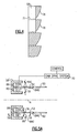
- Pivoting of a particular number of the multiple of movable cams 84 about each of their respective cam pivot 88 results in vectoring of the FVAN 42. That is, each of the multiple of movable cams 84 is selectively pivotable about the cam pivot 88 off a baseline cam axis C generally perpendicular to the cam drive ring 58' in response to a cam drive system 90.
- Various drive systems 90 may be utilized herein including, for example only, a magnetic system ( Figure 6 ) which selectively positions the movable cams 84 relative the movable baseline cam axis C. It should be understood that various other electro-mechanical drive systems may be utilized with the present invention.
- movement of the movable cams 84 toward the engine axis A is positive (+) movement while movement of the movable cams 84 away from the engine axis A is negative (-) movement.
- Movement of the movable cams 84 in the positive direction results in opening of the flap 50 from a baseline position while negative movement of the movable cams 84 results in closing of the flap 50 toward the engine axis A from a baseline position.
- rotational movement of the movable cams 84 relates to vectoring of the FVAN 42.
- the movable cam 84 at the 0 degree position moves in a positive direction toward the engine axis A such that the flap linkage 52 moves forward (e.g., +5 units; link arrow L+ ) such that the flap assembly 48 pivots about the circumferential hinge line 74 in away from the engine centerline A ( Figure 7 ).
- the movable cam 84 at the 180 degree position moves in a negative direction away from the engine axis A such that the flap linkage 52 moves aft (-5 units; link arrow L- ) such that the flap assembly 48 pivots about the circumferential hinge line 74 toward the engine centerline A ( Figure 7 ).
- the movable cam 84 at the 90 degree position and 270 degree position do not pivot and remain along the movable baseline cam axis C such that flap linkage 52 does not move (0 units; link arrow L-) and the flap assembly 48 at 90 and 270 degrees remains in the baseline position.
- the movable cam 84 at intermediate positions (0-90; 90-180; 180-270; and 27-360 degree positions) move some intermediate incrementally increasing or decreasing number of units ( Figures 5C, 5D and Figure 7B ) to define the circumference of the asymmetrically vectored FVAN 42.
- the flaps 50 at the 0 degree and 180 degree position are pivoted to a maximum "up" position, the flaps 50 at 90 degree and 270 degree position do not pivot while the flaps 50 in the lower hemi-circle progressively change in pivot position to the 90-180 degree line, while the flaps 50 in the upper hemi-circle progressively pivot ( Figure 7 ).
- the actuator system 54 communicates with an engine controller or the like to optimally adjust the position of the FVAN 42.
- other control systems including flight control systems may likewise be usable with the present invention.
- the cams may have a ramp profile.
- the cams may have a serpentine profile.
- the disclosed embodiments of this invention have been disclosed, however, one of ordinary skill in the art would recognize that certain modifications would come within the scope of this invention. It is, therefore, to be understood that within the scope of the appended claims, the invention may be practiced otherwise than as specifically described. For that reason the following claims should be studied to determine the true scope and content of this invention.
Landscapes
- Engineering & Computer Science (AREA)
- Chemical & Material Sciences (AREA)
- Combustion & Propulsion (AREA)
- Mechanical Engineering (AREA)
- General Engineering & Computer Science (AREA)
- Structures Of Non-Positive Displacement Pumps (AREA)
- Control Of Turbines (AREA)
Applications Claiming Priority (1)
| Application Number | Priority Date | Filing Date | Title |
|---|---|---|---|
| US11/672,589 US7721549B2 (en) | 2007-02-08 | 2007-02-08 | Fan variable area nozzle for a gas turbine engine fan nacelle with cam drive ring actuation system |
Publications (3)
| Publication Number | Publication Date |
|---|---|
| EP1956224A2 true EP1956224A2 (fr) | 2008-08-13 |
| EP1956224A3 EP1956224A3 (fr) | 2011-09-07 |
| EP1956224B1 EP1956224B1 (fr) | 2016-12-21 |
Family
ID=39156548
Family Applications (1)
| Application Number | Title | Priority Date | Filing Date |
|---|---|---|---|
| EP08250456.4A Active EP1956224B1 (fr) | 2007-02-08 | 2008-02-07 | Tuyère à section variable pour une nacelle de turbomoteur avec un système de mise en action à anneau d'entraînement à cames |
Country Status (3)
| Country | Link |
|---|---|
| US (1) | US7721549B2 (fr) |
| EP (1) | EP1956224B1 (fr) |
| JP (1) | JP4890478B2 (fr) |
Cited By (4)
| Publication number | Priority date | Publication date | Assignee | Title |
|---|---|---|---|---|
| EP2610460A3 (fr) * | 2011-12-30 | 2014-08-06 | United Technologies Corporation | Agencement de compresseur de turbine à gaz |
| EP2664773A3 (fr) * | 2012-05-16 | 2015-03-25 | The Boeing Company | Ensemble de volets annelés pour tuyère à géométrie variable |
| EP2800890A4 (fr) * | 2012-01-05 | 2015-09-09 | United Technologies Corp | Buse à section variable de ventilateur située dans une bifurcation d'une turbine à gaz |
| US10451004B2 (en) | 2008-06-02 | 2019-10-22 | United Technologies Corporation | Gas turbine engine with low stage count low pressure turbine |
Families Citing this family (88)
| Publication number | Priority date | Publication date | Assignee | Title |
|---|---|---|---|---|
| WO2008045082A1 (fr) * | 2006-10-12 | 2008-04-17 | United Technologies Corporation | Réduction de longueur de piste nécessaire au décollage au moyen d'une tuyère variable |
| EP2074306A1 (fr) * | 2006-10-12 | 2009-07-01 | United Technologies Corporation | Buse d'éjection à section variable intégrée à double cascade de fonctions et inverseur de poussée |
| ATE476594T1 (de) * | 2007-03-05 | 2010-08-15 | United Technologies Corp | Fandüse mit variablem querschnitt für eine gasturbinentriebwerksfangondel mit antriebsringbetätigungssystem |
| US8127529B2 (en) | 2007-03-29 | 2012-03-06 | United Technologies Corporation | Variable area fan nozzle and thrust reverser |
| US8459035B2 (en) * | 2007-07-27 | 2013-06-11 | United Technologies Corporation | Gas turbine engine with low fan pressure ratio |
| US20140157754A1 (en) | 2007-09-21 | 2014-06-12 | United Technologies Corporation | Gas turbine engine compressor arrangement |
| US9074531B2 (en) | 2008-03-05 | 2015-07-07 | United Technologies Corporation | Variable area fan nozzle fan flutter management system |
| US20090226303A1 (en) * | 2008-03-05 | 2009-09-10 | Grabowski Zbigniew M | Variable area fan nozzle fan flutter management system |
| US8695920B2 (en) | 2008-06-02 | 2014-04-15 | United Technologies Corporation | Gas turbine engine with low stage count low pressure turbine |
| US8128021B2 (en) | 2008-06-02 | 2012-03-06 | United Technologies Corporation | Engine mount system for a turbofan gas turbine engine |
| US8807477B2 (en) | 2008-06-02 | 2014-08-19 | United Technologies Corporation | Gas turbine engine compressor arrangement |
| US8800914B2 (en) | 2008-06-02 | 2014-08-12 | United Technologies Corporation | Gas turbine engine with low stage count low pressure turbine |
| US7716932B2 (en) * | 2008-07-24 | 2010-05-18 | Spirit Aerosystems, Inc. | Dilating fan duct nozzle |
| US8781737B2 (en) * | 2009-11-20 | 2014-07-15 | Qualcomm Incorporated | Spatial alignment determination for an inertial measurement unit (IMU) |
| US8443586B2 (en) * | 2009-11-24 | 2013-05-21 | United Technologies Corporation | Variable area fan nozzle bearing track |
| US20110120078A1 (en) * | 2009-11-24 | 2011-05-26 | Schwark Jr Fred W | Variable area fan nozzle track |
| US8997500B2 (en) * | 2010-02-19 | 2015-04-07 | United Technologies Corporation | Gas turbine engine oil buffering |
| US20110265490A1 (en) * | 2010-04-30 | 2011-11-03 | Kevin Samuel Klasing | Flow mixing vent system |
| US8931281B2 (en) | 2010-06-07 | 2015-01-13 | United Technologies Corporation | External flap retaining mechanism |
| US8549834B2 (en) | 2010-10-21 | 2013-10-08 | United Technologies Corporation | Gas turbine engine with variable area fan nozzle |
| US8961114B2 (en) | 2010-11-22 | 2015-02-24 | General Electric Company | Integrated variable geometry flow restrictor and heat exchanger |
| US20120301273A1 (en) * | 2011-05-24 | 2012-11-29 | Justak John F | Adjustable exhaust apparatus for a ram air turbine generating system |
| US9239012B2 (en) | 2011-06-08 | 2016-01-19 | United Technologies Corporation | Flexible support structure for a geared architecture gas turbine engine |
| US9631558B2 (en) | 2012-01-03 | 2017-04-25 | United Technologies Corporation | Geared architecture for high speed and small volume fan drive turbine |
| US9410608B2 (en) | 2011-06-08 | 2016-08-09 | United Technologies Corporation | Flexible support structure for a geared architecture gas turbine engine |
| US8613398B2 (en) | 2011-06-17 | 2013-12-24 | General Electric Company | Apparatus and methods for linear actuation of flow altering components of jet engine nozzle |
| US9021813B2 (en) | 2011-07-18 | 2015-05-05 | The Boeing Company | Cable-actuated variable area fan nozzle with elastomeric seals |
| BR102012028749B1 (pt) * | 2011-12-21 | 2022-01-18 | United Technologies Corporation | Motor de turbina a gás |
| BR112014007438B1 (pt) | 2011-12-27 | 2021-08-10 | United Technologies Corporation | Motor de turbina a gás |
| US12331691B2 (en) | 2011-12-27 | 2025-06-17 | Rtx Corporation | Gas turbine engine compressor arrangement |
| BR102012028942B1 (pt) * | 2011-12-30 | 2021-06-15 | United Technologies Corporation | Motor de turbina a gás |
| WO2013141930A1 (fr) * | 2011-12-30 | 2013-09-26 | United Technologies Corporation | Turbomoteur à faible rapport de pression de soufflante |
| WO2013141926A1 (fr) * | 2011-12-30 | 2013-09-26 | United Technologies Corporation | Tamponnage de l'huile d'un moteur à turbine |
| EP2802745A4 (fr) * | 2012-01-09 | 2015-10-21 | United Technologies Corp | Moteur de turbine à gaz doté d'une architecture à engrenages |
| US20130186058A1 (en) | 2012-01-24 | 2013-07-25 | William G. Sheridan | Geared turbomachine fan and compressor rotation |
| US9394804B2 (en) | 2012-01-24 | 2016-07-19 | Florida Institute Of Technology | Apparatus and method for rotating fluid controlling vanes in small turbine engines and other applications |
| US8863491B2 (en) * | 2012-01-31 | 2014-10-21 | United Technologies Corporation | Gas turbine engine shaft bearing configuration |
| US8935913B2 (en) * | 2012-01-31 | 2015-01-20 | United Technologies Corporation | Geared turbofan gas turbine engine architecture |
| US9140137B2 (en) * | 2012-01-31 | 2015-09-22 | United Technologies Corporation | Gas turbine engine mid turbine frame bearing support |
| US20130192265A1 (en) * | 2012-01-31 | 2013-08-01 | Frederick M. Schwarz | Gas turbine engine with high speed low pressure turbine section and bearing support features |
| US20130192191A1 (en) | 2012-01-31 | 2013-08-01 | Frederick M. Schwarz | Gas turbine engine with high speed low pressure turbine section and bearing support features |
| US10240526B2 (en) | 2012-01-31 | 2019-03-26 | United Technologies Corporation | Gas turbine engine with high speed low pressure turbine section |
| US10287914B2 (en) | 2012-01-31 | 2019-05-14 | United Technologies Corporation | Gas turbine engine with high speed low pressure turbine section and bearing support features |
| US20160130949A1 (en) | 2012-01-31 | 2016-05-12 | United Technologies Corporation | Low noise turbine for geared turbofan engine |
| US8246292B1 (en) * | 2012-01-31 | 2012-08-21 | United Technologies Corporation | Low noise turbine for geared turbofan engine |
| US9845726B2 (en) | 2012-01-31 | 2017-12-19 | United Technologies Corporation | Gas turbine engine with high speed low pressure turbine section |
| US20150345426A1 (en) | 2012-01-31 | 2015-12-03 | United Technologies Corporation | Geared turbofan gas turbine engine architecture |
| US20130192196A1 (en) | 2012-01-31 | 2013-08-01 | Gabriel L. Suciu | Gas turbine engine with high speed low pressure turbine section |
| US9816442B2 (en) | 2012-01-31 | 2017-11-14 | United Technologies Corporation | Gas turbine engine with high speed low pressure turbine section |
| US9611859B2 (en) | 2012-01-31 | 2017-04-04 | United Technologies Corporation | Gas turbine engine with high speed low pressure turbine section and bearing support features |
| US20130192258A1 (en) * | 2012-01-31 | 2013-08-01 | United Technologies Corporation | Geared turbofan gas turbine engine architecture |
| US20130192263A1 (en) * | 2012-01-31 | 2013-08-01 | Gabriel L. Suciu | Gas turbine engine with high speed low pressure turbine section |
| US9222417B2 (en) | 2012-01-31 | 2015-12-29 | United Technologies Corporation | Geared turbofan gas turbine engine architecture |
| US20130192266A1 (en) | 2012-01-31 | 2013-08-01 | United Technologies Corporation | Geared turbofan gas turbine engine architecture |
| US10400629B2 (en) | 2012-01-31 | 2019-09-03 | United Technologies Corporation | Gas turbine engine shaft bearing configuration |
| US8887487B2 (en) | 2012-01-31 | 2014-11-18 | United Technologies Corporation | Geared turbofan gas turbine engine architecture |
| US10309232B2 (en) * | 2012-02-29 | 2019-06-04 | United Technologies Corporation | Gas turbine engine with stage dependent material selection for blades and disk |
| FR2988434B1 (fr) * | 2012-03-20 | 2016-02-05 | Aircelle Sa | Cone d'ejection des gaz pour turboreacteurs d'aeronefs |
| US10138809B2 (en) | 2012-04-02 | 2018-11-27 | United Technologies Corporation | Geared turbofan engine with a high ratio of thrust to turbine volume |
| US10125693B2 (en) | 2012-04-02 | 2018-11-13 | United Technologies Corporation | Geared turbofan engine with power density range |
| FR2989429B1 (fr) * | 2012-04-17 | 2014-05-16 | Airbus Operations Sas | Dispositif de commande d'une tuyere a section variable d'un aeronef |
| US8572943B1 (en) | 2012-05-31 | 2013-11-05 | United Technologies Corporation | Fundamental gear system architecture |
| US8756908B2 (en) | 2012-05-31 | 2014-06-24 | United Technologies Corporation | Fundamental gear system architecture |
| US20150308351A1 (en) | 2012-05-31 | 2015-10-29 | United Technologies Corporation | Fundamental gear system architecture |
| US9249731B2 (en) * | 2012-06-05 | 2016-02-02 | United Technologies Corporation | Nacelle bifurcation for gas turbine engine |
| US20140090388A1 (en) * | 2012-09-28 | 2014-04-03 | United Technologies Corporation | Off-take power ratio |
| US9624834B2 (en) | 2012-09-28 | 2017-04-18 | United Technologies Corporation | Low noise compressor rotor for geared turbofan engine |
| US20160138474A1 (en) | 2012-09-28 | 2016-05-19 | United Technologies Corporation | Low noise compressor rotor for geared turbofan engine |
| US9989009B2 (en) * | 2012-10-31 | 2018-06-05 | The Boeing Company | Methods and apparatus for sealing variable area fan nozzles of jet engines |
| US20140130479A1 (en) * | 2012-11-14 | 2014-05-15 | United Technologies Corporation | Gas Turbine Engine With Mount for Low Pressure Turbine Section |
| US10563592B2 (en) * | 2012-12-14 | 2020-02-18 | United Technologies Corporation | Turbo compressor for bleed air |
| US9261046B2 (en) * | 2013-01-21 | 2016-02-16 | Lockheed Martin Corporation | Gas turbine exhaust noise reduction |
| US9926850B2 (en) * | 2013-02-11 | 2018-03-27 | United Technologies Corporation | Compound star gear system with rolling element bearings |
| US10400621B2 (en) | 2013-03-04 | 2019-09-03 | United Technologies Corporation | Pivot door thrust reverser with variable area nozzle |
| US10605172B2 (en) | 2013-03-14 | 2020-03-31 | United Technologies Corporation | Low noise turbine for geared gas turbine engine |
| US11719161B2 (en) | 2013-03-14 | 2023-08-08 | Raytheon Technologies Corporation | Low noise turbine for geared gas turbine engine |
| US10724479B2 (en) | 2013-03-15 | 2020-07-28 | United Technologies Corporation | Thrust efficient turbofan engine |
| US9624827B2 (en) | 2013-03-15 | 2017-04-18 | United Technologies Corporation | Thrust efficient turbofan engine |
| US9581145B2 (en) * | 2013-05-14 | 2017-02-28 | The Boeing Company | Shape memory alloy actuation system for variable area fan nozzle |
| US9650991B2 (en) | 2013-06-27 | 2017-05-16 | The Boeing Company | Pivoting ring petal actuation for variable area fan nozzle |
| FR3010387B1 (fr) * | 2013-09-10 | 2015-10-09 | Airbus Operations Sas | Aeronef comprenant un dispositif de commande d'une tuyere a section variable alimente par deux alimentations electriques independantes |
| US9488130B2 (en) | 2013-10-17 | 2016-11-08 | Honeywell International Inc. | Variable area fan nozzle systems with improved drive couplings |
| US9863367B2 (en) * | 2013-11-01 | 2018-01-09 | The Boeing Company | Fan nozzle drive systems that lock thrust reversers |
| CA2915233C (fr) * | 2015-01-08 | 2018-12-04 | David A. Topol | Rotor de compresseur peu bruyant pour reacteur a reducteur |
| US10422301B2 (en) * | 2015-07-13 | 2019-09-24 | The Boeing Company | Telescoping electrical cable |
| PL417832A1 (pl) | 2016-07-04 | 2018-01-15 | General Electric Company | Zespół rozszerzenia kielichowego, zwłaszcza do dyszy i sposób jego rozkładania oraz silnik turbowentylatorowy zawierający ten zespół |
| CA3034776A1 (fr) * | 2016-08-25 | 2018-03-01 | Jetoptera, Inc. | Propulseur a geometrie variable |
| US11781506B2 (en) | 2020-06-03 | 2023-10-10 | Rtx Corporation | Splitter and guide vane arrangement for gas turbine engines |
Citations (1)
| Publication number | Priority date | Publication date | Assignee | Title |
|---|---|---|---|---|
| WO2004104377A2 (fr) | 2003-05-09 | 2004-12-02 | The Nordam Group, Inc. | Tuyere d'echappement rotative et reglable |
Family Cites Families (35)
| Publication number | Priority date | Publication date | Assignee | Title |
|---|---|---|---|---|
| GB1125268A (en) * | 1967-01-12 | 1968-08-28 | Rolls Royce | Thrust spoiling and silencing in a gas turbine engine |
| US4132068A (en) * | 1975-04-30 | 1979-01-02 | The United States Of America As Represented By The United States National Aeronautics And Space Administration | Variable area exhaust nozzle |
| US4068469A (en) * | 1975-05-29 | 1978-01-17 | The United States Of America As Represented By The Administrator Of The National Aeronautics And Space Administration | Variable thrust nozzle for quiet turbofan engine and method of operating same |
| GB2043786B (en) * | 1979-03-10 | 1983-01-12 | Rolls Royce | Gas turbine engine power plant |
| US4409788A (en) * | 1979-04-23 | 1983-10-18 | General Electric Company | Actuation system for use on a gas turbine engine |
| US5107675A (en) * | 1983-03-18 | 1992-04-28 | Rolls-Royce Limited | Gas turbine engine |
| US5201800A (en) * | 1990-02-26 | 1993-04-13 | General Electric Company | Method for discharging combustion gases from an exhaust nozzle |
| US5082182A (en) * | 1990-08-23 | 1992-01-21 | United Technologies Corporation | Thrust vectoring exhaust nozzle |
| US5261605A (en) * | 1990-08-23 | 1993-11-16 | United Technologies Corporation | Axisymmetric nozzle with gimbled unison ring |
| US5120005A (en) * | 1990-09-14 | 1992-06-09 | General Electric Company | Exhaust flap speedbrake |
| US5150839A (en) * | 1991-03-14 | 1992-09-29 | General Electric Company | Nozzle load management |
| EP0723075B1 (fr) * | 1991-05-16 | 2001-11-21 | General Electric Company | Ecran thermique pour tuyère axisymétrique à poussée dirigeable |
| ES2075782B1 (es) * | 1992-02-20 | 1998-03-16 | Sener Ing & Sist | Tobera orientable de geometria variable para turbinas de gas. |
| FR2698409B1 (fr) * | 1992-11-25 | 1994-12-23 | Snecma | Tuyère d'éjection de turboréacteur. |
| US5833140A (en) * | 1996-12-12 | 1998-11-10 | United Technologies Corporation | Variable geometry exhaust nozzle for a turbine engine |
| ES2136528B1 (es) * | 1996-12-26 | 2000-05-01 | Sener Ing & Sist | Perfeccionamientos en toberas axisimetricas de geometria variable y orientacion del flujo destinadasa propulsores de turbina de gas |
| US5779152A (en) * | 1997-01-16 | 1998-07-14 | General Electric Company | Coordinated vectoring exhaust nozzle with scissors linkage |
| ES2156350T3 (es) * | 1997-01-17 | 2001-06-16 | Turbo Propulsores Ind | Disposicion de petalos divergentes para tobera convergente-divergente de motor de aviacion. |
| DE69725432T2 (de) * | 1997-06-16 | 2004-08-19 | Industria De Turbo Propulsores S.A., Zamudio | Befestigungsvorrichtung für eine divergierende Master-Düsenklappe einer Schubüse mit veränderlicher Geometrie |
| US6212877B1 (en) * | 1998-09-04 | 2001-04-10 | General Electric Company | Vectoring ring support and actuation mechanism for axisymmetric vectoring nozzle with a universal joint |
| FR2792367B1 (fr) * | 1999-04-15 | 2002-04-26 | Snecma | Tuyere d'ejection axisymetrique, convergente divergente a orientation par un anneau guide |
| US6318070B1 (en) * | 2000-03-03 | 2001-11-20 | United Technologies Corporation | Variable area nozzle for gas turbine engines driven by shape memory alloy actuators |
| US6439840B1 (en) * | 2000-11-30 | 2002-08-27 | Pratt & Whitney Canada Corp. | Bypass duct fan noise reduction assembly |
| US6640537B2 (en) * | 2000-12-18 | 2003-11-04 | Pratt & Whitney Canada Corp. | Aero-engine exhaust jet noise reduction assembly |
| GB0105349D0 (en) * | 2001-03-03 | 2001-04-18 | Rolls Royce Plc | Gas turbine engine exhaust nozzle |
| US6415599B1 (en) * | 2001-05-11 | 2002-07-09 | General Electric Company | Engine interface for axisymmetric vectoring nozzle |
| US6505706B2 (en) * | 2001-06-14 | 2003-01-14 | Pratt & Whitney Canada Corp. | Exhaust flow guide for jet noise reduction |
| US6748744B2 (en) * | 2001-11-21 | 2004-06-15 | Pratt & Whitney Canada Corp. | Method and apparatus for the engine control of output shaft speed |
| US6543224B1 (en) * | 2002-01-29 | 2003-04-08 | United Technologies Corporation | System and method for controlling shape memory alloy actuators |
| US6718752B2 (en) * | 2002-05-29 | 2004-04-13 | The Boeing Company | Deployable segmented exhaust nozzle for a jet engine |
| US7055329B2 (en) * | 2003-03-31 | 2006-06-06 | General Electric Company | Method and apparatus for noise attenuation for gas turbine engines using at least one synthetic jet actuator for injecting air |
| US7043898B2 (en) * | 2003-06-23 | 2006-05-16 | Pratt & Whitney Canada Corp. | Combined exhaust duct and mixer for a gas turbine engine |
| FR2857414B1 (fr) * | 2003-07-08 | 2007-06-08 | Snecma Moteurs | Volet souple de tuyere a section variable de turbomachine |
| US7093793B2 (en) * | 2003-08-29 | 2006-08-22 | The Nordam Group, Inc. | Variable cam exhaust nozzle |
| US7093423B2 (en) * | 2004-01-20 | 2006-08-22 | General Electric Company | Methods and apparatus for operating gas turbine engines |
-
2007
- 2007-02-08 US US11/672,589 patent/US7721549B2/en active Active
-
2008
- 2008-02-06 JP JP2008025851A patent/JP4890478B2/ja not_active Expired - Fee Related
- 2008-02-07 EP EP08250456.4A patent/EP1956224B1/fr active Active
Patent Citations (1)
| Publication number | Priority date | Publication date | Assignee | Title |
|---|---|---|---|---|
| WO2004104377A2 (fr) | 2003-05-09 | 2004-12-02 | The Nordam Group, Inc. | Tuyere d'echappement rotative et reglable |
Cited By (13)
| Publication number | Priority date | Publication date | Assignee | Title |
|---|---|---|---|---|
| US10451004B2 (en) | 2008-06-02 | 2019-10-22 | United Technologies Corporation | Gas turbine engine with low stage count low pressure turbine |
| US12179929B2 (en) | 2008-06-02 | 2024-12-31 | Rtx Corporation | Engine mount system for a gas turbine engine |
| US11731773B2 (en) | 2008-06-02 | 2023-08-22 | Raytheon Technologies Corporation | Engine mount system for a gas turbine engine |
| US11286883B2 (en) | 2008-06-02 | 2022-03-29 | Raytheon Technologies Corporation | Gas turbine engine with low stage count low pressure turbine and engine mounting arrangement |
| US9885313B2 (en) | 2009-03-17 | 2018-02-06 | United Technologes Corporation | Gas turbine engine bifurcation located fan variable area nozzle |
| US10989143B2 (en) | 2009-03-17 | 2021-04-27 | Raytheon Technologies Corporation | Gas turbine engine bifurcation located fan variable area nozzle |
| US11391240B2 (en) | 2009-03-17 | 2022-07-19 | Raytheon Technologies Corporation | Gas turbine engine bifurcation located fan variable area nozzle |
| EP2610460A3 (fr) * | 2011-12-30 | 2014-08-06 | United Technologies Corporation | Agencement de compresseur de turbine à gaz |
| EP2944790A1 (fr) * | 2011-12-30 | 2015-11-18 | United Technologies Corporation | Agencement de compresseur de turbine à gaz |
| EP2944791A1 (fr) * | 2012-01-05 | 2015-11-18 | United Technologies Corporation | Buse à section variable de ventilateur située dans une bifurcation d'une turbine à gaz |
| EP2800890A4 (fr) * | 2012-01-05 | 2015-09-09 | United Technologies Corp | Buse à section variable de ventilateur située dans une bifurcation d'une turbine à gaz |
| US9091230B2 (en) | 2012-05-16 | 2015-07-28 | The Boeing Company | Linked ring petal actuation for variable area fan nozzle |
| EP2664773A3 (fr) * | 2012-05-16 | 2015-03-25 | The Boeing Company | Ensemble de volets annelés pour tuyère à géométrie variable |
Also Published As
| Publication number | Publication date |
|---|---|
| JP4890478B2 (ja) | 2012-03-07 |
| US7721549B2 (en) | 2010-05-25 |
| EP1956224B1 (fr) | 2016-12-21 |
| US20080190095A1 (en) | 2008-08-14 |
| EP1956224A3 (fr) | 2011-09-07 |
| JP2008196489A (ja) | 2008-08-28 |
Similar Documents
| Publication | Publication Date | Title |
|---|---|---|
| EP1956224B1 (fr) | Tuyère à section variable pour une nacelle de turbomoteur avec un système de mise en action à anneau d'entraînement à cames | |
| US10519898B2 (en) | Fan variable area nozzle for a gas turbine engine fan nacelle with sliding actuation system | |
| US8316646B2 (en) | Fan variable area nozzle for a gas turbine engine fan nacelle with drive ring actuation system | |
| US8347633B2 (en) | Gas turbine engine with variable geometry fan exit guide vane system | |
| US8443586B2 (en) | Variable area fan nozzle bearing track | |
| US8365515B2 (en) | Gas turbine engine with fan variable area nozzle, nacelle assembly and method of varying area of a fan nozzle | |
| EP2074321B1 (fr) | Tuyere a section variable a soufflante avec structure adaptative et procede de varier la section de sortie de la tuyere du flux secondaire d'une turbine a gaz | |
| US20110120078A1 (en) | Variable area fan nozzle track | |
| EP2028359A2 (fr) | Moteur à turbine à gaz doté d'une tuyère de ventilateur à surface variable mobile axialement | |
| US20120233981A1 (en) | Gas turbine engine with low fan pressure ratio | |
| US20120222398A1 (en) | Gas turbine engine with geared architecture | |
| US8256225B2 (en) | Gas turbine engine with a variable exit area fan nozzle, nacelle assembly of such a engine, and corresponding operating method | |
| EP2069629A1 (fr) | Buse à section variable d'un ventilateur de turbine à gaz équipée d'un système à pièces rapportées pivotantes | |
| US20100050595A1 (en) | Gas turbine engine with axial movable fan variable area nozzle |
Legal Events
| Date | Code | Title | Description |
|---|---|---|---|
| PUAI | Public reference made under article 153(3) epc to a published international application that has entered the european phase |
Free format text: ORIGINAL CODE: 0009012 |
|
| AK | Designated contracting states |
Kind code of ref document: A2 Designated state(s): AT BE BG CH CY CZ DE DK EE ES FI FR GB GR HR HU IE IS IT LI LT LU LV MC MT NL NO PL PT RO SE SI SK TR |
|
| AX | Request for extension of the european patent |
Extension state: AL BA MK RS |
|
| REG | Reference to a national code |
Ref country code: DE Ref legal event code: R079 Ref document number: 602008047963 Country of ref document: DE Free format text: PREVIOUS MAIN CLASS: F02K0001700000 Ipc: F02K0001000000 |
|
| PUAL | Search report despatched |
Free format text: ORIGINAL CODE: 0009013 |
|
| AK | Designated contracting states |
Kind code of ref document: A3 Designated state(s): AT BE BG CH CY CZ DE DK EE ES FI FR GB GR HR HU IE IS IT LI LT LU LV MC MT NL NO PL PT RO SE SI SK TR |
|
| AX | Request for extension of the european patent |
Extension state: AL BA MK RS |
|
| RIC1 | Information provided on ipc code assigned before grant |
Ipc: F02K 1/12 20060101ALI20110729BHEP Ipc: F02K 1/00 20060101AFI20110729BHEP |
|
| 17P | Request for examination filed |
Effective date: 20120306 |
|
| AKX | Designation fees paid |
Designated state(s): DE GB |
|
| 17Q | First examination report despatched |
Effective date: 20121217 |
|
| GRAP | Despatch of communication of intention to grant a patent |
Free format text: ORIGINAL CODE: EPIDOSNIGR1 |
|
| INTG | Intention to grant announced |
Effective date: 20160916 |
|
| RAP1 | Party data changed (applicant data changed or rights of an application transferred) |
Owner name: UNITED TECHNOLOGIES CORPORATION |
|
| GRAS | Grant fee paid |
Free format text: ORIGINAL CODE: EPIDOSNIGR3 |
|
| GRAA | (expected) grant |
Free format text: ORIGINAL CODE: 0009210 |
|
| AK | Designated contracting states |
Kind code of ref document: B1 Designated state(s): DE GB |
|
| REG | Reference to a national code |
Ref country code: GB Ref legal event code: FG4D |
|
| REG | Reference to a national code |
Ref country code: DE Ref legal event code: R096 Ref document number: 602008047963 Country of ref document: DE |
|
| REG | Reference to a national code |
Ref country code: DE Ref legal event code: R082 Ref document number: 602008047963 Country of ref document: DE Representative=s name: SCHMITT-NILSON SCHRAUD WAIBEL WOHLFROM PATENTA, DE |
|
| REG | Reference to a national code |
Ref country code: DE Ref legal event code: R097 Ref document number: 602008047963 Country of ref document: DE |
|
| PLBE | No opposition filed within time limit |
Free format text: ORIGINAL CODE: 0009261 |
|
| STAA | Information on the status of an ep patent application or granted ep patent |
Free format text: STATUS: NO OPPOSITION FILED WITHIN TIME LIMIT |
|
| 26N | No opposition filed |
Effective date: 20170922 |
|
| REG | Reference to a national code |
Ref country code: DE Ref legal event code: R081 Ref document number: 602008047963 Country of ref document: DE Owner name: RAYTHEON TECHNOLOGIES CORPORATION (N.D.GES.D.S, US Free format text: FORMER OWNER: UNITED TECHNOLOGIES CORPORATION, FARMINGTON, CONN., US Ref country code: DE Ref legal event code: R081 Ref document number: 602008047963 Country of ref document: DE Owner name: RTX CORPORATION (N.D.GES.D. STAATES DELAWARE),, US Free format text: FORMER OWNER: UNITED TECHNOLOGIES CORPORATION, FARMINGTON, CONN., US |
|
| P01 | Opt-out of the competence of the unified patent court (upc) registered |
Effective date: 20230519 |
|
| REG | Reference to a national code |
Ref country code: DE Ref legal event code: R081 Ref document number: 602008047963 Country of ref document: DE Owner name: RTX CORPORATION (N.D.GES.D. STAATES DELAWARE),, US Free format text: FORMER OWNER: RAYTHEON TECHNOLOGIES CORPORATION (N.D.GES.D.STAATES DELAWARE), ARLINGTON, VA, US |
|
| PGFP | Annual fee paid to national office [announced via postgrant information from national office to epo] |
Ref country code: GB Payment date: 20260121 Year of fee payment: 19 |
|
| PGFP | Annual fee paid to national office [announced via postgrant information from national office to epo] |
Ref country code: DE Payment date: 20260121 Year of fee payment: 19 |