EP1956257B1 - Dispositif de palier à roulement - Google Patents
Dispositif de palier à roulement Download PDFInfo
- Publication number
- EP1956257B1 EP1956257B1 EP08290048A EP08290048A EP1956257B1 EP 1956257 B1 EP1956257 B1 EP 1956257B1 EP 08290048 A EP08290048 A EP 08290048A EP 08290048 A EP08290048 A EP 08290048A EP 1956257 B1 EP1956257 B1 EP 1956257B1
- Authority
- EP
- European Patent Office
- Prior art keywords
- ring
- material comprises
- rings
- sand
- additional
- Prior art date
- Legal status (The legal status is an assumption and is not a legal conclusion. Google has not performed a legal analysis and makes no representation as to the accuracy of the status listed.)
- Not-in-force
Links
Images


Classifications
-
- F—MECHANICAL ENGINEERING; LIGHTING; HEATING; WEAPONS; BLASTING
- F16—ENGINEERING ELEMENTS AND UNITS; GENERAL MEASURES FOR PRODUCING AND MAINTAINING EFFECTIVE FUNCTIONING OF MACHINES OR INSTALLATIONS; THERMAL INSULATION IN GENERAL
- F16C—SHAFTS; FLEXIBLE SHAFTS; ELEMENTS OR CRANKSHAFT MECHANISMS; ROTARY BODIES OTHER THAN GEARING ELEMENTS; BEARINGS
- F16C35/00—Rigid support of bearing units; Housings, e.g. caps, covers
-
- F—MECHANICAL ENGINEERING; LIGHTING; HEATING; WEAPONS; BLASTING
- F16—ENGINEERING ELEMENTS AND UNITS; GENERAL MEASURES FOR PRODUCING AND MAINTAINING EFFECTIVE FUNCTIONING OF MACHINES OR INSTALLATIONS; THERMAL INSULATION IN GENERAL
- F16C—SHAFTS; FLEXIBLE SHAFTS; ELEMENTS OR CRANKSHAFT MECHANISMS; ROTARY BODIES OTHER THAN GEARING ELEMENTS; BEARINGS
- F16C19/00—Bearings with rolling contact, for exclusively rotary movement
- F16C19/02—Bearings with rolling contact, for exclusively rotary movement with bearing balls essentially of the same size in one or more circular rows
- F16C19/14—Bearings with rolling contact, for exclusively rotary movement with bearing balls essentially of the same size in one or more circular rows for both radial and axial load
- F16C19/18—Bearings with rolling contact, for exclusively rotary movement with bearing balls essentially of the same size in one or more circular rows for both radial and axial load with two or more rows of balls
- F16C19/181—Bearings with rolling contact, for exclusively rotary movement with bearing balls essentially of the same size in one or more circular rows for both radial and axial load with two or more rows of balls with angular contact
- F16C19/183—Bearings with rolling contact, for exclusively rotary movement with bearing balls essentially of the same size in one or more circular rows for both radial and axial load with two or more rows of balls with angular contact with two rows at opposite angles
- F16C19/184—Bearings with rolling contact, for exclusively rotary movement with bearing balls essentially of the same size in one or more circular rows for both radial and axial load with two or more rows of balls with angular contact with two rows at opposite angles in O-arrangement
-
- F—MECHANICAL ENGINEERING; LIGHTING; HEATING; WEAPONS; BLASTING
- F16—ENGINEERING ELEMENTS AND UNITS; GENERAL MEASURES FOR PRODUCING AND MAINTAINING EFFECTIVE FUNCTIONING OF MACHINES OR INSTALLATIONS; THERMAL INSULATION IN GENERAL
- F16C—SHAFTS; FLEXIBLE SHAFTS; ELEMENTS OR CRANKSHAFT MECHANISMS; ROTARY BODIES OTHER THAN GEARING ELEMENTS; BEARINGS
- F16C27/00—Elastic or yielding bearings or bearing supports, for exclusively rotary movement
- F16C27/06—Elastic or yielding bearings or bearing supports, for exclusively rotary movement by means of parts of rubber or like materials
- F16C27/066—Ball or roller bearings
-
- F—MECHANICAL ENGINEERING; LIGHTING; HEATING; WEAPONS; BLASTING
- F16—ENGINEERING ELEMENTS AND UNITS; GENERAL MEASURES FOR PRODUCING AND MAINTAINING EFFECTIVE FUNCTIONING OF MACHINES OR INSTALLATIONS; THERMAL INSULATION IN GENERAL
- F16C—SHAFTS; FLEXIBLE SHAFTS; ELEMENTS OR CRANKSHAFT MECHANISMS; ROTARY BODIES OTHER THAN GEARING ELEMENTS; BEARINGS
- F16C33/00—Parts of bearings; Special methods for making bearings or parts thereof
- F16C33/30—Parts of ball or roller bearings
- F16C33/58—Raceways; Race rings
- F16C33/60—Raceways; Race rings divided or split, e.g. comprising two juxtaposed rings
- F16C33/61—Raceways; Race rings divided or split, e.g. comprising two juxtaposed rings formed by wires
-
- F—MECHANICAL ENGINEERING; LIGHTING; HEATING; WEAPONS; BLASTING
- F16—ENGINEERING ELEMENTS AND UNITS; GENERAL MEASURES FOR PRODUCING AND MAINTAINING EFFECTIVE FUNCTIONING OF MACHINES OR INSTALLATIONS; THERMAL INSULATION IN GENERAL
- F16C—SHAFTS; FLEXIBLE SHAFTS; ELEMENTS OR CRANKSHAFT MECHANISMS; ROTARY BODIES OTHER THAN GEARING ELEMENTS; BEARINGS
- F16C33/00—Parts of bearings; Special methods for making bearings or parts thereof
- F16C33/30—Parts of ball or roller bearings
- F16C33/58—Raceways; Race rings
- F16C33/62—Selection of substances
-
- F—MECHANICAL ENGINEERING; LIGHTING; HEATING; WEAPONS; BLASTING
- F16—ENGINEERING ELEMENTS AND UNITS; GENERAL MEASURES FOR PRODUCING AND MAINTAINING EFFECTIVE FUNCTIONING OF MACHINES OR INSTALLATIONS; THERMAL INSULATION IN GENERAL
- F16C—SHAFTS; FLEXIBLE SHAFTS; ELEMENTS OR CRANKSHAFT MECHANISMS; ROTARY BODIES OTHER THAN GEARING ELEMENTS; BEARINGS
- F16C35/00—Rigid support of bearing units; Housings, e.g. caps, covers
- F16C35/04—Rigid support of bearing units; Housings, e.g. caps, covers in the case of ball or roller bearings
-
- F—MECHANICAL ENGINEERING; LIGHTING; HEATING; WEAPONS; BLASTING
- F16—ENGINEERING ELEMENTS AND UNITS; GENERAL MEASURES FOR PRODUCING AND MAINTAINING EFFECTIVE FUNCTIONING OF MACHINES OR INSTALLATIONS; THERMAL INSULATION IN GENERAL
- F16F—SPRINGS; SHOCK-ABSORBERS; MEANS FOR DAMPING VIBRATION
- F16F1/00—Springs
- F16F1/02—Springs made of steel or other material having low internal friction; Wound, torsion, leaf, cup, ring or the like springs, the material of the spring not being relevant
-
- F—MECHANICAL ENGINEERING; LIGHTING; HEATING; WEAPONS; BLASTING
- F16—ENGINEERING ELEMENTS AND UNITS; GENERAL MEASURES FOR PRODUCING AND MAINTAINING EFFECTIVE FUNCTIONING OF MACHINES OR INSTALLATIONS; THERMAL INSULATION IN GENERAL
- F16F—SPRINGS; SHOCK-ABSORBERS; MEANS FOR DAMPING VIBRATION
- F16F7/00—Vibration-dampers; Shock-absorbers
- F16F7/01—Vibration-dampers; Shock-absorbers using friction between loose particles, e.g. sand
-
- F—MECHANICAL ENGINEERING; LIGHTING; HEATING; WEAPONS; BLASTING
- F16—ENGINEERING ELEMENTS AND UNITS; GENERAL MEASURES FOR PRODUCING AND MAINTAINING EFFECTIVE FUNCTIONING OF MACHINES OR INSTALLATIONS; THERMAL INSULATION IN GENERAL
- F16C—SHAFTS; FLEXIBLE SHAFTS; ELEMENTS OR CRANKSHAFT MECHANISMS; ROTARY BODIES OTHER THAN GEARING ELEMENTS; BEARINGS
- F16C2300/00—Application independent of particular apparatuses
- F16C2300/10—Application independent of particular apparatuses related to size
- F16C2300/14—Large applications, e.g. bearings having an inner diameter exceeding 500 mm
-
- F—MECHANICAL ENGINEERING; LIGHTING; HEATING; WEAPONS; BLASTING
- F16—ENGINEERING ELEMENTS AND UNITS; GENERAL MEASURES FOR PRODUCING AND MAINTAINING EFFECTIVE FUNCTIONING OF MACHINES OR INSTALLATIONS; THERMAL INSULATION IN GENERAL
- F16C—SHAFTS; FLEXIBLE SHAFTS; ELEMENTS OR CRANKSHAFT MECHANISMS; ROTARY BODIES OTHER THAN GEARING ELEMENTS; BEARINGS
- F16C2316/00—Apparatus in health or amusement
- F16C2316/10—Apparatus in health or amusement in medical appliances, e.g. in diagnosis, dentistry, instruments, prostheses, medical imaging appliances
-
- F—MECHANICAL ENGINEERING; LIGHTING; HEATING; WEAPONS; BLASTING
- F16—ENGINEERING ELEMENTS AND UNITS; GENERAL MEASURES FOR PRODUCING AND MAINTAINING EFFECTIVE FUNCTIONING OF MACHINES OR INSTALLATIONS; THERMAL INSULATION IN GENERAL
- F16C—SHAFTS; FLEXIBLE SHAFTS; ELEMENTS OR CRANKSHAFT MECHANISMS; ROTARY BODIES OTHER THAN GEARING ELEMENTS; BEARINGS
- F16C41/00—Other accessories, e.g. devices integrated in the bearing not relating to the bearing function as such
- F16C41/004—Electro-dynamic machines, e.g. motors, generators, actuators
Definitions
- the present invention relates to the field of rolling bearings used in particular in medical imaging devices such as scanners.
- Such bearings generally have a large diameter, of the order of one meter, and rotate at a speed of a few hundred revolutions / minute, for example between 200 and 300.
- the invention aims to remedy these drawbacks.
- the invention proposes a rolling bearing with a very high vibration damping effect, in particular rolling vibrations.
- the rolling bearing device comprises an outer ring whose main body comprises one or more elements, an inner ring whose main body comprises one or more elements, the outer and inner rings each comprising at least one integrated raceway or reported for rolling elements arranged between said rings in contact with the raceways.
- At least one of the elements forming the main body above comprises a metallic material having a vibration damping coefficient greater than 0.0001.
- the vibration damping coefficient is greater than or equal to 0.001. More preferably, the vibration damping coefficient is greater than or equal to 0.01.
- Vibration damping coefficient means the ratio between the acoustic energy emitted by a sample of the material in question and the vibratory energy received by said sample. The vibration damping coefficient is therefore the quotient of an energy by an energy and is expressed without unity.
- the damping of a wall or a material characterizes its ability to dissipate a greater or lesser amount of vibratory energy when it is set in motion by acoustic or mechanical excitation.
- a wall with little or no damping will have great ability to emit acoustic radiation in case of excitation. Conversely, a very damp wall stops vibrating as soon as you remove the excitement.
- the damping capacity of a material is characterized by its loss factor ⁇ . It can also depend on the Young's modulus (E) expressed in daN / cm 2 .
- ⁇ W ⁇ 1 ⁇ oss / 2 * PI * W ⁇ 2 Wloss 2 ⁇ ⁇ ⁇ W ⁇ 2
- said material comprises cast iron, preferably gray cast iron.
- the font may include lamellar or nodular graphite.
- GG40 cast iron it is possible to use GG40 cast iron.
- the material comprises a manganese-copper alloy, for example Sonostron®.
- the manganese-copper alloy may be of the Z9225, Z9240, Z8861 or Z9000 type.
- the mass percentage of manganese may be between 50 and 54%.
- the mass percentage of copper may be between 38 and 42%.
- the mass percentage of aluminum may be between 3 and 5%.
- the mass percentage of iron may be between 2 and 4%.
- the mass percentage of nickel may be between 0.5 and 2%. Any other constituents being present in individual mass percentages of less than 1%.
- the material comprises a copper-aluminum-manganese alloy with a memory effect, for example of the maxidamp® type.
- At least one ring member further comprises an additional damping material disposed in one or more hollow portions in said member.
- the additional material may comprise particles or molecules whose friction caused by the vibrations of the surrounding material transforms, at least in part, the vibratory energy into heat.
- the additional material may include sand.
- the sand may comprise at least a portion of the sand used in the core of the foundry mold for forming the hollow portion of the ring member to contain the additional material, the foundry sand being left voluntarily after cooling the metal of the the ring element.
- the sand may be at least in part sand reported in the hollow portion of the ring member.
- the additional material comprises a polymer, for example a polyurethane foam.
- the additional material comprises a metal foam.
- the additional material comprises a silicone paste introduced through at least one hole in the hollow portion after removal of the foundry sand.
- the additional material comprises cement.
- the cement may or may not be loaded with another material, for example a material promoting the damping of acoustic waves, for example an additive in fibrous or granular form.
- the additional material comprises lead.
- the device may comprise a motor that rotates one ring relative to the other.
- the device may comprise a system for detecting the angular displacement of the rotating ring.
- the rolling bearing device comprises an outer ring provided with one or more elements, an inner ring provided with one or more elements, the outer and inner rings each comprising at least one integrated raceway. or reported, for rolling elements disposed between said rings in contact with the raceways, at least one ring member further comprising an additional damping material disposed in one or more hollow portions in said element.
- Said element may be annular and / or metallic.
- Said element may comprise a ring-shaped half-ring.
- the races of at least one of the outer and inner rings are reported, they can advantageously be made in the form of reported annular son, made for example of treated steel.
- These annular son advantageously have a substantially circular cross section, with the exception of a concavity forming a raceway.
- the races of at least one of the outer and inner rings are integrated, they can, for example, be machined directly on said bearing ring so as to form a rolling path for rolling elements, for example of toroidal shape when balls are used as rolling elements.
- a method of manufacturing at least one rolling bearing ring member may include the steps of forming a ring member by reserving at least one hollow portion in said ring member, said hollow portion being filled with a filler material.
- the mold is filled with a metal alloy to form said ring member.
- the holes communicating the cell with the outside can then be closed by leaving the filling material, for example foundry sand, or removing the foundry filler material and replacing it with a material. damper.
- a medical imaging apparatus may include a rolling bearing as described above, disposed between a non-rotating portion and a rotating portion.
- the rotating part can support sensors.
- the apparatus may be of the scanner or nuclear magnetic resonance apparatus type.
- the operating noise of the device is considerably reduced.
- the mass of the rotating part is not substantially modified. Reducing operating noise increases comfort and reduces fatigue for the patient and medical staff.
- the rolling bearing 1 comprises an outer ring 2, an inner ring 3 comprising two parts 4 and 5, and two rows of rolling elements 6 and 7, for example balls disposed between the outer ring 2 and inner 3.
- Cages 8 and 9 respectively maintain the circumferential spacing of the rolling elements 6 and 7.
- the outer ring 2 has a bore 2a separated into two substantially equal portions by a rib 10 projecting radially inwards.
- the outer ring 2 also comprises two annular inserts 11 and 12 forming toroidal raceways 13 and 14, respectively for the rolling elements 6 and 7.
- the wires 11 and 12 have a substantially circular cross section, with the exception of a concavity forming the toroidal raceways 13 and 14.
- the son 11 and 12 may be made of treated steel and rolled on themselves to form a ring with contiguous ends.
- the outer ring 2 is also provided with two damping elements 15 and 16, for example comprising an elastomer.
- the damping elements 15 and 16 have an annular shape and are arranged in contact with the bore 2a and the rib 10 on one side, and in contact with the wire 11, 12 on the opposite side.
- the damping elements 15 and 16 are arranged on one side and the other of the rib 10.
- the main body 17 of the outer ring 2 also has an inner cavity 18 which is annular or has a plurality of cells in a circular arc separated from each other.
- the cavity 18 leaves walls of the body 17 of sufficient thickness.
- the cavity 18 is filled with a vibration damping material 19.
- the rib 10 may be integral with the body 17.
- body means a main portion of the ring supporting, directly or indirectly, at least one raceway.
- the body may be a generally annular piece.
- the material 19 may comprise foundry sand, for example based on silica, used for molding the body 17 and left in place after molding, where appropriate after filling the holes in the body 17 to keep the foundry sand in place during the casting of the material forming the body 17.
- the foundry sand may also be removed and replaced with another vibration-damping material, for example another sand, different from the sand initially used to make the foundry mold hub.
- the damping material 19 may use a polymer, for example a polyurethane foam or a silicone paste, or else an elastomer or rubber.
- cushioning material cement whether or not loaded with another material, for example a reinforcement material, in the form of fibers or granules.
- a metal for example lead
- a metal foam may also be envisaged for filling the cavities 18.
- a cement having a high vibration damping coefficient for example between 0.01 and 0.6, preferably greater than 0.1.
- the sand may also be selected to have a high vibration damping coefficient, for example between 0.05 and 0.2, preferably greater than 0.1.
- Natural rubber may have a vibration damping coefficient of between 0.03 and 0.5, for example of the order of 0.04.
- the body 17, which comprises the rib 10, may be made of a cast metal alloy, as illustrated in FIG. figure 3 .
- the material of the body 17 has a vibration damping coefficient greater than 0.0001.
- the material of the body 17 may be cast iron, for example a gray cast iron.
- Cast iron, with lamellar or nodular graphite, may have a vibratory damping coefficient of between 0.01 and 0.02, more than 100 times greater than that of the steel commonly used for the manufacture of the bearing rings and more than 140 times that of aluminum sometimes used for the manufacture of bearing rings.
- the material of the body 17 of the ring may be a manganese-copper alloy, a shade of which is known under the name Sonoston® supplied by Stone Manganese Marine Ltd.
- the alloy manganese-copper may comprise a mass percentage of manganese of between 50 and 54%, a mass percentage of copper of between 38 and 41%, a mass percentage of iron of between 2 and 4%, preferably between 2.8 and 3, 1%, a weight percentage of aluminum of between 3 and 5%, preferably of between 3.9 and 4.4% and a mass percentage of nickel of between 0 and 2%, preferably between 0.8 and 1.4%.
- Z9225, Z9240, Z8861 or Z9000 can be used.
- the manganese-copper alloy can be melted and molded, and has excellent noise and vibration absorbing properties.
- the material of the ring body 17 may be a copper-aluminum-manganese alloy. This type of alloy can have a memory effect and excellent vibration damping.
- An example of a CuAIMn alloy is known under the name Maxidamp®, in particular studied by the Technical University of Clausthal, Germany.
- the body 17 of the outer ring 2 comprises a collar 20, extending radially outwardly from an axial end of the body 17.
- a plurality of holes 21 may be formed in the collar 20 for fixing the ring 2.
- the cavity 18 may extend axially to the level of the collar 20, which increases the damping capacity of the outer ring 2 and allows to maintain a wall thickness of the body 17 relatively constant, which facilitates the molding operation.
- the half-ring 4 has a body 22 made of steel and a wire 23 provided with a raceway 24 in contact with the rolling elements 6, axially opposite the raceway 13 of the wire 11.
- the wire 23 is disposed in abutment against a radial surface and against a axial surface of the body 22 of the half-ring 4.
- the body 22 supports a lip seal 25 rubbing against a substantially radial surface of the body 17 of the outer ring 2.
- the seal 25 may be provided with a heel recessed in a groove in the body 22 and open to the outside.
- the half-ring 5 comprises a body 26, for example made of steel, and a wire 27 on which is formed a raceway 28 for the rolling elements 7.
- the wire 27 bears against a radial surface and against an axial surface of the body 26.
- Each row of rolling elements 6 and 7 is diagonally supported, between on the one hand an outer wire, respectively 11, 12, disposed between the radial planes passing through the center of the rows of rolling elements 6 and 7. and an inner wire 23, 27 disposed outside said radial planes.
- the body 26 of the half-ring 5 also supports a lip seal 29 rubbing on a radial surface of the body 17 of the outer ring 2.
- the seal 29 comprises a heel disposed in a groove of the body 26, open on the outside.
- the seal between the inner half-rings 4 and 5 is ensured by a gasket 30 disposed in a groove of the half-ring 5 and in contact with the half-ring 4.
- the seal between the half-rings 4 and 5 can also be reinforced by a baffle formed by the respective shapes in contact with the half-rings 4 and 5.
- the son 23 and 27 are made in the same way as the son 11 and 12 and can also be treated steel. Shock absorbing elements similar to the elements 15 and 16 also appear to be provided between the wires 23, 27 and the corresponding half-rings 4 and 5.
- the half-rings 4 and 5 are provided with bores 31, 32, which can be threaded, and intended for fixing on or with other elements.
- the half-ring 4 supports an encoder ring 33, for example of magnetic or optical type, fixed by screws 34 to the body 22.
- the outer ring 2 supports a sensor block 35, comprising one or more detection cells, said block being fixed by screws 36 to the body 17.
- the encoder 33 and the sensor unit 35 are arranged opposite one another with a radial air gap outside the zone of the rolling elements delimited and protected by the seals 25 and 29. Where appropriate, a protective cover may be provided to protect the encoder 33 and the sensor unit 35.
- the bearing comprises thus means capable of detecting the angular displacement of the rotating ring.
- the bearing is equipped with a permanent magnet torque motor, for example samarium-cobalt.
- the torque motor comprises a stator element 37 fixed to the body 17 of the outer ring by screws 38 and an inner element 40 forming a rotor and fixed to the half-ring 5 by screws 41.
- the stator 37 comprises iron cores and windings and the rotor has a magnetic ring.
- the torque motor rotates the inner ring 3 relative to the outer ring 2.
- the rolling elements 6 and 7 move between the races, respectively 13 and 24, 14 and 28 in oblique contact with said paths.
- the son forming the raceways are made of treated steel, to provide the hardness necessary for proper operation.
- the inner half-rings 4 and 5 can be made of untreated steel, which is economical.
- the outer ring 2 provides a double damping of the vibrations of the material forming the body 17 having a high vibration damping coefficient and the presence of the damping material 19 in the body 17, resulting in a very low transmission of vibrations to fixing elements that can be arranged in the holes 21 of the collar 20. Additional damping is provided by the flexible rings 15 and 16 arranged between the son 11 and 12 on the one hand and the body 17 of the outer ring 2.
- the outer ring 2 is made in two half-rings 42 and 43, fixed to each other by screws 44.
- Each body of half-ring 42, 43 comprises a cavity 18 provided with a damping material 19.
- the outer wires 11 and 12 and the flexible rings 15 and 16 are arranged axially opposite one another, in other words outside the space defined by the radial planes passing through the center of the Inversely, the inner wires 23 and 27 are disposed within said radial planes.
- the inner ring 3 is formed integrally, for example steel, and comprises on its outer surface a rib 45 disposed axially substantially in the middle between the rolling elements 6 and 7.
- the rib 45 serves to support the inner wires 23 and 27 .
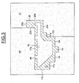
- the mold comprises a first portion 46, for example made of sand and defining the axial outer surface 17a of the body 17, a front radial surface 17b, a recess 17c, the bore 2a which forms the bore of the outer ring 2 and the rib 10.
- the mold also comprises a second portion 47 defining, by complementary shape, the outer surface 20a of the collar 20, an end surface 20b of the collar 20, which also forms a frontal radial surface of the body 17, and an inner surface 20c of the collar 20.
- the front surface 20d of the collar 20 opposite the front surface 20b is provided by the first portion 46 of the mold.
- the surface 20d joins the outer surface 17a of the body 17.
- the second portion 47 of the mold joins the first portion at the end of the bore 2a and is in contact with the radial surface 17d of the body 17, the radial surfaces 17d and inner 20c joining through a rib 17th.
- the body 17 further comprises a plurality of openings 48 formed from the outer surface 17a and providing communication between the cavity 18 and the outside.
- the cavity 18 and the openings 48 are filled with a sand-based molding core.
- the first and second parts 46 and 47 of the mold are broken.
- the openings 48 are unobstructed.
- the sand core occupying the cavity 18 is withdrawn through the openings 48 and then replaced by the damping material 19.
- the openings 48 are simply disengaged and then closed, for example with a screwed or brazed cap .
- the sand core then forms the damping material 19.
- the outer ring 2 can then be resumed during machining steps to finish the surfaces.
- the cavity 18 is in the form of an open groove on a face of the body 17, for example a radial face. A sealing flange of the cavity 18 is then provided.
- the rolling bearing can then be mounted in a movable part and a gantry of medical imaging apparatus.
- the ring can provide a multiple damping effect by providing the addition of an additional damping material, such as the material 19 disposed within the body 17.
- An additional effect can be obtained by the presence of damping rings arranged between the son forming the raceways and the body of the ring.
Landscapes
- Engineering & Computer Science (AREA)
- General Engineering & Computer Science (AREA)
- Mechanical Engineering (AREA)
- Rolling Contact Bearings (AREA)
Description
- La présente invention concerne le domaine des paliers à roulement utilisés en particulier dans des dispositifs d'imagerie médicale tels que des scanners.
- De tels roulements présentent généralement un diamètre important, de l'ordre d'un mètre, et tournent à une vitesse de quelques centaines de tours/minute, par exemple entre 200 et 300.
- Les exigences de précision et de robustesse imposent l'utilisation de roulements suffisamment rigides comportant un grand nombre d'éléments roulants. On pourra à cet égard se référer au document
US 4, 458, 959 qui décrit un palier à roulement de diamètre important comprenant une pluralité de bagues comportant chacune un profilé creux. Toutefois, du fait de leur grand diamètre, de tels roulements ont tendance à transmettre des vibrations au portique sur lequel ils sont montés lors de l'utilisation du dispositif. Par effet de résonance et d'amplification, le portique génère à son tour un bruit souvent mal perçu par le patient et le personnel médical. - Dans les dispositifs de l'art antérieur, on a essayé de réduire le bruit en disposant des couches de matériau souple amortisseur, par exemple en élastomère, entre les chemins de roulement et les bagues. On peut se référer au document
EP 127 879 US 2005/8274 - De tels systèmes contribuent à abaisser le niveau du bruit et des vibrations, mais on cherche encore à réduire ces niveaux sonores et vibratoires.
- L'invention vise à remédier à ces inconvénients.
- L'invention propose un palier à roulement à très haut effet d'amortissement des vibrations, en particulier des vibrations de roulement.
- Le dispositif de palier à roulement comprend une bague extérieure dont le corps principal comporte un ou plusieurs éléments, une bague intérieure dont le corps principal comporte un ou plusieurs éléments, les bagues extérieure et intérieure comprenant chacune au moins un chemin de roulement, intégré ou rapporté, pour des éléments roulants disposés entre lesdites bagues au contact des chemins de roulement. Au moins un des éléments formant le corps principal ci-dessus comprend un matériau métallique à coefficient d'amortissement vibratoire supérieur à 0,0001.
- Préférablement, le coefficient d'amortissement vibratoire est supérieur ou égal à 0,001. Plus préférablement encore, le coefficient d'amortissement vibratoire est supérieur ou égal à 0,01. On entend par coefficient d'amortissement vibratoire, le rapport entre l'énergie acoustique émise par un échantillon du matériau considéré et l'énergie vibratoire reçue par ledit échantillon. Le coefficient d'amortissement vibratoire est donc le quotient d'une énergie par une énergie et s'exprime sans unité.
- L'amortissement d'une paroi ou d'un matériau caractérise sa capacité à dissiper une plus ou moins grande quantité d'énergie vibratoire lorsqu'elle est mise en mouvement par une excitation acoustique ou mécanique.
- Une paroi peu ou pas amortie aura une grande aptitude à émettre un rayonnement acoustique en cas d'excitation. A l'inverse, une paroi très amortie cesse de vibrer dès qu'on supprime l'excitation.
- La capacité d'amortissement d'un matériau est caractérisée par son facteur de perte η. Elle peut dépendre également du module de Young (E) exprimé en daN/cm2.
- Les valeurs de ces caractéristiques propres à chaque matériau varient en fonction de la fréquence mais aussi de la température.
- η peut se définir par la formule suivante :

- Avec Wloss : l'énergie perdue, et W2 : l'énergie récupérée
- Dans un mode de réalisation, ledit matériau comprend de la fonte, préférablement de la fonte grise. La fonte peut comprendre du graphite lamellaire ou nodulaire. A titre d'exemple, on peut utiliser de la fonte GG40.
- Dans un mode de réalisation, le matériau comprend un alliage manganèse-cuivre, par exemple du Sonostron®. L'alliage manganèse-cuivre peut être du type Z9225, Z9240, Z8861 ou encore Z9000. Le pourcentage massique de manganèse peut être compris entre 50 et 54%. Le pourcentage massique de cuivre peut être compris entre 38 et 42%. Le pourcentage massique d'aluminium peut être compris entre 3 et 5%. Le pourcentage massique de fer peut être compris entre 2 et 4%. Le pourcentage massique de nickel peut être compris entre 0,5 et 2%. D'éventuels autres constituants étant présents en pourcentages massiques individuels inférieurs à 1%.
- Dans un mode de réalisation, le matériau comprend un alliage cuivre-aluminium-manganèse à effet mémoire, par exemple de type maxidamp®.
- Au moins un élément de bague comprend en outre un matériau additionnel d'amortissement disposé dans une ou plusieurs parties creuses ménagées dans ledit élément. Le matériau additionnel peut comprendre des particules ou des molécules dont la friction provoquée par les vibrations du matériau environnant transforme, au moins en partie, l'énergie vibratoire en chaleur. Le matériau additionnel peut comprendre du sable. Le sable peut comprendre au moins en partie le sable utilisé dans le noyau du moule de fonderie pour la formation de la partie creuse de l'élément de bague destinée à contenir le matériau additionnel, le sable de fonderie étant laissé volontairement après refroidissement du métal de l'élément de bague. La sable peut être au moins en partie du sable rapporté dans la partie creuse de l'élément de bague.
- Dans un mode de réalisation, le matériau additionnel comprend un polymère, par exemple une mousse polyuréthane.
- Dans un mode de réalisation, le matériau additionnel comprend une mousse métallique.
- Dans un mode de réalisation, le matériau additionnel comprend une pâte de silicone introduite par au moins un trou dans la partie creuse après retrait du sable de fonderie.
- Dans un mode de réalisation, le matériau additionnel comprend du ciment. Le ciment peut être chargé ou non d'un autre matériau, par exemple un matériau favorisant l'amortissement des ondes acoustiques, par exemple un additif sous forme fibreuse ou granulaire.
- Dans un mode de réalisation, le matériau additionnel comprend du plomb.
- Le dispositif peut comprendre un moteur assurant la rotation d'une bague par rapport à l'autre.
- Le dispositif peut comprendre un système de détection du déplacement angulaire de la bague tournante.
- Dans un mode de réalisation, le dispositif de palier à roulement comprend une bague extérieure pourvue d'un ou plusieurs éléments, une bague intérieure pourvue d'un ou plusieurs éléments, les bagues extérieure et intérieure comprenant chacune au moins un chemin de roulement, intégré ou rapporté, pour des éléments roulants disposés entre lesdites bagues au contact des chemins de roulement, au moins un élément de bague comprenant en outre un matériau additionnel d'amortissement disposé dans une ou plusieurs parties creuses ménagées dans ledit élément. Ledit élément peut être annulaire et/ou métallique. Ledit élément peut comprendre une demi bague de forme annulaire.
- Lorsque les chemins de roulement d'au moins l'une des bagues extérieure et intérieure sont rapportés, ils peuvent avantageusement être réalisés sous la forme de fils annulaires rapportés, réalisés par exemple en acier traité. Ces fils annulaires présentent avantageusement une section transversale sensiblement circulaire, à l'exception d'une concavité formant un chemin de roulement.
- Lorsque les chemins de roulement d'au moins l'une des bagues extérieure et intérieure sont intégrés, ils peuvent, par exemple, être usinés directement sur ladite bague du roulement de façon à former un chemin de roulement pour les éléments roulants, par exemple de forme toroïdale lorsque des billes sont utilisées comme éléments roulants.
- Un procédé de fabrication d'au moins un élément de bague pour palier à roulement, peut comprendre les étapes dans lesquelles on moule un élément de bague en réservant au moins une partie creuse dans ledit élément de bague, ladite partie creuse étant remplie d'un matériau de remplissage. On remplit le moule d'un alliage métallique destiné à former ledit élément de bague. On peut ensuite, soit obturer les trous mettant en communication l'alvéole avec l'extérieur en y laissant le matériau de remplissage, par exemple du sable de fonderie, soit procéder au retrait du matériau de remplissage de fonderie et à son remplacement par un matériau amortisseur.
- Un appareil d'imagerie médicale peut comprendre un palier à roulement tel que décrit ci-dessus, disposé entre une partie non tournante et une partie tournante. La partie tournante peut supporter des capteurs. L'appareil peut être du type scanner ou appareil à résonance magnétique nucléaire.
- Grâce à cela, les bruits de fonctionnement de l'appareil sont considérablement réduits. La masse de la partie tournante n'est pas sensiblement modifiée. La réduction du bruit de fonctionnement accroît le confort et réduit la fatigue du patient et du personnel médical.
- La présente invention sera mieux comprise à l'étude de la description détaillée de quelques modes de réalisation pris à titre d'exemples nullement limitatifs et illustrés par les dessins annexés, sur lesquels :
- la
figure 1 est une demi-vue en coupe axiale d'un palier à roulement selon un mode de réalisation de l'invention ; - la
figure 2 est une demi-vue en coupe axiale d'un palier à roulement selon un autre mode de réalisation ; et - la
figure 3 est une demi-vue en coupe axiale d'une bague en cours de moulage. - Comme on peut le voir sur la
figure 1 , le palier à roulement 1 comprend une bague extérieure 2, une bague intérieure 3 comprenant deux parties 4 et 5, et deux rangées d'éléments roulants 6 et 7, par exemple des billes disposées entre les bagues extérieure 2 et intérieure 3. Des cages 8 et 9 maintiennent respectivement l'espacement circonférentiel des éléments roulants 6 et 7. - La bague extérieure 2 comporte un alésage 2a séparé en deux parties sensiblement égales par une nervure 10 en saillie radialement vers l'intérieur. La bague extérieure 2 comprend également deux fils annulaires rapportés 11 et 12 formant des chemins de roulement toroïdaux 13 et 14, respectivement pour les éléments roulants 6 et 7. Les fils 11 et 12 présentent une section transversale sensiblement circulaire, à l'exception d'une concavité formant les chemins de roulement toroïdaux 13 et 14. Les fils 11 et 12 peuvent être réalisés en acier traité et roulés sur eux-mêmes pour former un anneau à bouts jointifs. La bague extérieure 2 est également munie de deux éléments d'amortissement 15 et 16, par exemple comprenant un élastomère. Les éléments d'amortissement 15 et 16 présentent une forme annulaire et sont disposés en contact avec l'alésage 2a et la nervure 10 d'un côté, et en contact avec le fil 11, 12 du côté opposé. Les éléments amortisseurs 15 et 16 sont disposés d'un côté et de l'autre de la nervure 10.
- Le corps principal 17 de la bague extérieure 2 comporte également une cavité intérieure 18 annulaire ou présentant plusieurs alvéoles en arc de cercle séparées les unes des autres. La cavité 18 laisse subsister des parois du corps 17 d'épaisseur suffisante. La cavité 18 est remplie d'un matériau amortisseur de vibrations 19. La nervure 10 peut être monobloc avec le corps 17. On entend par « corps » une partie principale de la bague supportant, directement ou indirectement, au moins un chemin de roulement. Le corps peut être une pièce de forme générale annulaire.
- Le matériau 19 peut comprendre du sable de fonderie, par exemple à base de silice, utilisé pour le moulage du corps 17 et laissé en place après moulage, le cas échéant après rebouchage des trous du corps 17 permettant de maintenir en place le sable de fonderie lors de la coulée du matériau formant le corps 17.
- Le sable de fonderie peut également être retiré et remplacé par un autre matériau amortisseur de vibrations, par exemple un autre sable, différent du sable utilisé initialement pour réaliser le moyeu du moule de fonderie. On peut également utiliser pour le matériau amortisseur 19 un polymère, par exemple une mousse polyuréthane ou une pâte silicone, ou bien un élastomère ou du caoutchouc. On peut également envisager comme matériau amortisseur du ciment, chargé ou non d'un autre matériau, par exemple un matériau de renforcement, sous forme de fibres ou de granules. Enfin, on peut envisager l'utilisation d'un métal, par exemple du plomb, pour le remplissage de la cavité 18. Une mousse métallique peut également être envisagée pour le remplissage des cavités 18. Dans le cas du ciment, on choisit de préférence un ciment présentant un coefficient d'amortissement vibratoire élevé, par exemple compris entre 0,01 et 0,6, de préférence supérieur à 0,1. Le sable peut également être choisi pour présenter un coefficient d'amortissement vibratoire élevé, par exemple compris entre 0,05 et 0,2, de préférence supérieur à 0,1. Le caoutchouc naturel peut présenter un coefficient d'amortissement vibratoire compris entre 0,03 et 0,5, par exemple de l'ordre de 0,04.
- Le corps 17, qui comprend la nervure 10, peut être réalisé en un alliage métallique moulé, comme illustré sur la
figure 3 . Le matériau du corps 17 présente un coefficient d'amortissement vibratoire supérieur à 0,0001. - Le matériau du corps 17 peut être de la fonte, par exemple une fonte grise. On peut choisir une fonte de type GG40. La fonte, avec graphite lamellaire ou nodulaire, peut présenter un coefficient d'amortissement vibratoire compris entre 0,01 et 0,02, plus de 100 fois supérieur à celui de l'acier couramment utilisé pour la fabrication des bagues de roulement et plus de 140 fois supérieur à celui de l'aluminium parfois utilisé pour la fabrication des bagues de roulement.
- Le matériau du corps 17 de la bague peut être un alliage manganèse-cuivre, dont une nuance est connue sous la dénomination Sonoston® fourni par Stone Manganese Marine Ltd. L'alliage manganèse-cuivre peut comprendre un pourcentage massique de manganèse compris entre 50 et 54%, un pourcentage massique de cuivre compris entre 38 et 41%, un pourcentage massique de fer compris entre 2 et 4%, de préférence entre 2,8 et 3,1 %, un pourcentage massique d'aluminium compris entre 3 et 5%, de préférence entre 3,9 et 4,4%, un pourcentage massique de nickel compris entre 0 et 2%, de préférence entre 0,8 et 1,4%, un pourcentage massique de zinc compris entre 0,1 et 1%, de préférence entre 0,15 et 0,6%, un pourcentage massique de silicium compris entre 0,01 et 0,3%, de préférence entre 0,08 et 0,16%, un pourcentage massique de carbone compris entre 0,01 et 0,1%, de préférence entre 0,015 et 0,05%, un pourcentage massique de plomb compris entre 0,01 et 0,05, de préférence entre 0,015 et 0,035%, et un pourcentage massique d'étain compris entre 0 et 0,05%, de préférence entre 0,01 et 0,03%. On peut utiliser les nuances Z9225, Z9240, Z8861, ou encore Z9000. L'alliage manganèse-cuivre peut être fondu et moulé, et présente d'excellente propriétés d'absorption du bruit et des vibrations.
- Le matériau du corps 17 de bague peut être un alliage cuivre-aluminium-manganèse. Ce type d'alliage peut présenter un effet mémoire et un excellent amortissement des vibrations. Un exemple d'alliage CuAIMn est connu sous la dénomination Maxidamp®, notamment étudié par l'Université Technique de Clausthal, Allemagne.
- Le corps 17 de la bague extérieure 2 comprend un collet 20, s'étendant radialement vers l'extérieur à partir d'une extrémité axiale du corps 17. Une pluralité de trous 21 peuvent être ménagés dans le collet 20 pour la fixation de la bague extérieure 2. La cavité 18 peut s'étendre axialement jusqu'au niveau du collet 20, ce qui accroît la capacité d'amortissement de la bague extérieure 2 et permet de conserver une épaisseur de paroi du corps 17 relativement constante, ce qui facilite l'opération de moulage.
- La demi-bague 4 présente un corps 22 réalisé en acier et un fil 23 muni d'un chemin de roulement 24 en contact avec les éléments roulants 6, axialement à l'opposé du chemin de roulement 13 du fil 11. Le fil 23 est disposé en appui contre une surface radiale et contre une surface axiale du corps 22 de la demi-bague 4. Le corps 22 supporte un joint d'étanchéité 25 à lèvres frottant contre une surface sensiblement radiale du corps 17 de la bague extérieure 2. Le joint d'étanchéité 25 peut être muni d'un talon encastré dans une rainure ménagée dans le corps 22 et ouverte vers l'extérieur.
- La demi-bague 5 comporte un corps 26, par exemple réalisé en acier, et un fil 27 sur lequel est ménagé un chemin de roulement 28 pour les éléments roulants 7. Le fil 27 est en appui contre une surface radiale et contre une surface axiale du corps 26. Chaque rangée d'éléments roulants 6 et 7 est en appui diagonal, entre d'une part un fil extérieur, respectivement 11, 12, disposé entre les plans radiaux passant par le centre des rangées d'éléments roulants 6 et 7 et un fil intérieur 23, 27 disposé à l'extérieur desdits plans radiaux. Le corps 26 de la demi-bague 5 supporte également un joint d'étanchéité 29 à lèvres frottant sur une surface radiale du corps 17 de la bague extérieure 2. Le joint d'étanchéité 29 comprend un talon disposé dans une rainure du corps 26, ouverte sur l'extérieur. L'étanchéité entre les demi-bagues intérieures 4 et 5 est assurée par un joint statique 30 disposé dans une rainure de la demi-bague 5 et en contact avec la demi-bague 4. L'étanchéité entre les demi-bagues 4 et 5 peut également être renforcée par une chicane formée par les formes respectives en contact des demi-bagues 4 et 5. Les fils 23 et 27 sont réalisés de la même manière que les fils 11 et 12 et peuvent également être en acier traité. Des éléments amortisseurs analogues aux éléments 15 et 16 paraissent également être prévus entre les fils 23, 27 et les demi-bagues correspondantes 4 et 5.
- Dans le mode de réalisation illustré sur la
figure 1 , les demi-bagues 4 et 5 sont munies de perçages 31, 32, pouvant être filetés, et destinés à la fixation sur ou avec d'autres éléments. La demi-bague 4 supporte un anneau codeur 33, par exemple de type magnétique ou encore optique, fixé par des vis 34 au corps 22. La bague extérieure 2 supporte un bloc capteur 35, comprenant une ou plusieurs cellules de détection, ledit bloc étant fixé par des vis 36 au corps 17. Le codeur 33 et le bloc capteur 35 sont disposés l'un en face de l'autre avec un entrefer radial à l'extérieur de la zone des éléments roulants délimitée et protégée par les joints d'étanchéité 25 et 29. Le cas échéant, un capot de protection peut être prévu pour protéger le codeur 33 et le bloc capteur 35. Le roulement comporte ainsi des moyens aptes à détecter le déplacement angulaire de la bague tournante. - Du côté axialement opposé, le roulement est équipé d'un moteur couple à aimants permanents, par exemple samarium-cobalt. Le moteur couple comporte un élément 37 formant stator et fixé au corps 17 de la bague extérieure par des vis 38 et un élément intérieur 40 formant rotor et fixé à la demi-bague 5 par des vis 41. Le stator 37 comporte des noyaux en fer et des bobinages et le rotor comporte un anneau aimanté. Le moteur couple entraîne en rotation la bague intérieure 3 par rapport à la bague extérieure 2. Les éléments roulants 6 et 7 se déplacent entre les chemins de roulement, respectivement 13 et 24, 14 et 28 en étant en contact oblique avec lesdits chemins. Les fils formant les chemins de roulement sont réalisés en acier traité, afin d'offrir la dureté nécessaire à un bon fonctionnement. Les demi-bagues intérieures 4 et 5 peuvent être réalisées en acier non traité, ce qui s'avère économique.
- La bague extérieure 2 assure un double amortissement des vibrations de par le matériau formant le corps 17 présentant un fort coefficient d'amortissement vibratoire et de par la présence du matériau amortisseur 19 dans le corps 17, d'où une très faible transmission des vibrations aux éléments de fixation qui peuvent être disposés dans les trous 21 du collet 20. Un amortissement supplémentaire est assuré par les anneaux souples 15 et 16 disposés entre les fils 11 et 12 d'une part et le corps 17 de la bague extérieure 2.
- Sur la
figure 2 , les références des éléments semblables ont été conservées. Ce mode de réalisation se distingue du précédent par plusieurs caractéristiques, qui peuvent être prises seules ou en combinaison. La bague extérieure 2 est réalisée en deux demi-bagues 42 et 43, fixées l'une à l'autre par des vis 44. Chaque corps de demi-bague 42, 43 comprend une cavité 18 munie d'un matériau amortisseur 19. - Les fils extérieurs 11 et 12 et les anneaux souples 15 et 16 sont disposés axialement à l'opposé l'un de l'autre, en d'autres termes en-dehors de l'espace défini par les plans radiaux passant par le centre des éléments roulants 6 et 7. Inversement, les fils intérieurs 23 et 27 sont disposés à l'intérieur desdits plans radiaux.
- La bague intérieure 3 est réalisée de façon monobloc, par exemple en acier, et comprend sur sa surface extérieure une nervure 45 disposée axialement sensiblement au milieu entre les éléments roulants 6 et 7. La nervure 45 sert d'appui aux fils intérieurs 23 et 27.
- Selon l'application choisie, on peut prévoir une bague intérieure monobloc et deux demi-bagues extérieures ou l'inverse, comme sur la
figure 1 . - Sur la
figure 3 , est montré plus en détail un moule pour le moulage du corps 17 de la bague extérieure 2, illustré sur lafigure 1 . Le moule comprend une première partie 46, par exemple réalisée à base de sable et définissant la surface extérieure axiale 17a du corps 17, une surface radiale frontale 17b, un renfoncement 17c, l'alésage 2a qui forme l'alésage de la bague extérieure 2 et la nervure 10. Le moule comprend également une deuxième partie 47 définissant, par complémentarité de forme, la surface extérieure 20a du collet 20, une surface d'extrémité 20b du collet 20, qui forme également une surface radiale frontale du corps 17, et une surface intérieure 20c du collet 20. La surface frontale 20d du collet 20 opposée à la surface frontale 20b est assurée par la première partie 46 du moule. La surface 20d rejoint la surface extérieure 17a du corps 17. La deuxième partie 47 du moule rejoint la première partie à l'extrémité de l'alésage 2a et est en contact avec la surface radiale 17d du corps 17, les surfaces radiales 17d et intérieures 20c se rejoignant par l'intermédiaire d'une nervure 17e. Le corps 17 comprend en outre une pluralité d'ouvertures 48 ménagées à partir de la surface extérieure 17a et assurant une communication entre la cavité 18 et l'extérieur. - Au stade de fabrication illustré sur la
figure 3 , immédiatement après coulée de l'alliage métallique dans le moule, la cavité 18 et les ouvertures 48 sont remplies d'un noyau de moulage à base de sable. Après refroidissement, les première et deuxième parties 46 et 47 du moule sont brisées. Les ouvertures 48 sont dégagées. Dans une première variante, le noyau en sable occupant la cavité 18 est retiré par les ouvertures 48, puis remplacé par le matériau amortisseur 19. Dans une autre variante, les ouvertures 48 sont simplement dégagées puis obturées, par exemple avec un bouchon vissé ou brasé. Le noyau en sable forme alors le matériau amortisseur 19. La bague extérieure 2 peut ensuite être reprise au cours d'étapes d'usinage pour assurer la finition des surfaces. - Dans un mode de réalisation non représenté, la cavité 18 se présente sous la forme d'une rainure ouverte sur une face du corps 17, par exemple une face radiale. Un flasque d'obturation de la cavité 18 est alors prévu.
- Bien entendu, ou pourrait également prévoir des cavités remplies d'un matériau amortisseur de vibrations dans la ou les bagues intérieures 3, 4, 5.
- Le palier à roulement peut ensuite être monté en une partie mobile et un portique d'appareil d'imagerie médicale.
- Grâce à l'invention, on forme une bague de roulement à effet amortisseur très élevé grâce au matériau formant le corps de ladite bague de roulement, ledit matériau possédant un coefficient d'amortissement vibratoire élevé. En outre, la bague peut assurer un effet d'amortissement multiple en prévoyant l'adjonction d'un matériau amortisseur supplémentaire, tel que le matériau 19 disposé à l'intérieur du corps 17. Un effet supplémentaire peut encore être obtenu par la présence des anneaux amortisseurs disposés entre les fils formant les chemins de roulement et le corps de la bague.
Claims (19)
- Dispositif de palier à roulement (1) comprenant une bague extérieure (2) dont le corps principal (17) comporte un ou plusieurs éléments, une bague intérieure (3) dont le corps principal comporte un ou plusieurs éléments, les bagues extérieure et intérieure comprenant chacune au moins un chemin de roulement, intégré ou rapporté, pour des éléments roulants (6) disposés entre lesdites bagues au contact des chemins de roulement, le corps principal d'au moins l'une des bagues intérieure et extérieure comportant une cavité intérieure annulaire ou présentant plusieurs alvéoles séparées les unes des autres, caractérisé en ce que le dit corps principal comprend un matériau métallique à coefficient d'amortissement vibratoire supérieur à 0,0001 et en ce que la cavité est remplie d'un matériau additionnel (19) d'amortissement.
- Dispositif selon la revendication 1, dans lequel ledit matériau métallique comprend de la fonte grise lamellaire ou nodulaire.
- Dispositif selon la revendication 1 ou 2, dans lequel ledit matériau métallique comprend un alliage à base de manganèse et de cuivre.
- Dispositif selon l'une quelconque des revendications précédentes, dans lequel ledit matériau métallique comprend un alliage à base de cuivre, d'aluminium et manganèse, présentant un effet mémoire.
- Dispositif selon la revendication 1, dans lequel le matériau additionnel comprend des particules ou des molécules dont la friction provoquée par les vibrations du matériau environnant transforme, au moins en partie, l'énergie vibratoire en chaleur.
- Dispositif selon la revendication 5, lequel le matériau additionnel comprend du sable.
- Dispositif selon la revendication 6, dans lequel le sable comprend au moins en partie un sable utilisé dans le noyau du moule de fonderie pour la formation de la ou des parties creuses destinées à contenir le matériau amortisseur additionnel et laissé volontairement après refroidissement du métal de l'élément de bague.
- Dispositif selon la revendication 6, dans lequel le sable est rapporté dans la ou les parties creuses (18) après refroidissement du métal des bagues.
- Dispositif selon l'une quelconque des revendications 1 à 8, dans lequel le matériau additionnel comprend un polymère.
- Dispositif selon la revendication 9, dans lequel le matériau polymère comprend une mousse polyuréthane.
- Dispositif selon la revendication 9 ou 10, dans lequel le matériau additionnel comprend une pâte silicone.
- Dispositif selon les revendications 1 à 11, dans lequel le matériau additionnel comprend une mousse métallique.
- Dispositif selon l'une quelconque des revendications 1 à 12, dans lequel le matériau additionnel comprend un ciment chargé ou non d'un ou plusieurs additifs sous forme fibreuse ou granulaire.
- Dispositif selon l'une quelconque des revendications 1 à 13, dans lequel le matériau additionnel comprend du plomb.
- Dispositif selon les revendications 1 à 14, comprenant un moteur pour la rotation d'une bague par rapport à l'autre.
- Dispositif selon les revendications 1 à 15, comprenant un système de détection de déplacement angulaire de la bague tournante.
- Dispositif selon l'une des revendications précédentes dans lequel les chemins de roulement des bagues extérieure et intérieure comprennent des fils annulaires (11, 12; 23,27) formant des chemins de roulement pour les éléments roulants.
- Dispositif selon la revendication 17 dans lequel les fils annulaires sont réalisés en acier traité.
- Appareil d'imagerie médicale comprenant un palier à roulement suivant l'une quelconque des revendications précédentes, le palier étant disposé entre une partie non tournante et une partie tournante.
Applications Claiming Priority (1)
| Application Number | Priority Date | Filing Date | Title |
|---|---|---|---|
| FR0752868A FR2911650B1 (fr) | 2007-01-24 | 2007-01-24 | Dispositif de palier a roulement. |
Publications (3)
| Publication Number | Publication Date |
|---|---|
| EP1956257A2 EP1956257A2 (fr) | 2008-08-13 |
| EP1956257A3 EP1956257A3 (fr) | 2009-06-17 |
| EP1956257B1 true EP1956257B1 (fr) | 2013-03-20 |
Family
ID=38516134
Family Applications (1)
| Application Number | Title | Priority Date | Filing Date |
|---|---|---|---|
| EP08290048A Not-in-force EP1956257B1 (fr) | 2007-01-24 | 2008-01-21 | Dispositif de palier à roulement |
Country Status (2)
| Country | Link |
|---|---|
| EP (1) | EP1956257B1 (fr) |
| FR (1) | FR2911650B1 (fr) |
Families Citing this family (5)
| Publication number | Priority date | Publication date | Assignee | Title |
|---|---|---|---|---|
| BR112014014728A2 (pt) * | 2011-12-20 | 2017-06-13 | Koninklijke Philips Nv | sistema de imagem; e método |
| DE102013206101A1 (de) * | 2013-04-08 | 2014-10-30 | Schaeffler Technologies Gmbh & Co. Kg | Lagerring und Dämpfungshülse |
| FR3069294B1 (fr) * | 2017-07-19 | 2019-08-23 | Ntn-Snr Roulements | Procede de fabrication d’une bague metallique monobloc allegee de palier lisse ou a roulement, et palier comportant au moins une bague obtenue par le procede |
| CN113007214B (zh) * | 2021-03-09 | 2022-04-01 | 上海人本精密机械有限公司 | 组合式高速精密轴承 |
| EP4177490A1 (fr) * | 2021-11-05 | 2023-05-10 | Siemens Aktiengesellschaft | Élément palier pour un arbre en rotation, composant moulé en métal léger et machine électrique |
Family Cites Families (11)
| Publication number | Priority date | Publication date | Assignee | Title |
|---|---|---|---|---|
| DE1174999B (de) * | 1961-05-29 | 1964-07-30 | Friedrichshuette Ag | Grauguss zur Herstellung von Gegenstaenden, die bei hoher mechanischer Beanspruchung eine gute Formbestaendigkeit aufweisen |
| DE1226429B (de) * | 1962-01-31 | 1966-10-06 | Daimler Benz Ag | Leichtmetallgehaeuse fuer Zahnraedergetriebe von Kraftfahrzeugen, insbesondere Zahnraeder-wechselgetriebe |
| FR1480448A (fr) * | 1965-05-04 | 1967-05-12 | Int Nickel Ltd | Perfectionnements aux fontes à graphite |
| GB1106018A (en) * | 1965-08-27 | 1968-03-13 | Ass Elect Ind | Alloys for vibration damping |
| DE3022227C2 (de) | 1980-06-13 | 1983-07-07 | Hoesch Werke Ag, 4600 Dortmund | Großwälzlager in Leichtbauweise |
| DE3320457A1 (de) | 1983-06-07 | 1984-12-20 | Hoesch Ag, 4600 Dortmund | Drahtwaelzlager |
| DE4228847C1 (de) * | 1992-08-29 | 1993-11-25 | Daimler Benz Ag | Metallischer Dämpfungskörper |
| DE19605551C2 (de) * | 1996-02-15 | 2000-05-31 | Freudenberg Carl Fa | Aktiver Schwingungstilger |
| US5976709A (en) * | 1996-05-31 | 1999-11-02 | Hitachi Kinzoku Kabushiki Kaisha | Aluminum alloy member, with insert provided therein, possessing improved damping capacity and process for producing the same |
| DE10331150B4 (de) | 2003-07-09 | 2007-07-19 | Franke & Heydrich Kg | Wälzlager in Form einer Dreh- und/oder Linearführung |
| JP4750469B2 (ja) * | 2005-05-25 | 2011-08-17 | キヤノン株式会社 | ベアリング |
-
2007
- 2007-01-24 FR FR0752868A patent/FR2911650B1/fr not_active Expired - Fee Related
-
2008
- 2008-01-21 EP EP08290048A patent/EP1956257B1/fr not_active Not-in-force
Also Published As
| Publication number | Publication date |
|---|---|
| FR2911650B1 (fr) | 2009-10-16 |
| EP1956257A2 (fr) | 2008-08-13 |
| EP1956257A3 (fr) | 2009-06-17 |
| FR2911650A1 (fr) | 2008-07-25 |
Similar Documents
| Publication | Publication Date | Title |
|---|---|---|
| EP1956257B1 (fr) | Dispositif de palier à roulement | |
| EP1764524B1 (fr) | Poulie de transmission de puissance | |
| FR2768271A1 (fr) | Procede de fabrication d'un rotor pour machine electrique rotative, rotor et machine concernes | |
| EP2935939B1 (fr) | Dispositif d'absorption de vibrations | |
| FR2966208A1 (fr) | Boitier de liaison entre un arbre d'entrainement de soufflante de moteur et un palier de roulement | |
| CN114576343A (zh) | 用于行星齿轮传动机构的分离环 | |
| EP2935938B1 (fr) | Dispositif d'absorption de vibrations | |
| JP2016014423A (ja) | インホイールモータ駆動装置 | |
| FR3094051A1 (fr) | Bague à cage de type écureuil en bi-matière composite et métal, et ensemble de roulement à éléments roulants équipé d’une telle bague | |
| FR3064764B1 (fr) | Generateur d'efforts dynamiques comprenant au moins deux balourds et actionneur comprenant de tels generateurs | |
| FR3036150B1 (fr) | Dispositif d'amortissement d'oscillations de torsion | |
| EP2888490A1 (fr) | Cage pour palier à roulement, palier à roulement et direction électrique de véhicule automobile | |
| FR2804476A1 (fr) | Systeme amortisseur et centreur de roulement pour pompe a vide sur palier magnetique | |
| FR2835580A1 (fr) | Palier a roulement, notamment pour moteur electrique | |
| CN1770600A (zh) | 无刷电动机及其制造方法 | |
| JP2006226400A (ja) | シャフト装置 | |
| CN102203465B (zh) | 一种用于重型船用变速器的轴承装置 | |
| EP3418595B1 (fr) | Roulement à billes de pièce d'horlogerie | |
| FR2921140A1 (fr) | Dispositif de palier a roulement, en particulier pour appareil medical | |
| FR3053287A1 (fr) | Ensemble de montage d'un dispositif de pulsion d'air | |
| FR3057927B1 (fr) | Amortisseur de torsion et vehicule automobile | |
| FR3116571A1 (fr) | Un contrepoids pour un compresseur à spirales | |
| FR3112825A1 (fr) | ensemble rotatif, notamment pour un guidage de roue de véhicule automobile | |
| FR3105319A1 (fr) | Bague pour élément de liaison, élément de liaison et procédé de fabrication correspondant | |
| CA2722217A1 (fr) | Assemblage de rouleau porteur allege pour convoyeur et utilisations correspondantes |
Legal Events
| Date | Code | Title | Description |
|---|---|---|---|
| PUAI | Public reference made under article 153(3) epc to a published international application that has entered the european phase |
Free format text: ORIGINAL CODE: 0009012 |
|
| AK | Designated contracting states |
Kind code of ref document: A2 Designated state(s): AT BE BG CH CY CZ DE DK EE ES FI FR GB GR HR HU IE IS IT LI LT LU LV MC MT NL NO PL PT RO SE SI SK TR |
|
| AX | Request for extension of the european patent |
Extension state: AL BA MK RS |
|
| PUAL | Search report despatched |
Free format text: ORIGINAL CODE: 0009013 |
|
| AK | Designated contracting states |
Kind code of ref document: A3 Designated state(s): AT BE BG CH CY CZ DE DK EE ES FI FR GB GR HR HU IE IS IT LI LT LU LV MC MT NL NO PL PT RO SE SI SK TR |
|
| AX | Request for extension of the european patent |
Extension state: AL BA MK RS |
|
| RIC1 | Information provided on ipc code assigned before grant |
Ipc: F16C 33/62 20060101ALI20090514BHEP Ipc: F16C 35/00 20060101AFI20090514BHEP Ipc: F16C 35/04 20060101ALI20090514BHEP Ipc: F16F 1/02 20060101ALI20090514BHEP |
|
| 17P | Request for examination filed |
Effective date: 20090925 |
|
| 17Q | First examination report despatched |
Effective date: 20091102 |
|
| AKX | Designation fees paid |
Designated state(s): AT BE BG CH CY CZ DE DK EE ES FI FR GB GR HR HU IE IS IT LI LT LU LV MC MT NL NO PL PT RO SE SI SK TR |
|
| GRAP | Despatch of communication of intention to grant a patent |
Free format text: ORIGINAL CODE: EPIDOSNIGR1 |
|
| GRAS | Grant fee paid |
Free format text: ORIGINAL CODE: EPIDOSNIGR3 |
|
| GRAA | (expected) grant |
Free format text: ORIGINAL CODE: 0009210 |
|
| AK | Designated contracting states |
Kind code of ref document: B1 Designated state(s): AT BE BG CH CY CZ DE DK EE ES FI FR GB GR HR HU IE IS IT LI LT LU LV MC MT NL NO PL PT RO SE SI SK TR |
|
| REG | Reference to a national code |
Ref country code: GB Ref legal event code: FG4D Free format text: NOT ENGLISH |
|
| REG | Reference to a national code |
Ref country code: CH Ref legal event code: EP |
|
| REG | Reference to a national code |
Ref country code: IE Ref legal event code: FG4D Free format text: LANGUAGE OF EP DOCUMENT: FRENCH |
|
| REG | Reference to a national code |
Ref country code: AT Ref legal event code: REF Ref document number: 602255 Country of ref document: AT Kind code of ref document: T Effective date: 20130415 |
|
| REG | Reference to a national code |
Ref country code: DE Ref legal event code: R096 Ref document number: 602008023009 Country of ref document: DE Effective date: 20130516 |
|
| PG25 | Lapsed in a contracting state [announced via postgrant information from national office to epo] |
Ref country code: LT Free format text: LAPSE BECAUSE OF FAILURE TO SUBMIT A TRANSLATION OF THE DESCRIPTION OR TO PAY THE FEE WITHIN THE PRESCRIBED TIME-LIMIT Effective date: 20130320 Ref country code: ES Free format text: LAPSE BECAUSE OF FAILURE TO SUBMIT A TRANSLATION OF THE DESCRIPTION OR TO PAY THE FEE WITHIN THE PRESCRIBED TIME-LIMIT Effective date: 20130701 Ref country code: SE Free format text: LAPSE BECAUSE OF FAILURE TO SUBMIT A TRANSLATION OF THE DESCRIPTION OR TO PAY THE FEE WITHIN THE PRESCRIBED TIME-LIMIT Effective date: 20130320 Ref country code: NO Free format text: LAPSE BECAUSE OF FAILURE TO SUBMIT A TRANSLATION OF THE DESCRIPTION OR TO PAY THE FEE WITHIN THE PRESCRIBED TIME-LIMIT Effective date: 20130620 Ref country code: BG Free format text: LAPSE BECAUSE OF FAILURE TO SUBMIT A TRANSLATION OF THE DESCRIPTION OR TO PAY THE FEE WITHIN THE PRESCRIBED TIME-LIMIT Effective date: 20130620 |
|
| REG | Reference to a national code |
Ref country code: AT Ref legal event code: MK05 Ref document number: 602255 Country of ref document: AT Kind code of ref document: T Effective date: 20130320 |
|
| REG | Reference to a national code |
Ref country code: LT Ref legal event code: MG4D |
|
| PG25 | Lapsed in a contracting state [announced via postgrant information from national office to epo] |
Ref country code: GR Free format text: LAPSE BECAUSE OF FAILURE TO SUBMIT A TRANSLATION OF THE DESCRIPTION OR TO PAY THE FEE WITHIN THE PRESCRIBED TIME-LIMIT Effective date: 20130621 Ref country code: FI Free format text: LAPSE BECAUSE OF FAILURE TO SUBMIT A TRANSLATION OF THE DESCRIPTION OR TO PAY THE FEE WITHIN THE PRESCRIBED TIME-LIMIT Effective date: 20130320 Ref country code: LV Free format text: LAPSE BECAUSE OF FAILURE TO SUBMIT A TRANSLATION OF THE DESCRIPTION OR TO PAY THE FEE WITHIN THE PRESCRIBED TIME-LIMIT Effective date: 20130320 Ref country code: SI Free format text: LAPSE BECAUSE OF FAILURE TO SUBMIT A TRANSLATION OF THE DESCRIPTION OR TO PAY THE FEE WITHIN THE PRESCRIBED TIME-LIMIT Effective date: 20130320 |
|
| REG | Reference to a national code |
Ref country code: NL Ref legal event code: VDEP Effective date: 20130320 |
|
| PG25 | Lapsed in a contracting state [announced via postgrant information from national office to epo] |
Ref country code: HR Free format text: LAPSE BECAUSE OF FAILURE TO SUBMIT A TRANSLATION OF THE DESCRIPTION OR TO PAY THE FEE WITHIN THE PRESCRIBED TIME-LIMIT Effective date: 20130320 |
|
| PG25 | Lapsed in a contracting state [announced via postgrant information from national office to epo] |
Ref country code: AT Free format text: LAPSE BECAUSE OF FAILURE TO SUBMIT A TRANSLATION OF THE DESCRIPTION OR TO PAY THE FEE WITHIN THE PRESCRIBED TIME-LIMIT Effective date: 20130320 Ref country code: SK Free format text: LAPSE BECAUSE OF FAILURE TO SUBMIT A TRANSLATION OF THE DESCRIPTION OR TO PAY THE FEE WITHIN THE PRESCRIBED TIME-LIMIT Effective date: 20130320 Ref country code: PT Free format text: LAPSE BECAUSE OF FAILURE TO SUBMIT A TRANSLATION OF THE DESCRIPTION OR TO PAY THE FEE WITHIN THE PRESCRIBED TIME-LIMIT Effective date: 20130722 Ref country code: NL Free format text: LAPSE BECAUSE OF FAILURE TO SUBMIT A TRANSLATION OF THE DESCRIPTION OR TO PAY THE FEE WITHIN THE PRESCRIBED TIME-LIMIT Effective date: 20130320 Ref country code: IS Free format text: LAPSE BECAUSE OF FAILURE TO SUBMIT A TRANSLATION OF THE DESCRIPTION OR TO PAY THE FEE WITHIN THE PRESCRIBED TIME-LIMIT Effective date: 20130720 Ref country code: RO Free format text: LAPSE BECAUSE OF FAILURE TO SUBMIT A TRANSLATION OF THE DESCRIPTION OR TO PAY THE FEE WITHIN THE PRESCRIBED TIME-LIMIT Effective date: 20130320 Ref country code: EE Free format text: LAPSE BECAUSE OF FAILURE TO SUBMIT A TRANSLATION OF THE DESCRIPTION OR TO PAY THE FEE WITHIN THE PRESCRIBED TIME-LIMIT Effective date: 20130320 Ref country code: CZ Free format text: LAPSE BECAUSE OF FAILURE TO SUBMIT A TRANSLATION OF THE DESCRIPTION OR TO PAY THE FEE WITHIN THE PRESCRIBED TIME-LIMIT Effective date: 20130320 |
|
| PG25 | Lapsed in a contracting state [announced via postgrant information from national office to epo] |
Ref country code: CY Free format text: LAPSE BECAUSE OF FAILURE TO SUBMIT A TRANSLATION OF THE DESCRIPTION OR TO PAY THE FEE WITHIN THE PRESCRIBED TIME-LIMIT Effective date: 20130320 Ref country code: PL Free format text: LAPSE BECAUSE OF FAILURE TO SUBMIT A TRANSLATION OF THE DESCRIPTION OR TO PAY THE FEE WITHIN THE PRESCRIBED TIME-LIMIT Effective date: 20130320 |
|
| PLBE | No opposition filed within time limit |
Free format text: ORIGINAL CODE: 0009261 |
|
| STAA | Information on the status of an ep patent application or granted ep patent |
Free format text: STATUS: NO OPPOSITION FILED WITHIN TIME LIMIT |
|
| PG25 | Lapsed in a contracting state [announced via postgrant information from national office to epo] |
Ref country code: DK Free format text: LAPSE BECAUSE OF FAILURE TO SUBMIT A TRANSLATION OF THE DESCRIPTION OR TO PAY THE FEE WITHIN THE PRESCRIBED TIME-LIMIT Effective date: 20130320 |
|
| 26N | No opposition filed |
Effective date: 20140102 |
|
| PG25 | Lapsed in a contracting state [announced via postgrant information from national office to epo] |
Ref country code: IT Free format text: LAPSE BECAUSE OF FAILURE TO SUBMIT A TRANSLATION OF THE DESCRIPTION OR TO PAY THE FEE WITHIN THE PRESCRIBED TIME-LIMIT Effective date: 20130320 |
|
| REG | Reference to a national code |
Ref country code: DE Ref legal event code: R097 Ref document number: 602008023009 Country of ref document: DE Effective date: 20140102 |
|
| BERE | Be: lapsed |
Owner name: A.B. SKF Effective date: 20140131 |
|
| PG25 | Lapsed in a contracting state [announced via postgrant information from national office to epo] |
Ref country code: MC Free format text: LAPSE BECAUSE OF FAILURE TO SUBMIT A TRANSLATION OF THE DESCRIPTION OR TO PAY THE FEE WITHIN THE PRESCRIBED TIME-LIMIT Effective date: 20130320 Ref country code: LU Free format text: LAPSE BECAUSE OF FAILURE TO SUBMIT A TRANSLATION OF THE DESCRIPTION OR TO PAY THE FEE WITHIN THE PRESCRIBED TIME-LIMIT Effective date: 20140121 |
|
| REG | Reference to a national code |
Ref country code: CH Ref legal event code: PL |
|
| GBPC | Gb: european patent ceased through non-payment of renewal fee |
Effective date: 20140121 |
|
| PG25 | Lapsed in a contracting state [announced via postgrant information from national office to epo] |
Ref country code: CH Free format text: LAPSE BECAUSE OF NON-PAYMENT OF DUE FEES Effective date: 20140131 Ref country code: LI Free format text: LAPSE BECAUSE OF NON-PAYMENT OF DUE FEES Effective date: 20140131 |
|
| REG | Reference to a national code |
Ref country code: FR Ref legal event code: ST Effective date: 20140930 |
|
| REG | Reference to a national code |
Ref country code: IE Ref legal event code: MM4A |
|
| PG25 | Lapsed in a contracting state [announced via postgrant information from national office to epo] |
Ref country code: FR Free format text: LAPSE BECAUSE OF NON-PAYMENT OF DUE FEES Effective date: 20140131 Ref country code: GB Free format text: LAPSE BECAUSE OF NON-PAYMENT OF DUE FEES Effective date: 20140121 |
|
| PG25 | Lapsed in a contracting state [announced via postgrant information from national office to epo] |
Ref country code: BE Free format text: LAPSE BECAUSE OF NON-PAYMENT OF DUE FEES Effective date: 20140131 Ref country code: IE Free format text: LAPSE BECAUSE OF NON-PAYMENT OF DUE FEES Effective date: 20140121 |
|
| PG25 | Lapsed in a contracting state [announced via postgrant information from national office to epo] |
Ref country code: MT Free format text: LAPSE BECAUSE OF FAILURE TO SUBMIT A TRANSLATION OF THE DESCRIPTION OR TO PAY THE FEE WITHIN THE PRESCRIBED TIME-LIMIT Effective date: 20130320 |
|
| PGFP | Annual fee paid to national office [announced via postgrant information from national office to epo] |
Ref country code: DE Payment date: 20160331 Year of fee payment: 9 |
|
| PG25 | Lapsed in a contracting state [announced via postgrant information from national office to epo] |
Ref country code: HU Free format text: LAPSE BECAUSE OF FAILURE TO SUBMIT A TRANSLATION OF THE DESCRIPTION OR TO PAY THE FEE WITHIN THE PRESCRIBED TIME-LIMIT; INVALID AB INITIO Effective date: 20080121 Ref country code: TR Free format text: LAPSE BECAUSE OF FAILURE TO SUBMIT A TRANSLATION OF THE DESCRIPTION OR TO PAY THE FEE WITHIN THE PRESCRIBED TIME-LIMIT Effective date: 20130320 |
|
| REG | Reference to a national code |
Ref country code: DE Ref legal event code: R119 Ref document number: 602008023009 Country of ref document: DE |
|
| PG25 | Lapsed in a contracting state [announced via postgrant information from national office to epo] |
Ref country code: DE Free format text: LAPSE BECAUSE OF NON-PAYMENT OF DUE FEES Effective date: 20170801 |