EP1956265A2 - Procédé destiné à réduire les oscillations d'un composant essentiellement en forme de disque annulaire et composant en forme de disque annulaire - Google Patents
Procédé destiné à réduire les oscillations d'un composant essentiellement en forme de disque annulaire et composant en forme de disque annulaire Download PDFInfo
- Publication number
- EP1956265A2 EP1956265A2 EP08001020A EP08001020A EP1956265A2 EP 1956265 A2 EP1956265 A2 EP 1956265A2 EP 08001020 A EP08001020 A EP 08001020A EP 08001020 A EP08001020 A EP 08001020A EP 1956265 A2 EP1956265 A2 EP 1956265A2
- Authority
- EP
- European Patent Office
- Prior art keywords
- component
- shaped
- max
- recesses
- annular
- Prior art date
- Legal status (The legal status is an assumption and is not a legal conclusion. Google has not performed a legal analysis and makes no representation as to the accuracy of the status listed.)
- Granted
Links
Images





Classifications
-
- F—MECHANICAL ENGINEERING; LIGHTING; HEATING; WEAPONS; BLASTING
- F16—ENGINEERING ELEMENTS AND UNITS; GENERAL MEASURES FOR PRODUCING AND MAINTAINING EFFECTIVE FUNCTIONING OF MACHINES OR INSTALLATIONS; THERMAL INSULATION IN GENERAL
- F16F—SPRINGS; SHOCK-ABSORBERS; MEANS FOR DAMPING VIBRATION
- F16F15/00—Suppression of vibrations in systems; Means or arrangements for avoiding or reducing out-of-balance forces, e.g. due to motion
- F16F15/10—Suppression of vibrations in rotating systems by making use of members moving with the system
- F16F15/12—Suppression of vibrations in rotating systems by making use of members moving with the system using elastic members or friction-damping members, e.g. between a rotating shaft and a gyratory mass mounted thereon
- F16F15/131—Suppression of vibrations in rotating systems by making use of members moving with the system using elastic members or friction-damping members, e.g. between a rotating shaft and a gyratory mass mounted thereon the rotating system comprising two or more gyratory masses
- F16F15/13142—Suppression of vibrations in rotating systems by making use of members moving with the system using elastic members or friction-damping members, e.g. between a rotating shaft and a gyratory mass mounted thereon the rotating system comprising two or more gyratory masses characterised by the method of assembly, production or treatment
- F16F15/1315—Multi-part primary or secondary masses, e.g. assembled from pieces of sheet steel
-
- F—MECHANICAL ENGINEERING; LIGHTING; HEATING; WEAPONS; BLASTING
- F16—ENGINEERING ELEMENTS AND UNITS; GENERAL MEASURES FOR PRODUCING AND MAINTAINING EFFECTIVE FUNCTIONING OF MACHINES OR INSTALLATIONS; THERMAL INSULATION IN GENERAL
- F16F—SPRINGS; SHOCK-ABSORBERS; MEANS FOR DAMPING VIBRATION
- F16F15/00—Suppression of vibrations in systems; Means or arrangements for avoiding or reducing out-of-balance forces, e.g. due to motion
- F16F15/10—Suppression of vibrations in rotating systems by making use of members moving with the system
- F16F15/12—Suppression of vibrations in rotating systems by making use of members moving with the system using elastic members or friction-damping members, e.g. between a rotating shaft and a gyratory mass mounted thereon
- F16F15/131—Suppression of vibrations in rotating systems by making use of members moving with the system using elastic members or friction-damping members, e.g. between a rotating shaft and a gyratory mass mounted thereon the rotating system comprising two or more gyratory masses
- F16F15/139—Suppression of vibrations in rotating systems by making use of members moving with the system using elastic members or friction-damping members, e.g. between a rotating shaft and a gyratory mass mounted thereon the rotating system comprising two or more gyratory masses characterised by friction-damping means
Definitions
- the invention relates to a method for reducing vibrations of an overall annular disk-shaped component with at least one directed perpendicular to an axis of the component annular disk-shaped friction surface.
- the invention further relates to an annular disk-shaped component with such a friction surface.
- Vibrations especially in the audible frequency range as perceived as unpleasant vibrations, are a widespread problem when a sliding friction contact between two components.
- a typical example of such audible vibrations are squeaking noises that occur on brakes, clutches, etc.
- the invention is based on the object remedial measures for the occurrence of lying in particular in the auditory frequency range shrinkage on a generally annular disc-shaped component with at least one directed perpendicular to an axis of the component annular disc-shaped friction surface, which is in sliding friction contact with another component.
- a first solution of the above object is provided by a method according to claim 1, which is further developed with the feature of claim 2 in an advantageous manner.
- annular disk-shaped component according to the claim 3 is further developed with the features of claims 4 to 10 in an advantageous manner.
- a method according to the invention for reducing vibrations of a generally annular disk-shaped component with at least one directed perpendicularly to an axis of the component annular disc-shaped friction surface which is due to a relative rotation to a counter-component in sliding frictional contact with the counterpart component, which consists in that disc-shaped component is formed such that an existing about its axis cyclic symmetry is disturbed.
- the method according to the invention is particularly advantageous if an annular disk-shaped friction surface of the counterpart component is in frictional contact with the annular disk-shaped friction surface of the annular disk-shaped component.
- the annular disc-shaped friction surface is formed with at least one recess whose depth is such that in their reason no friction contact with the respective counterpart component takes place.
- a plurality of circumferentially spaced depressions are formed.
- the sum of the circumferential angles over which the recesses extend is advantageously between 45 degrees and 180 degrees.
- the sum of the circumferential angles over which the depressions extend is between 120 degrees and 180 degrees.
- the component according to the invention is formed with two axially spaced, directed perpendicular to the axis friction surfaces, each of which is in an installed position of the component in sliding frictional contact with a respective mating component, which mating components receive at least a portion of the component under pressure between them, at least one of the friction surfaces is formed with at least one recess.
- the invention is particularly suitable for an annular disk-shaped component which is a frictional contact between the flywheels of a dual-mass flywheel imparting friction ring.
- the invention will be explained below in its utility for reducing or eliminating noise generated on two mass flywheels, in particular squeaking noises.
- a two-mass flywheel 1 also referred to as a torsional vibration damper, has a primary flywheel 4, which is generally connected in a rotationally fixed manner to the crankshaft of an internal combustion engine, and a secondary flywheel 5.
- the two flywheels 4 and 5, also referred to as flywheel masses, are coupled to one another via an energy storage device 7, which contains a plurality of energy storage elements 8, preferably helical compression springs, arranged distributed in the circumferential direction.
- the secondary flywheel 5 is connected via a rivet connection 12 with an annular flange 10.
- the primary flywheel 4 has essentially the shape of a circular disk, from the radially outside an axial projection 13 starts. From the free end of the axial projection 13, an extension 14 extends radially inwardly, which has substantially the shape of a curved in the region of the energy storage elements 8 outwardly circular disk. At the radially inner portion 15 of the spur 14 of the primary flywheel, an annular disc 18 is fixed, at the flange 10 facing surface an elastic sealing membrane 20 is applied.
- the sealing membrane is formed for example by a metallic plate spring.
- the sealing membrane 20 includes a radially inner portion 21 having a plurality of through holes, which serve to position and fix the sealing membrane to the secondary flywheel 5.
- the radially inner portion 21 is integrally connected to a radially outer portion 22 which abuts against the annular disc 18 and serves to prevent the passage of lubricant, which is arranged in the region of the energy storage elements 8, to a coupled to the secondary flywheel 5 clutch device ,
- the preferably made of plastic annular disc 18 serves primarily to avoid a direct metallic contact between the sealing membrane 20 and the spur 14 and the primary flywheel 4.
- a ring plate 26 is fastened to a radially inner region of the primary flywheel 4, for example by riveting or screwing, which is bent toward the secondary flywheel 5 and ends in a radially directed annular shoulder 26.
- a friction ring 30 is attached to the secondary flywheel 5 by means of axially projecting lugs 28.
- the attachment of the friction ring 30 to the secondary flywheel 5 may be such that the friction ring 30 is rotatably held on the flywheel or is held in the circumferential direction with play on the flywheel.
- a radially directed annular disk part 32 of the friction ring 30 is pressed by a support ring 34 in abutment with the primary flywheel 4, wherein between the support ring 34 and the annular shoulder 26, a plate spring ring 35 is arranged, which applies the contact pressure.
- the friction ring 30 serves to dampen relative rotations between the primary flywheel 4 and the secondary flywheel 5, which arise under the influence of effective between the primary flywheel and the secondary flywheel torque fluctuations and lead to deformation of the energy storage elements 8.
- the relative rotation can be attenuated in an appropriate manner.
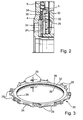
- Fig. 2 shows the friction ring 30 of the Fig. 1 in an enlarged view and in opposite Fig. 1 slightly modified arrangement. Corresponding parts are denoted by the same reference numerals as in Fig. 1 used.
- annular plate 24 is fixed to a rigidly connected to the primary flywheel 4 annular flange 24 1 and the support ring 34 and the plate spring ring 35 between the friction ring 30 and the primary flywheel 4 are arranged so that the annular disc portion 32 of the friction ring 30 in Attachment to the annular shoulder 26 is.
- Fig. 3 shows a perspective view of the friction ring 30 with the lugs 28, via which the rotationally fixed connection of the friction ring 30 takes place with the secondary flywheel and the annular disc part 32, the direction perpendicular to the axis of the annular disc member 32 directed annular disc-shaped friction surfaces 36, 38, in abutment with corresponding Friction surfaces of the annular shoulder 26 and the support ring 34 are.
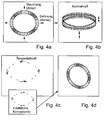
- the darkened areas mean antinodes of the disc with respect to a vibration in the radial direction, wherein in the circumferential direction due to transverse contraction each thickening of a dilution follows, resulting in a change in the normal force according to the figure part b).
- the change in the normal forces leads to changes in the tangential forces, as shown in the figure part c, so that overall results in a dynamic deformation of the disc according to d.
- the annular disc has an unlimited number of eigenmodes, each having a specific shape.
- the radial displacement of the annular disc in such vibration modes has in the circumferential direction m maxima and minima and 2m node lines.
- w A ⁇ ⁇ w B ( ⁇ ) w A ⁇ ⁇ - ⁇ 2 ⁇ m .
- ⁇ is an angle measured in the circumferential direction of the annular disc.
- An analysis using, for example, the ANSYS 10.0 program with QR Damped Modal Analysis shows that the unlimited number of eigenmodes that occur in pairs with the same natural frequency is unstable without attenuation.
- the sources of instability are the axial symmetry of the annular disk, due to which the large amount of paired modes is the same frequency, and the transverse contraction, which is a coupling between the vibrations in the plane of the annular disk and the changes in the normal and causes tangential force.
- Fig. 5 shows in the vertical direction consecutively three different eigenmodes of the annular disc or the friction ring with four, six and eight bellies and each adjacent to the right of the pair mode, the node has where in the left mode are bellies.
- the symmetry of the friction ring 30 or its annular disk part 32, which is present in the circumferential direction, is disturbed to separate the natural frequencies of the coupled modes from one another, as a result of which the force transmission due to transverse contraction is also weakened.
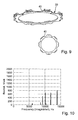
- the disturbance of the cyclic symmetry in the circumferential direction can take place in various ways, for example by variations in the width of the annular disc part, by the formation of holes, etc. Good results are achieved by the fact that Ring disc part 32 recesses 40 are formed, which, as in Fig. 6 shown, along a circumferential angle ⁇ i and their distance in the circumferential direction ⁇ i .
- the recesses 40 may be, for example, axial milled grooves whose depth is advantageously such that the bottom of the recess does not come into contact with the support ring 34 or the annular projection 26.
- the depressions can be formed on one or both sides of the annular disc part 32.
- a depression is already sufficient to achieve a noticeable reduction in noise.
- the instability or the oscillation can be almost completely eliminated, with three wells a possible imbalance can be better eliminated.
- the total circumferential angle over which the depressions extend ie the sum of ⁇ i is advantageously more than 45 degrees, with good results having been achieved at a sum angle of 120 degrees to 180 degrees.
- the width in the circumferential direction of the recesses and the distance in the circumferential direction between the recesses can be optimized such that, for example, in a Q-R Damped Modal analyses with the program ANSYS 10.0 the number of eigenvalues with positive real parts and the maximum value of the real parts is minimized.
- the invention has been described with reference to an example in which an annular disk-shaped component is in sliding friction contact with corresponding mating surfaces on its annular-disc-shaped end or friction surfaces.
- the invention can also be used advantageously for annular discs, which are only on one side in frictional engagement with a counterpart component, wherein the counterpart components or not must necessarily abut over the entire circumference of the annular disk at this or must.
Landscapes
- Engineering & Computer Science (AREA)
- General Engineering & Computer Science (AREA)
- Physics & Mathematics (AREA)
- Acoustics & Sound (AREA)
- Aviation & Aerospace Engineering (AREA)
- Mechanical Engineering (AREA)
- Manufacturing & Machinery (AREA)
- Mechanical Operated Clutches (AREA)
- Braking Arrangements (AREA)
- Pressure Welding/Diffusion-Bonding (AREA)
- Lining Or Joining Of Plastics Or The Like (AREA)
Applications Claiming Priority (1)
| Application Number | Priority Date | Filing Date | Title |
|---|---|---|---|
| DE102007006797 | 2007-02-12 |
Publications (3)
| Publication Number | Publication Date |
|---|---|
| EP1956265A2 true EP1956265A2 (fr) | 2008-08-13 |
| EP1956265A3 EP1956265A3 (fr) | 2010-08-18 |
| EP1956265B1 EP1956265B1 (fr) | 2011-09-21 |
Family
ID=39327328
Family Applications (1)
| Application Number | Title | Priority Date | Filing Date |
|---|---|---|---|
| EP08001020A Not-in-force EP1956265B1 (fr) | 2007-02-12 | 2008-01-21 | Procédé destiné à réduire les oscillations d'un composant essentiellement en forme de disque annulaire et composant en forme de disque annulaire |
Country Status (4)
| Country | Link |
|---|---|
| EP (1) | EP1956265B1 (fr) |
| CN (1) | CN101245816B (fr) |
| AT (1) | ATE525590T1 (fr) |
| DE (1) | DE102008005022A1 (fr) |
Families Citing this family (3)
| Publication number | Priority date | Publication date | Assignee | Title |
|---|---|---|---|---|
| DE102011016787A1 (de) | 2011-03-28 | 2012-10-04 | Schaeffler Technologies Gmbh & Co. Kg | Drehschwingungsdämpfer |
| DE112013005140A5 (de) | 2012-10-25 | 2015-07-16 | Schaeffler Technologies AG & Co. KG | Drehschwingungsdämpfer |
| DE102014211603A1 (de) * | 2014-06-17 | 2015-12-17 | Schaeffler Technologies AG & Co. KG | Zweimassenschwungrad mit Drehmomentbegrenzer |
Family Cites Families (5)
| Publication number | Priority date | Publication date | Assignee | Title |
|---|---|---|---|---|
| US4788884A (en) * | 1985-09-07 | 1988-12-06 | Luk Lamellen Und Kupplungsbau Gmbh | Apparatus for counteracting torsional stresses |
| US5194044A (en) * | 1986-07-05 | 1993-03-16 | Luk Lamellen Und Kupplungsbau Gmbh | Torsional vibration damping apparatus |
| FR2698939B1 (fr) * | 1992-12-08 | 1995-01-20 | Valeo | Amortisseur de torsion, notamment pour véhicule automobile. |
| FR2725003B1 (fr) * | 1994-09-28 | 1997-01-10 | Valeo | Dispositif amortisseur de torsion |
| GB9505750D0 (en) * | 1995-03-21 | 1995-05-10 | Automotive Products Plc | A twin mass flywheel friction damping device |
-
2008
- 2008-01-21 AT AT08001020T patent/ATE525590T1/de active
- 2008-01-21 EP EP08001020A patent/EP1956265B1/fr not_active Not-in-force
- 2008-01-21 DE DE102008005022A patent/DE102008005022A1/de not_active Withdrawn
- 2008-02-13 CN CN2008100096121A patent/CN101245816B/zh not_active Expired - Fee Related
Also Published As
| Publication number | Publication date |
|---|---|
| DE102008005022A1 (de) | 2008-08-14 |
| EP1956265B1 (fr) | 2011-09-21 |
| EP1956265A3 (fr) | 2010-08-18 |
| ATE525590T1 (de) | 2011-10-15 |
| CN101245816A (zh) | 2008-08-20 |
| CN101245816B (zh) | 2012-10-10 |
Similar Documents
| Publication | Publication Date | Title |
|---|---|---|
| EP0521446A2 (fr) | Amortisseur | |
| DE2854050A1 (de) | Vibrationsdaempfer | |
| DE102012204222A1 (de) | Fliehkraftpendeleinrichtung | |
| DE2739583A1 (de) | Torsionsschwingungsdaempfer | |
| DE69507091T2 (de) | Drehmoment-absorbierende Scheibe | |
| DE3439701C2 (fr) | ||
| DE102019118488A1 (de) | Drehschwingungsdämpfer | |
| EP1956265B1 (fr) | Procédé destiné à réduire les oscillations d'un composant essentiellement en forme de disque annulaire et composant en forme de disque annulaire | |
| DE19710918B4 (de) | Verfahren zur Herstellung einer Zusatzmasse für eine Schwungmassenvorrichtung und Schwungmassenvorrichtung mit einer derart hergestellten Zusatzmasse | |
| DE112013002908T5 (de) | Pendeldämpfungsvorrichtung mit stabilisiertem Abrollelement | |
| DE102016220911A1 (de) | Fliehkraftpendeleinrichtung, Drehmomentübertragungseinrichtung und Verfahren zum Montieren und Auswuchten einer Fliehkraftpendeleinrichtung | |
| DE102015120829B4 (de) | Vorrichtung zum Verringern von Vibration für Fahrzeuge | |
| DE102017126796A1 (de) | Drehschwingungsdämpfer | |
| DE102020109676A1 (de) | Drehschwingungsdämpfer sowie Verfahren zur Montage eines Drehschwingungsdämpfers | |
| EP3280930B1 (fr) | Pendule centrifuge | |
| EP3161343B1 (fr) | Pendule centrifuge | |
| DE102017123579A1 (de) | Flanschanordnung für ein Zweimassenschwungrad | |
| WO2016141941A1 (fr) | Amortisseur de vibrations torsionnelles | |
| EP3165785B1 (fr) | Plate d'embrayage pour un dispositif de transmission de couple | |
| EP3146235B1 (fr) | Volant muni d'un pendule centrifuge | |
| DE69709279T2 (de) | Torsionsdämpfer mit Fingern für Getriebeelement, insbesondere Reibungskupplung eines Fahrzeugs | |
| DE102024100833A1 (de) | Rutschkupplung, Drehmomentbegrenzer, Drehschwingungsdämpfer, Blechbauteil und Verfahren zur Herstellung des Blechbauteils der Rutschkupplung | |
| DE10059258A1 (de) | Kupplungsscheibenanordnung | |
| DE2939331A1 (de) | Torsionsschwingungsdaempfer | |
| EP1992836B1 (fr) | Amortisseur de vibrations de torsion |
Legal Events
| Date | Code | Title | Description |
|---|---|---|---|
| PUAI | Public reference made under article 153(3) epc to a published international application that has entered the european phase |
Free format text: ORIGINAL CODE: 0009012 |
|
| AK | Designated contracting states |
Kind code of ref document: A2 Designated state(s): AT BE BG CH CY CZ DE DK EE ES FI FR GB GR HR HU IE IS IT LI LT LU LV MC MT NL NO PL PT RO SE SI SK TR |
|
| AX | Request for extension of the european patent |
Extension state: AL BA MK RS |
|
| PUAL | Search report despatched |
Free format text: ORIGINAL CODE: 0009013 |
|
| AK | Designated contracting states |
Kind code of ref document: A3 Designated state(s): AT BE BG CH CY CZ DE DK EE ES FI FR GB GR HR HU IE IS IT LI LT LU LV MC MT NL NO PL PT RO SE SI SK TR |
|
| AX | Request for extension of the european patent |
Extension state: AL BA MK RS |
|
| 17P | Request for examination filed |
Effective date: 20110218 |
|
| AKX | Designation fees paid |
Designated state(s): AT BE BG CH CY CZ DE DK EE ES FI FR GB GR HR HU IE IS IT LI LT LU LV MC MT NL NO PL PT RO SE SI SK TR |
|
| RAP1 | Party data changed (applicant data changed or rights of an application transferred) |
Owner name: SCHAEFFLER TECHNOLOGIES GMBH & CO. KG |
|
| GRAP | Despatch of communication of intention to grant a patent |
Free format text: ORIGINAL CODE: EPIDOSNIGR1 |
|
| RIC1 | Information provided on ipc code assigned before grant |
Ipc: F16F 15/139 20060101AFI20110405BHEP |
|
| GRAS | Grant fee paid |
Free format text: ORIGINAL CODE: EPIDOSNIGR3 |
|
| GRAA | (expected) grant |
Free format text: ORIGINAL CODE: 0009210 |
|
| AK | Designated contracting states |
Kind code of ref document: B1 Designated state(s): AT BE BG CH CY CZ DE DK EE ES FI FR GB GR HR HU IE IS IT LI LT LU LV MC MT NL NO PL PT RO SE SI SK TR |
|
| REG | Reference to a national code |
Ref country code: GB Ref legal event code: FG4D Free format text: NOT ENGLISH |
|
| REG | Reference to a national code |
Ref country code: CH Ref legal event code: EP |
|
| REG | Reference to a national code |
Ref country code: IE Ref legal event code: FG4D Free format text: LANGUAGE OF EP DOCUMENT: GERMAN |
|
| REG | Reference to a national code |
Ref country code: DE Ref legal event code: R096 Ref document number: 502008004921 Country of ref document: DE Effective date: 20111215 |
|
| REG | Reference to a national code |
Ref country code: NL Ref legal event code: VDEP Effective date: 20110921 |
|
| PG25 | Lapsed in a contracting state [announced via postgrant information from national office to epo] |
Ref country code: LT Free format text: LAPSE BECAUSE OF FAILURE TO SUBMIT A TRANSLATION OF THE DESCRIPTION OR TO PAY THE FEE WITHIN THE PRESCRIBED TIME-LIMIT Effective date: 20110921 Ref country code: HR Free format text: LAPSE BECAUSE OF FAILURE TO SUBMIT A TRANSLATION OF THE DESCRIPTION OR TO PAY THE FEE WITHIN THE PRESCRIBED TIME-LIMIT Effective date: 20110921 Ref country code: FI Free format text: LAPSE BECAUSE OF FAILURE TO SUBMIT A TRANSLATION OF THE DESCRIPTION OR TO PAY THE FEE WITHIN THE PRESCRIBED TIME-LIMIT Effective date: 20110921 Ref country code: NO Free format text: LAPSE BECAUSE OF FAILURE TO SUBMIT A TRANSLATION OF THE DESCRIPTION OR TO PAY THE FEE WITHIN THE PRESCRIBED TIME-LIMIT Effective date: 20111221 Ref country code: SE Free format text: LAPSE BECAUSE OF FAILURE TO SUBMIT A TRANSLATION OF THE DESCRIPTION OR TO PAY THE FEE WITHIN THE PRESCRIBED TIME-LIMIT Effective date: 20110921 |
|
| LTIE | Lt: invalidation of european patent or patent extension |
Effective date: 20110921 |
|
| PG25 | Lapsed in a contracting state [announced via postgrant information from national office to epo] |
Ref country code: SI Free format text: LAPSE BECAUSE OF FAILURE TO SUBMIT A TRANSLATION OF THE DESCRIPTION OR TO PAY THE FEE WITHIN THE PRESCRIBED TIME-LIMIT Effective date: 20110921 Ref country code: LV Free format text: LAPSE BECAUSE OF FAILURE TO SUBMIT A TRANSLATION OF THE DESCRIPTION OR TO PAY THE FEE WITHIN THE PRESCRIBED TIME-LIMIT Effective date: 20110921 Ref country code: GR Free format text: LAPSE BECAUSE OF FAILURE TO SUBMIT A TRANSLATION OF THE DESCRIPTION OR TO PAY THE FEE WITHIN THE PRESCRIBED TIME-LIMIT Effective date: 20111222 Ref country code: CY Free format text: LAPSE BECAUSE OF FAILURE TO SUBMIT A TRANSLATION OF THE DESCRIPTION OR TO PAY THE FEE WITHIN THE PRESCRIBED TIME-LIMIT Effective date: 20110921 |
|
| RAP2 | Party data changed (patent owner data changed or rights of a patent transferred) |
Owner name: SCHAEFFLER TECHNOLOGIES AG & CO. KG |
|
| REG | Reference to a national code |
Ref country code: CH Ref legal event code: PFA Owner name: SCHAEFFLER TECHNOLOGIES AG & CO. KG Free format text: SCHAEFFLER TECHNOLOGIES GMBH & CO. KG#INDUSTRIESTRASSE 1-3#91074 HERZOGENAURACH (DE) -TRANSFER TO- SCHAEFFLER TECHNOLOGIES AG & CO. KG#INDUSTRIESTRASSE 1-3#91074 HERZOGENAURACH (DE) |
|
| REG | Reference to a national code |
Ref country code: IE Ref legal event code: FD4D |
|
| PG25 | Lapsed in a contracting state [announced via postgrant information from national office to epo] |
Ref country code: SK Free format text: LAPSE BECAUSE OF FAILURE TO SUBMIT A TRANSLATION OF THE DESCRIPTION OR TO PAY THE FEE WITHIN THE PRESCRIBED TIME-LIMIT Effective date: 20110921 Ref country code: CZ Free format text: LAPSE BECAUSE OF FAILURE TO SUBMIT A TRANSLATION OF THE DESCRIPTION OR TO PAY THE FEE WITHIN THE PRESCRIBED TIME-LIMIT Effective date: 20110921 Ref country code: IE Free format text: LAPSE BECAUSE OF FAILURE TO SUBMIT A TRANSLATION OF THE DESCRIPTION OR TO PAY THE FEE WITHIN THE PRESCRIBED TIME-LIMIT Effective date: 20110921 Ref country code: IS Free format text: LAPSE BECAUSE OF FAILURE TO SUBMIT A TRANSLATION OF THE DESCRIPTION OR TO PAY THE FEE WITHIN THE PRESCRIBED TIME-LIMIT Effective date: 20120121 |
|
| PG25 | Lapsed in a contracting state [announced via postgrant information from national office to epo] |
Ref country code: RO Free format text: LAPSE BECAUSE OF FAILURE TO SUBMIT A TRANSLATION OF THE DESCRIPTION OR TO PAY THE FEE WITHIN THE PRESCRIBED TIME-LIMIT Effective date: 20110921 Ref country code: PT Free format text: LAPSE BECAUSE OF FAILURE TO SUBMIT A TRANSLATION OF THE DESCRIPTION OR TO PAY THE FEE WITHIN THE PRESCRIBED TIME-LIMIT Effective date: 20120123 Ref country code: IT Free format text: LAPSE BECAUSE OF FAILURE TO SUBMIT A TRANSLATION OF THE DESCRIPTION OR TO PAY THE FEE WITHIN THE PRESCRIBED TIME-LIMIT Effective date: 20110921 Ref country code: NL Free format text: LAPSE BECAUSE OF FAILURE TO SUBMIT A TRANSLATION OF THE DESCRIPTION OR TO PAY THE FEE WITHIN THE PRESCRIBED TIME-LIMIT Effective date: 20110921 Ref country code: EE Free format text: LAPSE BECAUSE OF FAILURE TO SUBMIT A TRANSLATION OF THE DESCRIPTION OR TO PAY THE FEE WITHIN THE PRESCRIBED TIME-LIMIT Effective date: 20110921 Ref country code: PL Free format text: LAPSE BECAUSE OF FAILURE TO SUBMIT A TRANSLATION OF THE DESCRIPTION OR TO PAY THE FEE WITHIN THE PRESCRIBED TIME-LIMIT Effective date: 20110921 |
|
| PLBE | No opposition filed within time limit |
Free format text: ORIGINAL CODE: 0009261 |
|
| STAA | Information on the status of an ep patent application or granted ep patent |
Free format text: STATUS: NO OPPOSITION FILED WITHIN TIME LIMIT |
|
| BERE | Be: lapsed |
Owner name: SCHAEFFLER TECHNOLOGIES G.M.B.H. & CO. KG Effective date: 20120131 |
|
| PG25 | Lapsed in a contracting state [announced via postgrant information from national office to epo] |
Ref country code: DK Free format text: LAPSE BECAUSE OF FAILURE TO SUBMIT A TRANSLATION OF THE DESCRIPTION OR TO PAY THE FEE WITHIN THE PRESCRIBED TIME-LIMIT Effective date: 20110921 |
|
| 26N | No opposition filed |
Effective date: 20120622 |
|
| PG25 | Lapsed in a contracting state [announced via postgrant information from national office to epo] |
Ref country code: MC Free format text: LAPSE BECAUSE OF NON-PAYMENT OF DUE FEES Effective date: 20120131 |
|
| REG | Reference to a national code |
Ref country code: CH Ref legal event code: PL |
|
| GBPC | Gb: european patent ceased through non-payment of renewal fee |
Effective date: 20120121 |
|
| REG | Reference to a national code |
Ref country code: DE Ref legal event code: R097 Ref document number: 502008004921 Country of ref document: DE Effective date: 20120622 Ref country code: DE Ref legal event code: R081 Ref document number: 502008004921 Country of ref document: DE Owner name: SCHAEFFLER TECHNOLOGIES AG & CO. KG, DE Free format text: FORMER OWNER: SCHAEFFLER TECHNOLOGIES GMBH & CO. KG, 91074 HERZOGENAURACH, DE Effective date: 20120828 Ref country code: DE Ref legal event code: R081 Ref document number: 502008004921 Country of ref document: DE Owner name: SCHAEFFLER TECHNOLOGIES GMBH & CO. KG, DE Free format text: FORMER OWNER: SCHAEFFLER TECHNOLOGIES GMBH & CO. KG, 91074 HERZOGENAURACH, DE Effective date: 20120828 |
|
| PG25 | Lapsed in a contracting state [announced via postgrant information from national office to epo] |
Ref country code: LI Free format text: LAPSE BECAUSE OF NON-PAYMENT OF DUE FEES Effective date: 20120131 Ref country code: CH Free format text: LAPSE BECAUSE OF NON-PAYMENT OF DUE FEES Effective date: 20120131 Ref country code: GB Free format text: LAPSE BECAUSE OF NON-PAYMENT OF DUE FEES Effective date: 20120121 |
|
| PG25 | Lapsed in a contracting state [announced via postgrant information from national office to epo] |
Ref country code: BE Free format text: LAPSE BECAUSE OF NON-PAYMENT OF DUE FEES Effective date: 20120131 |
|
| PG25 | Lapsed in a contracting state [announced via postgrant information from national office to epo] |
Ref country code: ES Free format text: LAPSE BECAUSE OF FAILURE TO SUBMIT A TRANSLATION OF THE DESCRIPTION OR TO PAY THE FEE WITHIN THE PRESCRIBED TIME-LIMIT Effective date: 20120101 |
|
| PG25 | Lapsed in a contracting state [announced via postgrant information from national office to epo] |
Ref country code: BG Free format text: LAPSE BECAUSE OF FAILURE TO SUBMIT A TRANSLATION OF THE DESCRIPTION OR TO PAY THE FEE WITHIN THE PRESCRIBED TIME-LIMIT Effective date: 20111221 |
|
| PG25 | Lapsed in a contracting state [announced via postgrant information from national office to epo] |
Ref country code: MT Free format text: LAPSE BECAUSE OF FAILURE TO SUBMIT A TRANSLATION OF THE DESCRIPTION OR TO PAY THE FEE WITHIN THE PRESCRIBED TIME-LIMIT Effective date: 20110921 |
|
| REG | Reference to a national code |
Ref country code: AT Ref legal event code: MM01 Ref document number: 525590 Country of ref document: AT Kind code of ref document: T Effective date: 20130121 |
|
| REG | Reference to a national code |
Ref country code: DE Ref legal event code: R081 Ref document number: 502008004921 Country of ref document: DE Owner name: SCHAEFFLER TECHNOLOGIES AG & CO. KG, DE Free format text: FORMER OWNER: SCHAEFFLER TECHNOLOGIES AG & CO. KG, 91074 HERZOGENAURACH, DE Effective date: 20140214 Ref country code: DE Ref legal event code: R081 Ref document number: 502008004921 Country of ref document: DE Owner name: SCHAEFFLER TECHNOLOGIES GMBH & CO. KG, DE Free format text: FORMER OWNER: SCHAEFFLER TECHNOLOGIES AG & CO. KG, 91074 HERZOGENAURACH, DE Effective date: 20140214 |
|
| PG25 | Lapsed in a contracting state [announced via postgrant information from national office to epo] |
Ref country code: TR Free format text: LAPSE BECAUSE OF FAILURE TO SUBMIT A TRANSLATION OF THE DESCRIPTION OR TO PAY THE FEE WITHIN THE PRESCRIBED TIME-LIMIT Effective date: 20110921 |
|
| PG25 | Lapsed in a contracting state [announced via postgrant information from national office to epo] |
Ref country code: LU Free format text: LAPSE BECAUSE OF NON-PAYMENT OF DUE FEES Effective date: 20120121 Ref country code: AT Free format text: LAPSE BECAUSE OF NON-PAYMENT OF DUE FEES Effective date: 20130121 |
|
| PG25 | Lapsed in a contracting state [announced via postgrant information from national office to epo] |
Ref country code: HU Free format text: LAPSE BECAUSE OF FAILURE TO SUBMIT A TRANSLATION OF THE DESCRIPTION OR TO PAY THE FEE WITHIN THE PRESCRIBED TIME-LIMIT Effective date: 20080121 |
|
| REG | Reference to a national code |
Ref country code: DE Ref legal event code: R081 Ref document number: 502008004921 Country of ref document: DE Owner name: SCHAEFFLER TECHNOLOGIES AG & CO. KG, DE Free format text: FORMER OWNER: SCHAEFFLER TECHNOLOGIES GMBH & CO. KG, 91074 HERZOGENAURACH, DE Effective date: 20150223 |
|
| REG | Reference to a national code |
Ref country code: FR Ref legal event code: PLFP Year of fee payment: 9 |
|
| REG | Reference to a national code |
Ref country code: FR Ref legal event code: PLFP Year of fee payment: 10 |
|
| REG | Reference to a national code |
Ref country code: FR Ref legal event code: PLFP Year of fee payment: 11 |
|
| PGFP | Annual fee paid to national office [announced via postgrant information from national office to epo] |
Ref country code: FR Payment date: 20190130 Year of fee payment: 12 |
|
| PGFP | Annual fee paid to national office [announced via postgrant information from national office to epo] |
Ref country code: DE Payment date: 20190401 Year of fee payment: 12 |
|
| REG | Reference to a national code |
Ref country code: DE Ref legal event code: R119 Ref document number: 502008004921 Country of ref document: DE |
|
| PG25 | Lapsed in a contracting state [announced via postgrant information from national office to epo] |
Ref country code: FR Free format text: LAPSE BECAUSE OF NON-PAYMENT OF DUE FEES Effective date: 20200131 Ref country code: DE Free format text: LAPSE BECAUSE OF NON-PAYMENT OF DUE FEES Effective date: 20200801 |
|
| P01 | Opt-out of the competence of the unified patent court (upc) registered |
Effective date: 20230523 |