EP1957246B1 - Verfahren zur herstellung einer rohrleitung aus zementmaterial mit einem kreisförmigen abschnitt - Google Patents
Verfahren zur herstellung einer rohrleitung aus zementmaterial mit einem kreisförmigen abschnitt Download PDFInfo
- Publication number
- EP1957246B1 EP1957246B1 EP06840960A EP06840960A EP1957246B1 EP 1957246 B1 EP1957246 B1 EP 1957246B1 EP 06840960 A EP06840960 A EP 06840960A EP 06840960 A EP06840960 A EP 06840960A EP 1957246 B1 EP1957246 B1 EP 1957246B1
- Authority
- EP
- European Patent Office
- Prior art keywords
- cement
- mould
- product
- phase
- extrusion
- Prior art date
- Legal status (The legal status is an assumption and is not a legal conclusion. Google has not performed a legal analysis and makes no representation as to the accuracy of the status listed.)
- Not-in-force
Links
Images


Classifications
-
- B—PERFORMING OPERATIONS; TRANSPORTING
- B28—WORKING CEMENT, CLAY, OR STONE
- B28B—SHAPING CLAY OR OTHER CERAMIC COMPOSITIONS; SHAPING SLAG; SHAPING MIXTURES CONTAINING CEMENTITIOUS MATERIAL, e.g. PLASTER
- B28B21/00—Methods or machines specially adapted for the production of tubular articles
- B28B21/92—Methods or apparatus for treating or reshaping
- B28B21/98—Methods or apparatus for treating or reshaping for reshaping, e.g. by means of reshape moulds
-
- B—PERFORMING OPERATIONS; TRANSPORTING
- B28—WORKING CEMENT, CLAY, OR STONE
- B28B—SHAPING CLAY OR OTHER CERAMIC COMPOSITIONS; SHAPING SLAG; SHAPING MIXTURES CONTAINING CEMENTITIOUS MATERIAL, e.g. PLASTER
- B28B21/00—Methods or machines specially adapted for the production of tubular articles
- B28B21/52—Methods or machines specially adapted for the production of tubular articles by extruding
Definitions
- the present invention relates to a process for the production of piping made of a cementitious material having a circular section.
- the present invention derives from the field of extrusion processes of tubular-shaped end-products made of a cementitious material.
- the present invention relates to a process for the production by extrusion of piping made of fibre-cement with a circular section and fine thickness, suitable for the channelling of liquids and gases at atmospheric operating pressure or slightly higher.
- the present invention also allows the production of end-products with a circular section, for applications in the building and industrial sector such as for example permanent formworks and pillars.
- Typical pipes made of cementitious material are pipes made of concrete, reinforced concrete, asbestos cement and fibre-cement without asbestos.
- the most widely-used plastic materials are PVC, polyethylene, polypropylene and glass-resin.
- the diameters available for the pipes can vary and are divided according to the various types of use.
- German patent DE544046 discloses a method for consolidating and simultaneous dehydrate a preformed, water-containing asbestos-cement pipe, characterized in that the preformed pipe is inserted in a mould, which possibly has a circular section, and subjected to a roll pressure from inside outward simultaneously along the whole tube length.
- pipes made of fibre-cement having a fine thickness are also known, mainly produced by means of the so-called Mazza process (deriving from the Hatschek technology).
- the material used par excellence was asbestos-cement, recently substituted for environmental reasons by so-called fibre-cement.
- the Mazza/Hatschek process cementitious compositions are used, containing cement, process fibres and reinforcing fibres (both synthetic and natural) and other secondary additives.
- the products obtained have high mechanical characteristics, they are extremely compact and have low thicknesses.
- the extrusion can be effected with batch or intermittent plug/cylinder systems ("plug extrusion", or “capillary extrusion"), or with continuous screw/cylinder systems.
- plug extrusion or "capillary extrusion”
- continuous screw/cylinder systems With the exception of ceramic stoneware, in all the other cases the extrusion is carried out horizontally.
- ceramic stoneware in fact, thanks to the high thicknesses of the pipes in relation to their length (normally two metres), there is a rigidity in the fresh state of the pipes which does not cause deformation or distortion.
- extruders having two consecutive screws, intervalled by a vacuum chamber to facilitate the pressurized extrusion of pastes.
- extruder models normally used in the brick industry.
- the Japanese patent JP-A-01 160612 discloses a process for the production of piping made of cementitious material according to the preamble of claim 1, having a smooth surface and omitting deformation and cavity defect after forming comprising the extrusion of a cement mortar tube, its cutting into desired dimension and its fittingly insertion into a forming die which is pre-heated at 60-120°C.
- a forming body pre-heated at the same temperature as that of the of the forming die is inserted under pressure into the cement mortar tube so that the tube is consequently heated and compressed with the inner peripheral surface of the forming die and the outer peripheral surface of the forming body.
- Pipes produced by extrusion have the problem at the outlet of the die of maintaining their form as, due to their weight and low thickness, they bend over themselves losing their circular shape.
- vacuum percentage refers to the percentage ratio between the empty surface and the full surface of the tubular product. The greater this percentage, especially in the presence of large dimensional end-products, the more critical the problem of maintaining the form becomes.
- This problem is not limited to the field of cement-based pipes but also relates to pipes made of plastic materials such as for example PVC and PE pipes.
- the problem has at least been partially overcome by passing the pipe into a cooled calibrator which, by causing the rapid hardening of the plastic, also ensures its circular form.
- this characteristic is also defined as the "green strength" of the extruded product, or also "form stability”.
- Green strength or “form stability”, in the present invention relate to the capacity of the neo-extruded end-product of maintaining its own shape (or geometry) immediately after leaving the extruder die.
- the possibility of obtaining an adequate green strength of the extruded product is typically related to various composition or process parameters, such as: compactness of the solid components; the low water/solid ratio of the paste also correlated with the mechanical resistance of the material; the extrusion pressure; the possibility of using a heated die; the possibility of using chemical compounds capable, of being thermally activated to harden the outgoing material.
- One of the objectives of the present invention therefore consists in providing a process for the production of piping made of cementitious material having a circular section which allows to maintain substantially the form of the end-product immediately after the extrusion phase.
- a further objective of the present invention consists in providing a process which allows the production of piping made of fibre-cement with a fine thickness which stably preserves its circular form after extrusion.
- Another aspect of the present invention consists in providing a method for preserving, at the outlet of the die, the circular form of the fibre-cement piping produced by extrusion.
- a process is provided for the production of a piping made of cementitious material having a circular section in accordance with claim 1.
- the cement-based end-product or piping having a circular geometry is subjected after extrusion to rolling by rotation inside a tubular counter-mould.
- the rolling movement phase suitable for maintaining the circularity of the piping, is conveniently effected in an alternating direction and prolonged until a hardening degree is reached, which ensures the preservation of the circular form.
- the moving phase begins at the outlet of the extruder and comprises the rotation of the piping in an alternating direction in a tubular counter-mould, conveniently positioned directly in contact with the extruder die.
- the piping leaving the die therefore finds a tunnel, consisting of the counter-mould, in which it passes for a pre-established length until the cutting phase and subsequent transferral.
- Said counter-mould is typically a pipe having a circular section made of a metallic or plastic material, for example PVC or PE.
- the neo-extruded pipe made of cementitious material is capable of passing through this mould without the help of pullers and/or external movements, for example for lengths up to 6 metres, partly adhering to the walls of the mould, especially below.
- the piping-tubular counter-mould system is cut and sent to a rotating roll system in an alternating direction.
- the extruded pipe has a deformed geometry with a loss of its circular form.
- the rolling phase allows the perfect recovery of the circular form.
- the hardening starting time of the cement-based material is variable and is typically about 2 hours after extrusion.
- the piping-tubular counter-mould combination is conveniently maintained in alternating rotation at a rate conveniently ranging from 0.2 rpm to 10 rpm for a time varying from 2 to 5 hours depending on the dimensions of the pipe.
- the velocity range is preferably from 0.4 to 7.5 rpm, more preferably from 0.4 to 2 rpm, until a hardening degree is reached which is such as to ensure the preservation of the form.
- the hardening of the pipes can take place within a time conveniently ranging from 30 minutes to 3 hours, more preferably from 1 to 2 hours.
- the cement pipe is then extracted from the tubular counter-mould and sent to the final curing system.
- the diameter of the counter-mould which must be greater than the outer diameter of the extruded pipe, is advantageously not excessively greater than the extruded piping in order not to jeopardize the final performances of the end-product. It has been observed that it is preferable to have a tolerance for the counter-mould with respect to its inner diameter ranging from 0.4 to 3% and more preferably from 0.8 to 2% more with respect to the outer diameter of the extruded pipe.
- the process of the invention allows pipes to be obtained, having a regular circular form, with a typical length of up to three metres, practically without cracks caused by shrinkage or mechanical stress, with high mechanical performances.
- the process of the invention envisages the use of an automatic calibration plant comprising a series of calibrating moulds in order to increase the production rates and reduce the withdrawal times from the counter-mould.
- the cement pipe leaves the extruder and advances, passing into the first calibrator of a pre-established length; said calibrator is supported by a series of wheels which transmit a self-rotating movement.
- the pipe When the pipe has reached the end of the calibrator, it is cut and the calibrator begins to rotate at a rate conveniently varying from 1 to 100 rpm, preferably from 5 to 75 rpm, more preferably from 10 to 30 rpm.
- the rotation transmits a centrifugal force to the cement pipe and compels it to adhere to the walls of the calibrator, maintaining its circular form.
- the first calibrator is moved from the drawplate, leaving room for a second calibrator in front of the extruder head to receive the second pipe; the same occurs for the other calibrators present.
- an extraction system comprising a pressurized cylinder for extracting the rigid pipe; a catenary system then conveys the empty calibrator downstream of the extruder to repeat the cycle.
- This system is extremely versatile, in relation to the diameters to be obtained as it consists of interchangeable moulds of various sizes positioned inside the calibration plant.
- the pipes are subjected to a final curing cycle which can consist either of treatment with water, at either room temperature or under heating, preferably not higher than 80°C, or of treatment in static climatic chambers and/or in tunnels on line under controlled temperature conditions, preferably at a maximum temperature of 50°C, and humidity.
- a final curing cycle which can consist either of treatment with water, at either room temperature or under heating, preferably not higher than 80°C, or of treatment in static climatic chambers and/or in tunnels on line under controlled temperature conditions, preferably at a maximum temperature of 50°C, and humidity.
- the piping obtained with the process of the invention is based on cementitious material or fibre-cement, the latter term comprising materials based on cement containing reinforcing fibre of the natural or synthetic type.
- the process of the invention is particularly suitable for the production of pipes with a circular geometry and fine thickness, typically having a percentage of empty section higher than 60%, preferably higher than 70%.
- a higher vacuum percentage corresponds, with the same nominal diameter, to a greater lightness of the pipe which, for a same malt in fibre-cement composition, in turn corresponds to a lower cost per linear meter of product, as indicated in Table 1.
- the fine thickness referred to in this case is, for the same nominal diameter, lower than that of a pipe made of reinforced or non-reinforced concrete, of the traditional type, or ceramic stoneware.
- the process of the invention typically allows an end-product having a circular section to be obtained, such as pipes, joints and accessories for gravity systems according to the regulation UNI EN 588-1 and for discharge systems for buildings in accordance with the regulation UNI EN 12763.
- the pipes having a circular section obtained with the process of the invention are used in numerous applications sectors, for example in discharge systems, such as sewage disposal, or in drainage systems, and also in pressurized applications or in other types of liquid or gas channelling, at atmospheric operating pressure or slightly higher, or as permanent formworks, for the construction of circular pillars or other cylindrical elements for the building industry.
- FIG. 1 this schematically illustrates the preliminary phases of an embodiment of the process 1 for the production of piping having a circular section made of cementitious material.
- a mixer 2 is fed with:
- the components in solid phase are then mixed in a mixer typically of the intensive type 2 for a time preferably ranging from 1 to 5 minutes, in relation to the characteristics of the mixer and outside temperature until a homogeneous mixture is obtained.
- the liquid components, comprising water, are then added, and the mixing is prolonged for a time typically ranging from 1 to 5 minutes in relation to the characteristics of the mixer and outside temperature.
- the mixture can be in different semi-solid forms varying from wet powder to small pellets or in the form of a paste.
- the system thus obtained is preferably collected in an intermediate collection box, before being sent by transporting means to a pasting machine or homogenizing mixer 6.
- This apparatus 6 has the function of transforming the wet powder, obtained in the mixing phase, into a paste by the application of a high shear stress.
- the semi-fluid system obtained in the form of a paste is collected in a box and sent on belts for feeding an extruder.
- the extruder is preferably of the twin-screw type in series, for example of the type produced by the company Haendle.
- the twin-screw extruder is equipped for example with two screws arranged orthogonally with respect to each other, of which the second screw 8, which is horizontal, typically having a diameter of 350 mm, is suitable for compacting the material also at high pressures.
- Said extruder is particularly suitable for high viscosity materials and which produce considerable friction as cementitious materials.
- the first screw, 7, which is vertical, is used for the loading of the material, the second horizontally 8 for the actual drawing phase and, in correspondence with the draw-plate, a typical maximum internal pressure of 50 bars can be reached, preferably about 40 bars; between the two areas, there is a chamber for creating a vacuum in order to obtain the maximum compacting of the material for a good surface finishing of the end-product.
- the extrusion phase is preferably effected under controlled temperature conditions, typically below room temperature, by means of a cooling system, to ensure a good processability of the pastes thus slowing down the hydration kinetics of the cement.
- the pipe leaving the extrusion die passes into a circular mould made of a plastic or metallic material 9, conveniently positioned in contact with the die of the extruder.
- the extruded substrate is cut and sent, with its mould, to a roll system rotating in an alternating direction.
- the pipes obtained can be subjected to a final curing cycle for example by treatment with water at room temperature or heated, or for treatment in static climatic chambers and/or in tunnels on line with controlled temperature (maximum 50°C) and humidity conditions.
- the pipe is subsequently sent to the final storage phase.
- Figure 2 illustrates a tubular counter-mould 10, situated directly in contact with the die of an extruder 11.
- the neo-extruded tubular end-product 12 leaving the die of the extruder 11 is conveyed into the tubular counter-mould 10.
- the pipe 12 made of a cementitious material passes through said mould 10 without the help of pullers and/or external moving and after reaching the desired length, the pipe is cut and sent with its mould 10 to a pipe moving system by means of rotation.
- Figure 3 illustrates an embodiment of a rolling phase according to a process of the background art which utilizes a roll moving system of the combined piping-tubular counter-mould unit.
- This phase is preferably initiated within 30 minutes of extrusion.
- the rolling phase on rolls allows the perfect recovery of the circularity of the extruded product.
- the combination of piping 12 - counter-mould 10, is kept in alternating rotation at a minimum rate of 0.2 rpm and a maximum rate of 10 rpm (for rolls of the anti-ovalization roller having a diameter of about 220 mm - this velocity range can vary in relation to the diameter of the calibrator rolls and distance of the axes of the rolls themselves) for a time conveniently varying from 2 to 3 hours, until a hardening degree is reached, which is such as to ensure the preservation of the circular geometry of the piping.
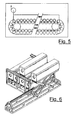
- FIGS. 4 and 5 these schematically show the functioning with the hot air flow lines of an embodiment of the rolling system adopted by an anti-ovalization roller and also the supply system of the moulds downstream of the extruder.
- This system allows pipes having a regular circular form to be obtained, and a length of up to three meters, without cracks due to shrinkage or mechanical stress, with final mechanical performances about 50% higher than the value obtained with the use of the methods of the known art.
- Figure 6 illustrates another embodiment of the system illustrated in figures 4 and 5 which envisages an automatic calibration plant comprising a series of calibrator moulds.
- an automatic calibration plant comprising 6 calibrator moulds. This number of calibrators is purely illustrative as it is associated with the hourly productivity of the extrusion plant.
- the cement piping leaves the extruder and advances, passing into the first calibrator of a pre-established length; said calibrator is supported by a series of wheels which transmit a self-rotation movement.
- the calibrator begins to rotate at a varying rate, for example from 1 to 100 rpm, preferably from 5 to 75 rpm, more preferably from 10 to 30 rpm.
- the rotation transmits a centrifugal force to the cement pipe which compels it to adhere to the walls of the calibrator, maintaining its circular form.
- a heating system is positioned on the outside of the calibrator, which, by heating the cement product, accelerates the hardening process.
- the first calibrator is moved from the draw-plate, leaving room for a second calibrator in front of the extruder head to receive the second pipe; the same occurs for the other 4 calibrators present.
- an extraction system with a pressurized cylinder for extracting the rigid pipe; a catenary system then takes the empty calibrator back downstream of the extruder to repeat the cycle.
- This system is extremely versatile, in relation to the diameters to be obtained as it consists of interchangeable moulds of various sizes situated inside the calibration plant.
- Pipes were produced with the process according to the invention, all corresponding to the geometrical and performance requisites required by the regulation UNI EN 588-1 and UNI EN 12763.
- the pipes had an average thickness of 12.5 mm (DN 200mm per pipe).
- the tolerances with respect to the internal diameter abundantly fall within those specified by the regulation UNI EN 588-1 for DN ⁇ 1200( ⁇ 4.5 mm).
- the pipes thus produced had crush resistance values of 25 KN/ml above the value indicated for said diameters (DN 200 mm), respectively 18 KN/ml for pipes of group 90 (load for unitary internal surface 90 KN/m 2 ) and 24 KN/ml for group 120 of greater commercial interest.
Landscapes
- Engineering & Computer Science (AREA)
- Manufacturing & Machinery (AREA)
- Chemical & Material Sciences (AREA)
- Ceramic Engineering (AREA)
- Mechanical Engineering (AREA)
- Rigid Pipes And Flexible Pipes (AREA)
- Press-Shaping Or Shaping Using Conveyers (AREA)
- Curing Cements, Concrete, And Artificial Stone (AREA)
- Manufacturing Of Tubular Articles Or Embedded Moulded Articles (AREA)
- Devices For Post-Treatments, Processing, Supply, Discharge, And Other Processes (AREA)
Claims (9)
- Verfahren (1) zur Herstellung einer Rohrleitung aus Zementmaterial mit einem kreisförmigen Abschnitt und einer geringen Dicke durch Extrusion einer Masse auf Zementbasis, dadurch gekennzeichnet, dass es eine Stufe zur Walzung der neu extrudierten Rohrleitung (12) im Innern einer rohrförmigen Form (9) umfasst, wobei eine Zentrifugalkraft auf die neu extrudierte Rohrleitung (12) übertragen wird, die ihre kreisförmige Form beibehält, bis der Aushärtungsgrad des Zementmaterials erreicht ist und dadurch gekennzeichnet, dass die rohrförmige Form (9) mindestens eine automatische Kalibriereinrichtung umfasst, die mindestens zwei Kalibratorformen umfasst.
- Verfahren (1) nach Anspruch 1, dadurch gekennzeichnet, dass die Rohrleitung mit kreisförmigen Abschnitt einen Vakuumprozentsatz des Abschnitts von mehr als 60% aufweist.
- Verfahren (1) nach Anspruch 2, dadurch gekennzeichnet, dass der Vakuumprozentsatz des Abschnitts mehr als 70% beträgt.
- Verfahren (1) nach ingerdeinem Anspruch von 1 bis 3, dadurch gekennzeichnet, dass die Rohrleitung aus Faserzement besteht.
- Verfahren (1) nach Anspruch 1, dadurch gekennzeichnet, dass die automatische Kalibriereinrichtung Heizmittel zur direkten Beheizung der Kalibratorform umfasst, die das extrudierte Zementendprodukt enthält.
- Verfahren (1) nach Anspruch 5, dadurch gekennzeichnet, dass die Heizmittel mindestens einen Infrarot-Strahler umfassen.
- Verfahren (1) nach Anspruch 6, dadurch gekennzeichnet, dass die automatische Kalibriereinrichtung eine Reihe von Rädern für die Eigenrotation der Kalibratorform umfasst.
- Verfahren (1) nach Anspruch 7, dadurch gekennzeichnet, dass die Kombination aus dem neu extrudierten Rohr (12) und der Kalibratorform bei einer Geschwindigkeit im Bereich von 1 rpm bis 100 rpm, vorzugsweise 5 bis 75 rpm, in Rotation gehalten wird.
- Verfahren (1) nach Anspruch 1, umfassend:- eine Stufe zum Mischen der Mischung auf Zementbasis mit Wasser, um ein nasses Pulver auf Zementbasis herzustellen;- eine Stufe zur Homogenisierung des nassen Pulvers in einer Anteigmaschine (6), um eine extrudierbare Masse auf Zementbasis zu erzeugen;- eine Stufe zur Extrusion der Masse auf Zementbasis in einem Extruder (11), um ein Endprodukt (12) auf Zementbasis mit einem im Wesentlichen kreisförmigen Abschnitt zu erzeugen;- eine Stufe des Fließens des Zementprodukts (12) mit einem im Wesentlichen kreisförmigen Abschnitt im Innern einer rohrförmigen Form (9), die nahe der Düse des Extruders (11) positioniert ist, um eine Kombination aus Endprodukt und rohrförmiger Form zu bilden;- eine Schneidstufe des Systems aus Endprodukt und rohrförmiger Form;- eine Stufe zur Walzung des Systems aus Endprodukt und rohrförmiger Form, bei der eine Zentrifugalkraft auf das neu extrudierte Rohr (12) übertragen wird, wodurch die kreisförmige Form des Produkts erhalten bleibt, bis der Aushärtungsgrad des Zementmaterials erreicht ist.
Applications Claiming Priority (2)
| Application Number | Priority Date | Filing Date | Title |
|---|---|---|---|
| IT002356A ITMI20052356A1 (it) | 2005-12-09 | 2005-12-09 | Processo per la produzione di tubazioni in materiale cementizio a sezione circolare |
| PCT/EP2006/011809 WO2007065699A1 (en) | 2005-12-09 | 2006-12-06 | Process for the production of piping made of a cementitious material having a circular section |
Publications (2)
| Publication Number | Publication Date |
|---|---|
| EP1957246A1 EP1957246A1 (de) | 2008-08-20 |
| EP1957246B1 true EP1957246B1 (de) | 2011-04-20 |
Family
ID=37847058
Family Applications (1)
| Application Number | Title | Priority Date | Filing Date |
|---|---|---|---|
| EP06840960A Not-in-force EP1957246B1 (de) | 2005-12-09 | 2006-12-06 | Verfahren zur herstellung einer rohrleitung aus zementmaterial mit einem kreisförmigen abschnitt |
Country Status (13)
| Country | Link |
|---|---|
| US (1) | US8070997B2 (de) |
| EP (1) | EP1957246B1 (de) |
| CN (1) | CN101356046B (de) |
| AT (1) | ATE506159T1 (de) |
| CA (1) | CA2631225C (de) |
| DE (1) | DE602006021464D1 (de) |
| EG (1) | EG24906A (de) |
| ES (1) | ES2365253T3 (de) |
| IT (1) | ITMI20052356A1 (de) |
| MA (1) | MA30030B1 (de) |
| RU (1) | RU2431563C2 (de) |
| WO (1) | WO2007065699A1 (de) |
| ZA (1) | ZA200804862B (de) |
Families Citing this family (5)
| Publication number | Priority date | Publication date | Assignee | Title |
|---|---|---|---|---|
| ITMI20061594A1 (it) | 2006-08-08 | 2008-02-09 | Italcementi Spa | Nuovi manufatti cementizi prefabbricati con attivita' fotocatalitica |
| US10195764B2 (en) * | 2012-03-09 | 2019-02-05 | Halliburton Energy Services, Inc. | Set-delayed cement compositions comprising pumice and associated methods |
| CN102689357A (zh) * | 2012-06-11 | 2012-09-26 | 杭州小米环境科技有限公司 | 挤压式耐火高强排气道制作设备及工艺 |
| AU2014402282A1 (en) | 2014-07-29 | 2016-08-25 | 161508 Canada Inc. | System and process for molding of parts made of fiber cement |
| CN114919059B (zh) * | 2022-06-15 | 2022-12-09 | 吉林市吉能电力技术有限公司 | 一种用于环形混凝土构件生产的离心挤压成形的装置 |
Family Cites Families (13)
| Publication number | Priority date | Publication date | Assignee | Title |
|---|---|---|---|---|
| DE544046C (de) * | 1932-02-12 | Asbestzement Akt Ges Deutsche | Verfahren und Vorrichtung zum Verdichten und gleichzeitigen Entwaessern vorgeformter, nicht abgebundener, wasserhaltiger Asbestzementrohre | |
| CH393166A (fr) * | 1962-02-23 | 1965-05-31 | Eternit Sa | Procédé de mûrissement de tuyaux, notamment en asbesteciment, et appareil pour sa mise en oeuvre |
| US3358342A (en) * | 1964-11-09 | 1967-12-19 | Monolith Portland Cement Co | Apparatus for forming concrete articles |
| US3549737A (en) * | 1967-11-28 | 1970-12-22 | Herbert C Schulze | Forming articles of asbestos-cement |
| USRE27061E (en) * | 1969-05-07 | 1971-02-16 | Method of making a reinforced composite concrete pipe | |
| SU1608054A1 (ru) * | 1987-07-09 | 1990-11-23 | Конструкторское бюро по железобетону им.А.А.Якушева | Установка дл изготовлени изделий со сквозными продольными пустотами из бетонных смесей |
| JPH01160612A (ja) | 1987-12-17 | 1989-06-23 | Kubota Ltd | 押出成形されたセメントモルタル管の仕上成形方法 |
| WO1993020990A1 (en) * | 1992-04-14 | 1993-10-28 | Assadollah Redjvani | A method of continuous concrete casting by extrusion |
| WO1995021050A1 (en) * | 1994-02-01 | 1995-08-10 | Northwestern University | Extruded fiber-reinforced cement matrix composites |
| WO1996001726A1 (en) * | 1994-07-08 | 1996-01-25 | Herbert Krenchel | Method and apparatus for producing bodies of consolidated particulate material, and product produced thereby |
| JP2003026466A (ja) * | 2001-07-16 | 2003-01-29 | Noritake Co Ltd | セラミックパイプ製造方法およびセラミック成形体乾燥装置 |
| CN1427128A (zh) * | 2001-12-17 | 2003-07-02 | 王本淼 | 挤出式薄壁筒及其制造方法和设备 |
| EP1694996A1 (de) * | 2003-11-19 | 2006-08-30 | Rocla Pty. Ltd. | Zementrohre |
-
2005
- 2005-12-09 IT IT002356A patent/ITMI20052356A1/it unknown
-
2006
- 2006-12-06 RU RU2008122402/03A patent/RU2431563C2/ru not_active IP Right Cessation
- 2006-12-06 DE DE602006021464T patent/DE602006021464D1/de active Active
- 2006-12-06 CN CN2006800497272A patent/CN101356046B/zh not_active Expired - Fee Related
- 2006-12-06 CA CA2631225A patent/CA2631225C/en not_active Expired - Fee Related
- 2006-12-06 AT AT06840960T patent/ATE506159T1/de active
- 2006-12-06 ZA ZA200804862A patent/ZA200804862B/xx unknown
- 2006-12-06 EP EP06840960A patent/EP1957246B1/de not_active Not-in-force
- 2006-12-06 WO PCT/EP2006/011809 patent/WO2007065699A1/en not_active Ceased
- 2006-12-06 ES ES06840960T patent/ES2365253T3/es active Active
- 2006-12-06 US US12/085,746 patent/US8070997B2/en not_active Expired - Fee Related
-
2008
- 2008-06-04 EG EG2008060930A patent/EG24906A/xx active
- 2008-06-04 MA MA31002A patent/MA30030B1/fr unknown
Also Published As
| Publication number | Publication date |
|---|---|
| RU2008122402A (ru) | 2010-01-20 |
| US8070997B2 (en) | 2011-12-06 |
| CA2631225A1 (en) | 2007-06-14 |
| DE602006021464D1 (de) | 2011-06-01 |
| MA30030B1 (fr) | 2008-12-01 |
| ATE506159T1 (de) | 2011-05-15 |
| RU2431563C2 (ru) | 2011-10-20 |
| ZA200804862B (en) | 2009-09-30 |
| CA2631225C (en) | 2014-06-10 |
| EG24906A (en) | 2010-12-15 |
| US20090016828A1 (en) | 2009-01-15 |
| ES2365253T3 (es) | 2011-09-27 |
| CN101356046A (zh) | 2009-01-28 |
| WO2007065699A1 (en) | 2007-06-14 |
| CN101356046B (zh) | 2013-01-23 |
| ITMI20052356A1 (it) | 2007-06-10 |
| EP1957246A1 (de) | 2008-08-20 |
Similar Documents
| Publication | Publication Date | Title |
|---|---|---|
| US5545297A (en) | Methods for continuously placing filaments within hydraulically settable compositions being extruded into articles of manufacture | |
| RU2157757C2 (ru) | Экструдируемое промышленное изделие (варианты) и способ его изготовления (варианты) | |
| JP2003516880A (ja) | セメント質の物品を押し出すための方法および装置 | |
| HUT59892A (en) | Acid proof concrete shapes, especially sulfur-concrete pipes | |
| CA2631225C (en) | Process for the production of piping made of a cementitious material having a circular section | |
| CN102171010A (zh) | 制作空心混凝土构件的方法 | |
| JPH10502308A (ja) | 粒状材料を押出成型するための方法および装置 | |
| CN104329518A (zh) | 一种发泡增强塑料缠绕管及其制造方法及其专用设备 | |
| EP1957245B1 (de) | Verfahren für die herstellung und formerhaltung eines aus zement-material hergestellten hohlen extrudats | |
| CN110067293A (zh) | 污水管道工程施工工艺 | |
| US994496A (en) | Process of and apparatus for molding plastics. | |
| CN221793220U (zh) | 一种混凝土预制件螺旋输送分成分布料装置 | |
| CN221271546U (zh) | 一种用于预制混凝土管管体成型的流水线 | |
| CN214298343U (zh) | 一种干混砂浆防离析装置 | |
| RU80395U1 (ru) | Шнек-пресс | |
| ITMI20080697A1 (it) | Procedimento migliorato per stabilizzare la forma cilindrica di una conduttura in materiale cementizio e relativo apparato | |
| JP2939127B2 (ja) | 窯業系素材からなる押出成形体の製造方法 | |
| AU2023465327A1 (en) | Formless production process to place a construction material in a continuous manner | |
| CN120773182A (zh) | 一种加气混凝土保温板成型设备 | |
| CN117844085A (zh) | 一种大口径厚壁排污管及其制备装置 | |
| Srivastava et al. | Recent Trends in the Manufacture and Use of Extruded Clay Sewer Pipes | |
| JP2008013382A (ja) | 遠心成形超高強度コンクリート組成物及び製造方法 | |
| JPH0747520A (ja) | 押出成形体の製造方法 | |
| JP2008194882A (ja) | コンクリート製品の製造方法およびコンクリート製品 |
Legal Events
| Date | Code | Title | Description |
|---|---|---|---|
| PUAI | Public reference made under article 153(3) epc to a published international application that has entered the european phase |
Free format text: ORIGINAL CODE: 0009012 |
|
| 17P | Request for examination filed |
Effective date: 20080605 |
|
| AK | Designated contracting states |
Kind code of ref document: A1 Designated state(s): AT BE BG CH CY CZ DE DK EE ES FI FR GB GR HU IE IS IT LI LT LU LV MC NL PL PT RO SE SI SK TR |
|
| RIN1 | Information on inventor provided before grant (corrected) |
Inventor name: ALFANI, ROBERTA Inventor name: GUERRINI, GIAN, LUCA |
|
| 17Q | First examination report despatched |
Effective date: 20090917 |
|
| GRAP | Despatch of communication of intention to grant a patent |
Free format text: ORIGINAL CODE: EPIDOSNIGR1 |
|
| GRAC | Information related to communication of intention to grant a patent modified |
Free format text: ORIGINAL CODE: EPIDOSCIGR1 |
|
| GRAS | Grant fee paid |
Free format text: ORIGINAL CODE: EPIDOSNIGR3 |
|
| GRAA | (expected) grant |
Free format text: ORIGINAL CODE: 0009210 |
|
| AK | Designated contracting states |
Kind code of ref document: B1 Designated state(s): AT BE BG CH CY CZ DE DK EE ES FI FR GB GR HU IE IS IT LI LT LU LV MC NL PL PT RO SE SI SK TR |
|
| REG | Reference to a national code |
Ref country code: GB Ref legal event code: FG4D |
|
| REG | Reference to a national code |
Ref country code: CH Ref legal event code: EP |
|
| REG | Reference to a national code |
Ref country code: IE Ref legal event code: FG4D |
|
| REF | Corresponds to: |
Ref document number: 602006021464 Country of ref document: DE Date of ref document: 20110601 Kind code of ref document: P |
|
| REG | Reference to a national code |
Ref country code: DE Ref legal event code: R096 Ref document number: 602006021464 Country of ref document: DE Effective date: 20110601 |
|
| REG | Reference to a national code |
Ref country code: CH Ref legal event code: NV Representative=s name: AMMANN PATENTANWAELTE AG BERN |
|
| REG | Reference to a national code |
Ref country code: NL Ref legal event code: VDEP Effective date: 20110420 |
|
| REG | Reference to a national code |
Ref country code: GR Ref legal event code: EP Ref document number: 20110401679 Country of ref document: GR Effective date: 20110829 |
|
| LTIE | Lt: invalidation of european patent or patent extension |
Effective date: 20110420 |
|
| REG | Reference to a national code |
Ref country code: ES Ref legal event code: FG2A Ref document number: 2365253 Country of ref document: ES Kind code of ref document: T3 Effective date: 20110927 |
|
| PG25 | Lapsed in a contracting state [announced via postgrant information from national office to epo] |
Ref country code: SE Free format text: LAPSE BECAUSE OF FAILURE TO SUBMIT A TRANSLATION OF THE DESCRIPTION OR TO PAY THE FEE WITHIN THE PRESCRIBED TIME-LIMIT Effective date: 20110420 Ref country code: LT Free format text: LAPSE BECAUSE OF FAILURE TO SUBMIT A TRANSLATION OF THE DESCRIPTION OR TO PAY THE FEE WITHIN THE PRESCRIBED TIME-LIMIT Effective date: 20110420 Ref country code: PT Free format text: LAPSE BECAUSE OF FAILURE TO SUBMIT A TRANSLATION OF THE DESCRIPTION OR TO PAY THE FEE WITHIN THE PRESCRIBED TIME-LIMIT Effective date: 20110822 |
|
| PG25 | Lapsed in a contracting state [announced via postgrant information from national office to epo] |
Ref country code: IS Free format text: LAPSE BECAUSE OF FAILURE TO SUBMIT A TRANSLATION OF THE DESCRIPTION OR TO PAY THE FEE WITHIN THE PRESCRIBED TIME-LIMIT Effective date: 20110820 Ref country code: FI Free format text: LAPSE BECAUSE OF FAILURE TO SUBMIT A TRANSLATION OF THE DESCRIPTION OR TO PAY THE FEE WITHIN THE PRESCRIBED TIME-LIMIT Effective date: 20110420 Ref country code: SI Free format text: LAPSE BECAUSE OF FAILURE TO SUBMIT A TRANSLATION OF THE DESCRIPTION OR TO PAY THE FEE WITHIN THE PRESCRIBED TIME-LIMIT Effective date: 20110420 Ref country code: CY Free format text: LAPSE BECAUSE OF FAILURE TO SUBMIT A TRANSLATION OF THE DESCRIPTION OR TO PAY THE FEE WITHIN THE PRESCRIBED TIME-LIMIT Effective date: 20110420 Ref country code: LV Free format text: LAPSE BECAUSE OF FAILURE TO SUBMIT A TRANSLATION OF THE DESCRIPTION OR TO PAY THE FEE WITHIN THE PRESCRIBED TIME-LIMIT Effective date: 20110420 |
|
| PG25 | Lapsed in a contracting state [announced via postgrant information from national office to epo] |
Ref country code: NL Free format text: LAPSE BECAUSE OF FAILURE TO SUBMIT A TRANSLATION OF THE DESCRIPTION OR TO PAY THE FEE WITHIN THE PRESCRIBED TIME-LIMIT Effective date: 20110420 |
|
| PG25 | Lapsed in a contracting state [announced via postgrant information from national office to epo] |
Ref country code: EE Free format text: LAPSE BECAUSE OF FAILURE TO SUBMIT A TRANSLATION OF THE DESCRIPTION OR TO PAY THE FEE WITHIN THE PRESCRIBED TIME-LIMIT Effective date: 20110420 Ref country code: CZ Free format text: LAPSE BECAUSE OF FAILURE TO SUBMIT A TRANSLATION OF THE DESCRIPTION OR TO PAY THE FEE WITHIN THE PRESCRIBED TIME-LIMIT Effective date: 20110420 |
|
| PLBE | No opposition filed within time limit |
Free format text: ORIGINAL CODE: 0009261 |
|
| STAA | Information on the status of an ep patent application or granted ep patent |
Free format text: STATUS: NO OPPOSITION FILED WITHIN TIME LIMIT |
|
| PG25 | Lapsed in a contracting state [announced via postgrant information from national office to epo] |
Ref country code: PL Free format text: LAPSE BECAUSE OF FAILURE TO SUBMIT A TRANSLATION OF THE DESCRIPTION OR TO PAY THE FEE WITHIN THE PRESCRIBED TIME-LIMIT Effective date: 20110420 Ref country code: DK Free format text: LAPSE BECAUSE OF FAILURE TO SUBMIT A TRANSLATION OF THE DESCRIPTION OR TO PAY THE FEE WITHIN THE PRESCRIBED TIME-LIMIT Effective date: 20110420 Ref country code: RO Free format text: LAPSE BECAUSE OF FAILURE TO SUBMIT A TRANSLATION OF THE DESCRIPTION OR TO PAY THE FEE WITHIN THE PRESCRIBED TIME-LIMIT Effective date: 20110420 Ref country code: SK Free format text: LAPSE BECAUSE OF FAILURE TO SUBMIT A TRANSLATION OF THE DESCRIPTION OR TO PAY THE FEE WITHIN THE PRESCRIBED TIME-LIMIT Effective date: 20110420 |
|
| 26N | No opposition filed |
Effective date: 20120123 |
|
| REG | Reference to a national code |
Ref country code: DE Ref legal event code: R097 Ref document number: 602006021464 Country of ref document: DE Effective date: 20120123 |
|
| GBPC | Gb: european patent ceased through non-payment of renewal fee |
Effective date: 20111206 |
|
| REG | Reference to a national code |
Ref country code: IE Ref legal event code: MM4A |
|
| PG25 | Lapsed in a contracting state [announced via postgrant information from national office to epo] |
Ref country code: IE Free format text: LAPSE BECAUSE OF NON-PAYMENT OF DUE FEES Effective date: 20111206 Ref country code: GB Free format text: LAPSE BECAUSE OF NON-PAYMENT OF DUE FEES Effective date: 20111206 |
|
| PGFP | Annual fee paid to national office [announced via postgrant information from national office to epo] |
Ref country code: MC Payment date: 20121120 Year of fee payment: 7 Ref country code: CH Payment date: 20121226 Year of fee payment: 7 |
|
| PGFP | Annual fee paid to national office [announced via postgrant information from national office to epo] |
Ref country code: TR Payment date: 20121127 Year of fee payment: 7 |
|
| PGFP | Annual fee paid to national office [announced via postgrant information from national office to epo] |
Ref country code: AT Payment date: 20121121 Year of fee payment: 7 |
|
| PGFP | Annual fee paid to national office [announced via postgrant information from national office to epo] |
Ref country code: DE Payment date: 20121231 Year of fee payment: 7 |
|
| PG25 | Lapsed in a contracting state [announced via postgrant information from national office to epo] |
Ref country code: LU Free format text: LAPSE BECAUSE OF NON-PAYMENT OF DUE FEES Effective date: 20111206 |
|
| PG25 | Lapsed in a contracting state [announced via postgrant information from national office to epo] |
Ref country code: HU Free format text: LAPSE BECAUSE OF FAILURE TO SUBMIT A TRANSLATION OF THE DESCRIPTION OR TO PAY THE FEE WITHIN THE PRESCRIBED TIME-LIMIT Effective date: 20110420 |
|
| REG | Reference to a national code |
Ref country code: DE Ref legal event code: R119 Ref document number: 602006021464 Country of ref document: DE |
|
| PG25 | Lapsed in a contracting state [announced via postgrant information from national office to epo] |
Ref country code: MC Free format text: LAPSE BECAUSE OF NON-PAYMENT OF DUE FEES Effective date: 20131231 |
|
| REG | Reference to a national code |
Ref country code: CH Ref legal event code: PL |
|
| REG | Reference to a national code |
Ref country code: AT Ref legal event code: MM01 Ref document number: 506159 Country of ref document: AT Kind code of ref document: T Effective date: 20131206 |
|
| REG | Reference to a national code |
Ref country code: DE Ref legal event code: R119 Ref document number: 602006021464 Country of ref document: DE Effective date: 20140701 |
|
| PG25 | Lapsed in a contracting state [announced via postgrant information from national office to epo] |
Ref country code: CH Free format text: LAPSE BECAUSE OF NON-PAYMENT OF DUE FEES Effective date: 20131231 Ref country code: DE Free format text: LAPSE BECAUSE OF NON-PAYMENT OF DUE FEES Effective date: 20140701 Ref country code: LI Free format text: LAPSE BECAUSE OF NON-PAYMENT OF DUE FEES Effective date: 20131231 |
|
| PG25 | Lapsed in a contracting state [announced via postgrant information from national office to epo] |
Ref country code: AT Free format text: LAPSE BECAUSE OF NON-PAYMENT OF DUE FEES Effective date: 20131206 |
|
| PG25 | Lapsed in a contracting state [announced via postgrant information from national office to epo] |
Ref country code: TR Free format text: LAPSE BECAUSE OF NON-PAYMENT OF DUE FEES Effective date: 20131206 |
|
| REG | Reference to a national code |
Ref country code: FR Ref legal event code: PLFP Year of fee payment: 10 |
|
| REG | Reference to a national code |
Ref country code: FR Ref legal event code: PLFP Year of fee payment: 11 |
|
| PG25 | Lapsed in a contracting state [announced via postgrant information from national office to epo] |
Ref country code: IT Free format text: LAPSE BECAUSE OF NON-PAYMENT OF DUE FEES Effective date: 20151206 |
|
| PG25 | Lapsed in a contracting state [announced via postgrant information from national office to epo] |
Ref country code: IT Free format text: LAPSE BECAUSE OF NON-PAYMENT OF DUE FEES Effective date: 20151206 |
|
| PGRI | Patent reinstated in contracting state [announced from national office to epo] |
Ref country code: IT Effective date: 20170710 |
|
| REG | Reference to a national code |
Ref country code: FR Ref legal event code: PLFP Year of fee payment: 12 |
|
| PGFP | Annual fee paid to national office [announced via postgrant information from national office to epo] |
Ref country code: FR Payment date: 20171227 Year of fee payment: 12 |
|
| PGFP | Annual fee paid to national office [announced via postgrant information from national office to epo] |
Ref country code: BE Payment date: 20171227 Year of fee payment: 12 Ref country code: BG Payment date: 20171220 Year of fee payment: 12 Ref country code: GR Payment date: 20171228 Year of fee payment: 12 |
|
| PGFP | Annual fee paid to national office [announced via postgrant information from national office to epo] |
Ref country code: ES Payment date: 20180102 Year of fee payment: 12 |
|
| PGFP | Annual fee paid to national office [announced via postgrant information from national office to epo] |
Ref country code: IT Payment date: 20171221 Year of fee payment: 12 |
|
| REG | Reference to a national code |
Ref country code: BE Ref legal event code: MM Effective date: 20181231 |
|
| PG25 | Lapsed in a contracting state [announced via postgrant information from national office to epo] |
Ref country code: IT Free format text: LAPSE BECAUSE OF NON-PAYMENT OF DUE FEES Effective date: 20181206 Ref country code: FR Free format text: LAPSE BECAUSE OF NON-PAYMENT OF DUE FEES Effective date: 20181231 |
|
| PG25 | Lapsed in a contracting state [announced via postgrant information from national office to epo] |
Ref country code: GR Free format text: LAPSE BECAUSE OF NON-PAYMENT OF DUE FEES Effective date: 20190702 Ref country code: BG Free format text: LAPSE BECAUSE OF NON-PAYMENT OF DUE FEES Effective date: 20190630 Ref country code: BE Free format text: LAPSE BECAUSE OF NON-PAYMENT OF DUE FEES Effective date: 20181231 |
|
| REG | Reference to a national code |
Ref country code: ES Ref legal event code: FD2A Effective date: 20200131 |
|
| PG25 | Lapsed in a contracting state [announced via postgrant information from national office to epo] |
Ref country code: ES Free format text: LAPSE BECAUSE OF NON-PAYMENT OF DUE FEES Effective date: 20181207 |