EP1958564B1 - Videoendoskop - Google Patents
Videoendoskop Download PDFInfo
- Publication number
- EP1958564B1 EP1958564B1 EP08001973A EP08001973A EP1958564B1 EP 1958564 B1 EP1958564 B1 EP 1958564B1 EP 08001973 A EP08001973 A EP 08001973A EP 08001973 A EP08001973 A EP 08001973A EP 1958564 B1 EP1958564 B1 EP 1958564B1
- Authority
- EP
- European Patent Office
- Prior art keywords
- circuit board
- video endoscope
- printed circuit
- proximal
- distal
- Prior art date
- Legal status (The legal status is an assumption and is not a legal conclusion. Google has not performed a legal analysis and makes no representation as to the accuracy of the status listed.)
- Not-in-force
Links
Images





Classifications
-
- A—HUMAN NECESSITIES
- A61—MEDICAL OR VETERINARY SCIENCE; HYGIENE
- A61B—DIAGNOSIS; SURGERY; IDENTIFICATION
- A61B1/00—Instruments for performing medical examinations of the interior of cavities or tubes of the body by visual or photographical inspection, e.g. endoscopes; Illuminating arrangements therefor
- A61B1/04—Instruments for performing medical examinations of the interior of cavities or tubes of the body by visual or photographical inspection, e.g. endoscopes; Illuminating arrangements therefor combined with photographic or television appliances
- A61B1/05—Instruments for performing medical examinations of the interior of cavities or tubes of the body by visual or photographical inspection, e.g. endoscopes; Illuminating arrangements therefor combined with photographic or television appliances characterised by the image sensor, e.g. camera, being in the distal end portion
-
- A—HUMAN NECESSITIES
- A61—MEDICAL OR VETERINARY SCIENCE; HYGIENE
- A61B—DIAGNOSIS; SURGERY; IDENTIFICATION
- A61B1/00—Instruments for performing medical examinations of the interior of cavities or tubes of the body by visual or photographical inspection, e.g. endoscopes; Illuminating arrangements therefor
- A61B1/00112—Connection or coupling means
- A61B1/00114—Electrical cables in or with an endoscope
Definitions
- the invention relates to a video endoscope, comprising a long axis having a longitudinal shaft and a handpiece at the proximal end of the shaft, wherein at a distal end of the shaft, a lens and the proximal side of the lens, an electronic image sensor are arranged, wherein the image sensor via a along the shaft extending electrical connection is connected to a arranged in the region of the handpiece electrical connection, and wherein the image sensor and the terminal are rotatable relative to each other about the longitudinal axis of the shaft.
- Such a video endoscope is off DE 201 13 031 U1 known.
- a video endoscope is an observation instrument used in medical endoscopy. Through the use of a video endoscope, minimally invasive surgery allows areas of the body to be reached through natural orifices as well as surgically created artificial incisions. In endoscopes, a general distinction is made between those whose elongated shaft is rigid and those whose elongate shaft is flexible. The present invention can be used with both rigid video endoscopes and flexible video endoscopes.
- a video endoscope is a special type of endoscope in which the image acquisition and image transfer rather than a lens system or an ordered fiber optic bundle via an electronic image sensor and electrical wiring is realized.
- the electronic image sensor Due to the current availability of miniaturized electronic image sensors, for example in CCD or CMOS technology, it is possible to arrange the electronic image sensor in the distal end of the shaft.
- the image of the observed object on the image recorder takes place via a lens arranged distally on the electronic image recorder.
- the electronic imager converts the received photons into electrical signals that are passed proximate to an electrical connection via one or more electrical leads extending from the imager through the shaft to the handpiece of the video-endoscope.
- the video endoscope is connected by means of a cable to an image processing unit including a monitor, wherein the image captured by the image recorder is displayed on the monitor.
- the electrical connection extending through the shaft also serves to drive and supply power to the distal image sensor.
- the orientation of the doctor is difficult with respect to the video image displayed on the monitor when the video endoscope during the observation of a body area to its longitudinal axis is rotated. Namely, when the imager is rotationally fixed relative to the shaft, the imager is rotated about its longitudinal axis as the video-endoscope rotates, forcibly causing the image to rotate on the monitor.
- This orientation problem is manageable with video endoscopes whose lens has a straight-ahead or so-called 0 ° -Optik, by markings on the handle and in the monitor image.
- One of these concepts is to rotate the monitor itself.
- a monitor rotation is possible, but requires complex electromechanical structures, which are to be regarded critically in the operating environment.
- the third image-building concept from which the present invention is based is to make the electronic imager rotatable.
- the image recorder can be held fixed in space by maintaining a rotation relative to the shaft and to the shaft-fixed objective in order to maintain a specific orientation.
- the image sensor is thereby decoupled from the lens, which is particularly advantageous in an oblique-viewing lens.
- the at least one electrical connection between the image recorder and the electrical connection is necessarily rotated when the electrical connection at the proximal end of the handpiece is rotationally fixed with respect to the shaft.
- the electrical connection between the image sensor and the electrical connection is realized by a multi-core cable. Since in a video endoscope with angled-view optics, the rotatability of the image pickup clockwise and counterclockwise by 180 ° should be possible, the multi-core cable is correspondingly strongly stressed to torsion. After a certain number of load changes and / or after several sterilizations in one Autoclaving tends to break the cable, thereby adversely affecting the life of the video endoscope.
- a video endoscope which has an elongate shaft and a video camera lens disposed distally therewith.
- the video camera has camera contacts, which are connected via conductors extending in the shaft with connection contacts arranged proximally in the shaft.
- the conductors are formed as conductor tracks on a printed circuit board.
- the printed circuit board is designed to be flexible, so that it can be flexibly routed in the interior of the video endoscope in any desired manner and can be brought into the appropriate position with the contacting surfaces at the ends to the contacts.
- the printed circuit board is formed of rigid, possibly also thicker material. The circuit board can be closed to improve its torsional stiffness to a triangular profile.
- the invention has the object of developing a video endoscope of the type mentioned in that the electrical connection between the image sensor and the electrical connection with little effort and therefore is designed in a cost effective manner, which is also fatigue-proof and increases the life of the video endoscope accordingly is.
- this object is achieved in terms of the above-mentioned video endoscope in that the electrical connection at least one in itself comprising a flexible elongate narrow printed circuit board rotatable about its longitudinal direction and having at least one conductor track, the electrical connection having a second flexible elongate narrow printed circuit board which can be rotated about its longitudinal direction and which has at least one conductor track, and in that the first and the second printed circuit board in the shaft are arranged one above the other and movable relative to each other, wherein the first and the second circuit board are connected to each other in the region of its proximal end via a flexible web.
- the electrical connection between the image sensor and the proximal electrical connection is realized by at least one printed conductor formed on a flexible elongated narrow printed circuit board instead of by a multi-core cable.
- the flexibility of the at least one printed circuit board ensures that the printed circuit board can twist or twist in relation to the electrical connection during a rotation of the image recorder without breaking, even after a large number of mutual twists, and without the at least one Trace breaks.
- the at least one conductor track can be formed as a very thin metallization on the otherwise insulating formed circuit board.
- At least one conductor track or even a plurality of conductor tracks can be formed in or near the neutral zone in the case of a twist of the printed circuit board, in which a twisting of the printed circuit board does not manifest itself or almost does not result in a distortion of the conductor track, as a result of which the conductor track is not substantially compressed or stretched becomes.
- the use of at least one printed circuit board as an electrical connection between the image sensor and the proximal electrical connection further has the advantage that on a printed circuit board, a plurality of conductor tracks in the form of thin metallizations, for example. Copper, can be applied, which for the contacting of the image sensor are required, such as CCD or CMOS chips.
- a plurality of cables or a multi-core cable thus eliminates advantageously.
- the printed circuit board also has the advantage of high mechanical stability at the same time as high flexibility, as well as a temperature stability which can withstand the conditions in an autoclave well.
- the realization of the electrical connection of the image sensor via at least one printed circuit board is also cost-effective compared to cable systems in terms of production costs, because the elongated flexible printed circuit board and also to be described later possibly existing circuit board parts can be made from a single planar material.
- the effort in assembling the video endoscope according to the invention is reduced by the use of at least one circuit board, because not several wires need to be contacted individually with the image sensor, but the contact can be done in a single operation, for example. With a Balkenlöt Meeting.
- the printed circuit board is a first printed circuit board, and the electrical connection has a second flexible elongated narrow printed circuit board which can be rotated in its longitudinal direction and which has at least one printed conductor track.
- the advantage of this measure is that two flexible elongated printed circuit boards together can carry more conductor tracks than a printed circuit board, and thereby both printed circuit boards can be made narrow in terms of greater flexibility.
- narrower printed circuit boards have the advantage that they can be twisted more easily over the length in the tube of the video endoscope. Due to their narrower design, two printed circuit boards can also be integrated more easily into the shaft of the video endoscope, because they can be arranged one above the other.
- electrical image sensors often have two rows of lateral connection pins, so that an electrical connection via two printed circuit boards is also mechanically better adapted to the conditions of the image sensor.
- the first and the second circuit board are arranged one above the other in the shaft and movable relative to one another.
- This measure has the advantage that the space in the shaft of the video endoscope can be better utilized by the stacked arrangement, in which the printed circuit boards are thus arranged in two planes. Through the mobility the two circuit boards to each other, the flexibility of such a circuit board assembly is not reduced compared to a single circuit board.
- the first and the second circuit board are connected to each other in the region of their proximal end via a flexible web.
- This measure has the advantage that the two printed circuit boards can be electrically connected to one another via the web, which has printed conductors for this purpose, so that only one of the printed circuit boards has to be connected to the terminal.
- the at least one printed circuit board has a plurality of printed conductors which are arranged next to one another and at most in two planes of the printed circuit board.
- the at least one printed circuit board can be made very thin in a maximum two-layer configuration and the printed conductors can be arranged in the central zone in which they are neither significantly stretched nor significantly compressed by the bending stress of the at least one printed circuit board. Since the conductor tracks can be applied linearly to the printed circuit board, a plurality of printed conductors can be arranged next to one another on such a printed circuit board.
- the second printed circuit board has a plurality of printed conductors which are arranged next to one another and in at most two planes of the second printed circuit board.
- the flexible web is preferably located in the handpiece of the video-endoscope and is not subject to torsional stress to the extent that the circuit boards extend through the shaft.
- a rigid design of the circuit board part has the advantage that it can be assembled more easily with the components.
- proximal plate part is connected to a further proximal, preferably rigid, printed circuit board part, which carries electrical components, via a flexible web.
- the number of electrical components that can be arranged proximally on the circuit board can be increased, wherein the two proximal circuit board parts can advantageously be electrically connected to each other via the flexible web in the handpiece.
- the two proximal circuit board parts are arranged one above the other in the handle.
- the at least one proximal printed circuit board part has the electrical connection.
- the advantage here is that the electrical connection already in the production of the entire electrical connection of printed circuit board (s) and proximal plate part (s) can be integrated into it, so that the entire electrical connection can be installed as a prefabricated unit in the handpiece and the shaft, which reduces the production cost of the video endoscope.
- the at least one printed circuit board has at its distal end a distal, preferably rigid, printed circuit board part for contacting with the image recorder.
- the distal circuit board part serves as an interface to the image sensor, which has the advantage of easy to bewekstelligenden contact.
- the or the rigid circuit board parts may, as is provided in a further preferred embodiment, be made in one piece with the flexible printed circuit board of a planar carrier material.
- the distal circuit board part or parts can be made of the same carrier material as the printed circuit board or circuit boards themselves, which is then reinforced in the region of the distal printed circuit board parts.
- the two distal printed circuit board parts can be mechanically and electrically connected, for example by two soldered wires inserted in order to increase the mechanical strength in the region of the contact with the image sensor.
- the distal printed circuit board part is thicker and / or wider than the printed circuit board adjoining the distal printed circuit board part.
- the distal printed circuit board part is preferably rigid and can therefore also be thicker and / or wider than the one adjoining the distal printed circuit board part Part of the circuit board may be formed, whereby the additional occupancy of the distal circuit board part is advantageously made possible with electrical components.
- the width of the distal printed circuit board part and / or the width of the at least one printed circuit board is at most as large as the width of the image recorder in its section extending through the shaft.
- the at least one printed circuit board with its rigid distal printed circuit board part or the two printed circuit boards with their respective distal rigid printed circuit board part can be simply pushed from proximal to distal through the shaft of the video endoscope, after which they can be contacted with the image recorder ,
- the flexibility of the at least one printed circuit board decreases from proximal to distal up to the distal printed circuit board part continuously or in steps.
- the at least one printed circuit board becomes progressively more flexible from distal to proximal, which has the advantage that the stress during the rotation of the at least one printed circuit board does not act at the transition point to the rigid distal printed circuit board part, but spreads proximally over an oblong region ,
- the at least one printed circuit board is manufactured in one piece from a planar carrier material.
- circuit board can be produced inexpensively.
- the at least one printed circuit board has a proximal printed circuit board part, when the at least one printed circuit board and the at least one proximal printed circuit board part are made in one piece from a planar carrier material.
- the at least one circuit board has a distal circuit board part, it is preferred if the at least one circuit board and the at least one distal circuit board part are made in one piece from a planar support material.
- the aforementioned carrier material is a polymeric plastic, in particular polyimide.
- a polymeric plastic in particular polyimide, has the advantage of high flexibility or self-twistability, as well as good insulation properties and weight savings.
- Polyimide in particular has the advantage of a very high thermal stability at temperatures up to over 200 ° C, which is very advantageous for sterilization of the video endoscope in an autoclave.
- the at least one printed circuit board is constructed from a plurality of printed circuit board sections which have different flexibilities.
- the circuit board can be constructed in sections of different flexible support materials.
- the above-mentioned distal printed circuit board part and the proximal printed circuit board part may be formed as rigid plates, which are more stable than the printed circuit board and thus better for the assembly especially for electrical Components are suitable.
- the at least one proximal printed circuit board part can be installed more easily in a rigid configuration, in particular in the handpiece. The contacting of electrical components as well as the contacting of the image sensor on the distal circuit board part and the electrical connection on the proximal circuit board part are simpler via rigid printed circuit board parts.
- the at least one printed circuit board is constructed in its flexible region from a plurality of, preferably two printed circuit board layers.
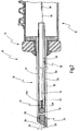
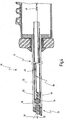
- FIGS. 1 to 4 an example of a provided with the general reference numeral 10 video endoscope is shown.
- a detail of the video endoscope 10 is in Figure 1A shown.
- the video endoscope 10 is used for example in the context of minimally invasive surgery to observe a body area inside the body.
- the video endoscope 10 has according to Figures 2 and 4 an elongate shaft 12, which in FIGS. 1 and 3 has been omitted for reasons of clarity.
- the shaft 12 has a longitudinal axis 14.
- the video endoscope 10 has a handpiece 16 to which the shaft 12 is connected.
- the stem 12 is constructed of a plurality of telescoped tubes, namely an outer tube 18, a central tube 20 and an inner tube 22 disposed therein.
- the structure of the stem 12 is made up of a plurality of tubes, such as tubes 18 20 and 22 is optional, and the shaft 12 may also be constructed from a single, two or more than three tubes.
- the inner tube 22 is rotatable relative to the other two tubes 18, 20 about the longitudinal axis 14.
- an objective 24 is arranged, which has two optical elements 26 and 28 by way of example.
- the objective 24 is an oblique-viewing objective, i. a viewing direction 30 of the objective 24 includes with the longitudinal axis 14 of the shaft 12 an angle 32 of ⁇ 0 °, in the embodiment shown, the angle 32 is 30 °.
- the lens is rotatably connected to the middle and the outer tube 18, 20 of the shaft 12.
- an electronic image sensor 34 is further arranged.
- the electronic image sensor 34 is fixedly connected to the distal end of the inner tube 22 in the embodiment shown.
- optical elements such as, for example, one or more filters may be arranged.
- the electronic image sensor 34 is designed, for example, in the form of a CCD or CMOS chip.
- the objective 24 images the observed body area onto the image recorder 34.
- the imager 34 converts the received optical signals into electrical signals.
- the electronic image sensor 34 is connected via an electrical connection 36 to an electrical connection 38, which is arranged here at the proximal end of the handpiece 16.
- the electrical connection 38 is designed as a socket.
- the electrical connection 36 is defined by at least one, in the example according to FIGS. 1 to 4 exactly accomplished a flexible elongated narrow circuit board 40 which is rotatable in itself about its longitudinal direction corresponding to the direction of the longitudinal axis 14.
- the circuit board 40 carries a plurality of interconnects, here by way of example four interconnects 40a, 40b on one of their surfaces, which are formed for example as thin copper lines.
- the printed circuit board 40 can carry further printed conductors.
- a distal circuit board part 44 connects at the distal end, which is rigid or at least stiffer than the flexible circuit board 40.
- the distal circuit board part 44 is used for contacting with the electronic image sensor 34.
- the width B of the circuit board 40 and the distal circuit board portion 44 is not greater than the corresponding width of Image pickup 34.
- the distal circuit board portion 44 is as shown FIG. 2 shows, thicker or stronger than the circuit board 40, which is designed to be as thin as possible to achieve high flexibility.
- the printed circuit board 40 is constructed in one layer from a planar carrier material, in particular polyimide, wherein the printed conductors 40a, 40b are vapor-deposited onto the carrier material, for example.
- the thickness of the circuit board 40 is preferably 0.02 to 0.3 mm.
- the distal printed circuit board part 44 carries electrical components, for example an amplifier circuit for (pre) amplification of the electrical video signals generated by the image sensor 34.
- the printed circuit board 40 extends through the shaft 12 into the handpiece 16, wherein a proximal end 46 of the printed circuit board 40 is followed by a proximal printed circuit board part 48.
- the proximal printed circuit board part 48 carries further electrical components 50 for controlling the image recorder 34.
- the proximal circuit board part 48 in turn is stiffer than the circuit board 40 and may in particular also be rigid, which simplifies the application of the electrical components 50.
- the proximal circuit board part 48 has the electrical connection 38 on the proximal side, which is designed here as a plug-in contact.
- the electrical connection 38 is connected to the proximal circuit board part 48 via a flexible web 52.
- the printed circuit board 40, the distal printed circuit board part 44 and the proximal printed circuit board part 48 together with the web 52 can be made in one piece from the same carrier material be manufactured, wherein the different degrees of flexibility between the circuit board 40, the distal circuit board part 44 and the proximal circuit board part 48 can be obtained by appropriate reinforcement of the support material in the region of the distal circuit board part 44 and the proximal circuit board part 48.
- the assembly of circuit board 40, distal circuit board member 44, and proximal circuit board member 48 may also be formed as a hybrid assembly, i. the distal and proximal circuit board parts 44 and 48 can be made of a carrier material, in particular a rigid carrier material, while the circuit board 40 can be made of a particularly flexible carrier material, in particular a polymeric plastic, in particular polyimide, wherein the individual plate parts then in a suitable manner , For example, by gluing, be connected together.
- the plastic can also be thermosetting.
- the printed circuit board 40 is preferably single-layered, and the printed conductors 40a to 40d are arranged in at most two planes of the printed circuit board, for example on the two opposite broad sides of the printed circuit board 40.
- the circuit board 40 may also be multi-layered, preferably constructed of two printed circuit board layers, which are firmly connected to each other. In terms of the highest possible flexibility of the printed circuit board 40, however, care must be taken that the thickness or thickness of the printed circuit board 40 is kept as low as possible.
- circuit board 40 may also be contemplated to provide the circuit board 40 with varying degrees of flexibility between its proximal end 46 and its distal end 42, with the flexibility then decreasing from the proximal end 46 to the distal end 42, e.g. in the region of the distal end 42, the printed circuit board 40 is stiffer than in the region of the proximal end 46.
- the distal printed circuit board part 44 is made up of two printed circuit board sections 44a and 44b.
- the electronic image sensor 34 is furthermore rotatable relative to the electrical connection 38 and to the objective 24 about the longitudinal axis 14 of the shaft 12.
- an actuator 54 is provided which acts on the inner tube 22 and this rotates about the longitudinal axis 14 of the shaft, whereby the Jardinaufillon 34, which is fixedly connected to the inner tube 22, is also rotated about the longitudinal axis 14.
- the imager 34 By rotating the imager 34, it is possible to keep the video image displayed on the monitor (not shown) always in a desired orientation with respect to the top, bottom, right and left, i. Align the video image in the desired manner.
- the image sensor 34 is in both directions of rotation (clockwise and counterclockwise) about the longitudinal axis 14 by preferably 180 ° rotated.
- a rotation of the image sensor 34 relative to the electrical connection 38 now causes a rotation of the circuit board 40 in itself, as in Figures 3 and 4 is shown.
- This rotation of the circuit board 40 is made possible by the fact that the circuit board 40 is designed to be rotatable in itself rotatable.
- FIG. 3 the state is shown in which the image sensor 34 opposite to the position in FIG. 1 is rotated by 180 ° about the longitudinal axis 14.
- the proximal printed circuit board part 48 has not twisted or essentially does not twist, while the distal printed circuit board part 44 has likewise rotated by 180 ° with the image recorder 34.
- the printed conductors 40a to 40d are not or hardly subjected to compression and expansion, as a result of which breakage of the printed conductors 40a to 40d is not to be feared even in the long-term use of the video endoscope 10.
- the video endoscope 10 has, between the outer tube 18 and the central tube 20, a channel 56 in which optical light for the illumination light is provided, wherein a connection 58 is provided at the proximal end for a light guide cable, not shown, and wherein the light at the distal end of the Shaft 12 exits at a light exit 60.
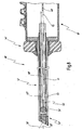
- FIGS. 5 to 8 is a first embodiment of a video endoscope 10 'is shown, in which with respect to the video endoscope 10 the same or similar parts with the same reference numerals, supplemented by a', are provided. Hereinafter, only the differences from the video endoscope 10 will be described.
- the electrical connection 36' between the image sensor 34 'and the electrical connection 38' is realized by two printed circuit boards 40 'and 41, which are arranged one above the other in the shaft 12' along the longitudinal axis 14 '.
- the distal circuit board part 44' connects again.
- the number of printed conductors for the electrical connection between the image sensor 34' and the terminal 38 ' can be increased without broadening the individual printed circuit boards 40' or 41 ', without the thickness and so that the rigidity of the circuit boards 40 'and 41 is increased.
- the circuit board 41 as well as the circuit board 40 ' is flexible and rotatable in itself about its longitudinal direction.
- circuit board 41 and the circuit board 40 'are as shown FIG. 6 emerges, spaced apart and thus mutually movable, whereby the overall flexibility of the two circuit boards 40 'and 41 is not or not substantially reduced compared to only one circuit board.
- the circuit boards 41 and 40' are interconnected via a flexible web 62, the web 62 also providing an electrical connection between the circuit boards 40 'and 41.
- the proximal circuit board part 48 ' must thus be electrically connected only to the circuit board 40'.
- circuit boards 40 'and 41 Prior to installation of the circuit boards 40 'and 41, these are preferably unfolded (see also Fig. 9 ), so that they lie in one plane.
- the printed circuit board layer 44'a is connected to the printed circuit board 41 and the printed circuit board layer 44'b of the distal printed circuit board part 44 'is connected to the printed circuit board 40'.
- these are then bent over the web 62 in a superimposed arrangement, as in FIG. 6 is shown, wherein the circuit board parts 44'a and 44'b are displaced against each other during insertion, so that they are easier to insert through the shaft (inner tube 22) can be inserted.
- FIG. 7 shows the video endoscope 10 'in a state in which the image sensor 34' by 180 ° from its position in FIG. 6 was twisted. How out FIGS. 7 and 8th As can be seen, the superimposed spaced arrangement of the circuit boards 40 'and 41 ensures that they can move relative to each other and each twist in itself.
- the electrical connection 36 ' by means of two printed circuit boards 40' and 41, these can be made of the same planar support material in one piece together with the printed circuit board parts 44 'and 48' and the web 62, or they can in hybrid construction of different support materials with respect on the circuit board parts 44 'and 48', the circuit boards 40 ', 41 may be formed.
- FIG. 9 shows a further modification of an electrical connection 36 ", which can be used in the video endoscope 10 or the video endoscope 10 'instead of the local electrical connections 36 and 36'.
- the electrical connection 36 here has two circuit boards 40" and 41 ", wherein the circuit board 40" at its distal end a printed circuit board part 44b “and the Circuit board 41 "at its distal end a printed circuit board part 44a” has.
- the arrangement corresponds to the embodiment in FIGS. 5 to 8 , wherein the circuit boards 40 "and 41” are still arranged side by side. At its proximal end, the printed circuit boards 40 "and 41” are connected to one another via the flexible web 62.
- the printed circuit board 41 "with its distal printed circuit board part 44a” is rotated 180 ° about a mirror axis 64 Drawing plane out on the circuit board 40 "folded, so that the resulting arrangement of the arrangement of the circuit boards 40 'and 41 according to FIGS. 5 to 8 equivalent.
- the electrical connection 36 "differs from the previous electrical connections 36 and 36 'in that the proximal circuit board part 48" is constructed in two parts, namely a first circuit board part 48a "and a second circuit board part 48b".
- the printed circuit board parts 48a “and 48b” are connected via a flexible web 49 which connects the printed circuit board parts 48a “and 48b” not only mechanically but also electrically.
- the electrical connection 38" is provided via the flexible web 52 ".
- the printed circuit board parts 48a" and 48b are folded over one axis 66, ie they are then located one above the other in the handpiece 16 or 16'. carry the electrical components 50a "and 50b".
Landscapes
- Health & Medical Sciences (AREA)
- Life Sciences & Earth Sciences (AREA)
- Surgery (AREA)
- Biomedical Technology (AREA)
- Medical Informatics (AREA)
- Optics & Photonics (AREA)
- Pathology (AREA)
- Radiology & Medical Imaging (AREA)
- Biophysics (AREA)
- Engineering & Computer Science (AREA)
- Physics & Mathematics (AREA)
- Heart & Thoracic Surgery (AREA)
- Nuclear Medicine, Radiotherapy & Molecular Imaging (AREA)
- Molecular Biology (AREA)
- Animal Behavior & Ethology (AREA)
- General Health & Medical Sciences (AREA)
- Public Health (AREA)
- Veterinary Medicine (AREA)
- Endoscopes (AREA)
- Instruments For Viewing The Inside Of Hollow Bodies (AREA)
Description
- Die Erfindung betrifft ein Videoendoskop, mit einem eine Längsachse aufweisenden langerstreckten Schaft und einem Handstück am proximalen Ende des Schafts, wobei an einem distalen Ende des Schafts ein Objektiv und proximalseitig des Objektivs ein elektronischer Bildaufnehmer angeordnet sind, wobei der Bildaufnehmer über eine sich längs des Schafts erstreckende elektrische Verbindung mit einem im Bereich des Handstücks angeordneten elektrischen Anschluss verbunden ist, und wobei der Bildaufnehmer und der Anschluss relativ zueinander um die Längsachse des Schafts verdrehbar sind.
- Ein derartiges Videoendoskop ist aus
DE 201 13 031 U1 bekannt. - Ein Videoendoskop ist ein Beobachtungsinstrument, das in der medizinischen Endoskopie verwendet wird. Durch die Verwendung eines Videoendoskops lassen sich im Rahmen der minimal-invasiven Chirurgie Körperregionen sowohl über natürliche Körperöffnungen als auch durch chirurgisch geschaffene künstliche Inzisionen erreichen. Bei Endoskopen allgemein unterscheidet man zwischen solchen, deren langerstreckter Schaft starr ist und solchen, deren langerstreckter Schaft flexibel ist. Die vorliegende Erfindung lässt sich sowohl bei starren Videoendoskopen als auch bei flexiblen Videoendoskopen einsetzen.
- Ein Videoendoskop ist eine spezielle Gattung von Endoskopen, bei denen die Bilderfassung und Bildweiterleitung anstatt über ein Linsensystem oder ein geordnetes Glasfaserbündel über einen elektronischen Bildaufnehmer und elektrische Leitungen realisiert ist.
- Aufgrund der heutigen Verfügbarkeit miniaturisierter elektronischer Bildaufnehmer, beispielsweise in CCD- oder CMOS-Technik, ist es möglich, den elektronischen Bildaufnehmer im distalen Ende des Schafts anzuordnen. Die Abbildung des beobachteten Objekts auf den Bildaufnehmer erfolgt dabei über ein distalseitig des elektronischen Bildaufnehmers angeordnetes Objektiv. Der elektronische Bildaufnehmer wandelt die empfangenen Photonen in elektrische Signale um, die über eine oder mehrere elektrische Leitungen, die sich vom Bildaufnehmer durch den Schaft hindurch bis zum Handstück des Videoendoskops erstrecken, nach proximal zu einem elektrischen Anschluss geleitet werden. Über den elektrischen Anschluss wird das Videoendoskop mittels eines Kabels mit einer Bildverarbeitungseinheit einschließlich Monitor verbunden, wobei auf dem Monitor das vom Bildaufnehmer erfasste Bild dargestellt wird. Die elektrische Verbindung, die sich durch den Schaft erstreckt, dient des Weiteren auch zur Ansteuerung und zur Spannungsversorgung des distalen Bildaufnehmers.
- Bei Videoendoskopen mit distalem elektronischem Bildaufnehmer ist die Orientierung des Arztes hinsichtlich des auf dem Monitor dargestellten Videobildes erschwert, wenn das Videoendoskop während der Beobachtung eines Körperareals um seine Längsachse gedreht wird. Wenn der Bildaufnehmer nämlich relativ zum Schaft drehfest ist, wird der Bildaufnehmer bei einer Drehung des Videoendoskops um seine Längsachse mitgedreht, was zwangsläufig zur Drehung des Bildes auf dem Monitor führt.
- Dieses Orientierungsproblem ist bei Videoendoskopen, deren Objektiv eine Geradeausblick- oder sogenannte 0°-Optik aufweist, durch Markierungen am Handgriff und im Monitorbild beherrschbar.
- Gravierender stellt sich dieses Problem jedoch bei Videoendoskopen dar, deren Objektiv eine Schrägblickoptik, beispielsweise eine 30°-, 45°- oder 90°-Optik aufweist. Bei einer Drehung eines Videoendoskops mit Schrägblickoptik um seine Längsachse ändert sich sowohl die Blickrichtung als auch die Orientierung des Gesichtsfeldes in Bezug auf oben, unten, rechts und links. Selbst mit Markierungen am Handgriff des Videoendoskops und im Monitorbild kann sich der Arzt nicht sicher räumlich im beobachteten Körperareal orientieren.
- Aus diesem Grund wurden Konzepte vorgeschlagen, mit denen eine Bildaufrichtung des Monitorbildes ermöglicht wird, so dass das Monitorbild stets eine definierte Orientierung in Bezug auf oben, unten, rechts und links besitzt.
- Eines dieser Konzepte besteht darin, den Monitor selbst zu drehen. Eine Monitordrehung ist zwar möglich, setzt aber aufwändige elektromechanische Aufbauten voraus, die im Operationsumfeld kritisch zu betrachten sind. Außerdem ist das übliche 4 : 3 bzw. 16:9 (HDTV)-Bildgrößenverhältnis für eine mechanische oder auch eine analog-elektronische Drehung über die Strahlablenkung, wie in
EP 7 12 289 A1 - Ein weiteres Konzept besteht darin, das auf dem Monitor dargestellte Bild mittels Bildverarbeitung zu drehen, wie beispielsweise in
US 5,313,306 beschrieben ist. Die Bildaufrichtung mittels digitaler Bildverarbeitung hat jedoch den Nachteil, dass kein vollformatiges 4: 3-Bild ohne Informationsverlust gedreht werden kann. Nur der mittige Inkreis im 3 : 3-Quadrat kann ohne Informationsverlust gedreht werden. Die mit Videoendoskopen arbeitenden Ärzte sind jedoch mit formatfüllenden Bildern, insbesondere in der Laparoskopie (Bauchraumchirurgie), mit der entsprechenden formatfüllenden Bildinformation vertraut und wollen auf diese nicht verzichten. - Das dritte Konzept zur Bildaufrichtung, von dem die vorliegende Erfindung ausgeht, besteht darin, den elektronischen Bildaufnehmer verdrehbar auszugestalten. Bei einer Drehung des Videoendoskops um seine Längsachse kann der Bildaufnehmer zur Beibehaltung einer bestimmten Orientierung durch eine Drehung relativ zum Schaft und zum schaftfesten Objektiv raumfest gehalten werden. Der Bildaufnehmer ist dadurch von dem Objektiv entkoppelt, was insbesondere bei einem Schrägblickobjektiv von Vorteil ist.
- Die Drehbarkeit des Bildaufnehmers relativ zum Schaft und damit auch zum proximalen elektrischen Anschluss stellt jedoch andere Herausforderungen an das Videoendoskop, insbesondere an die elektrische Verbindung zwischen dem Bildaufnehmer und dem proximalen elektrischen Anschluss.
- Bei einer Verdrehung des Bildaufnehmers relativ zum Schaft wird zwangsläufig die zumindest eine elektrische Verbindung zwischen dem Bildaufnehmer und dem elektrischen Anschluss verdreht, wenn der elektrische Anschluss am proximalen Ende des Handstücks drehfest bezüglich des Schafts ist.
- Bei dem o.g. Dokument
DE 201 13 031 U1 ist die elektrische Verbindung zwischen dem Bildaufnehmer und dem elektrischen Anschluss durch ein mehradriges Kabel realisiert. Da bei einem Videoendoskop mit Schrägblickoptik die Verdrehbarkeit des Bildaufnehmers im und entgegen dem Uhrzeigersinn um 180° möglich sein sollte, wird das mehradrige Kabel entsprechend stark auf Torsion beansprucht. Nach einer gewissen Anzahl an Lastwechseln und/oder nach mehreren Sterilisationen in einem Autoklaven neigt das Kabel zum Brechen, wodurch die Lebensdauer des Videoendoskops nachteilig verringert ist. - Zur Lösung dieses Problems wird in
DE 201 13 031 U1 vorgeschlagen, am proximalen Ende des Kabels einen Schleifkontakt vorzusehen, so dass das Kabel zusammen mit dem Bildaufnehmer torsionsfrei um seine Längsachse relativ zu dem elektrischen Anschluss gedreht werden kann. Diese Lösung hat jedoch den Nachteil, dass sie konstruktiv sehr aufwändig ist und darüber hinaus störanfällig ist. - Ein weiterer Nachteil der Ausgestaltung der elektrischen Verbindung mittels eines mehradrigen Kabels ist der hohe Aufwand bei der Herstellung des Videoendoskops, weil jede Ader einzeln mit dem Bildaufnehmer kontaktiert werden muss, was sich insbesondere bei miniaturisierter Ausgestaltung des Bildaufnehmers schwierig gestaltet.
- Aus
DE 10 2004 023 866 B3 ist ein Videoendoskop bekannt, das einen langerstreckten Schaft und ein darin distal angeordnetes Objektiv mit Videokamera aufweist. Die Videokamera weist Kamerakontakte auf, die über in dem Schaft verlaufende Leiter mit proximal in dem Schaft angeordneten Anschlusskontakten verbunden sind. Die Leiter sind als Leiterbahnen auf einer Leiterplatte ausgebildet. Die Leiterplatte ist flexibel ausgebildet, so dass sie in beliebiger Weise flexibel im Innenraum des Videoendoskopes verlegt und an den Enden mit den Kontaktierflächen in passende Lage zu den Kontakten gebracht werden kann. In einem weiteren in dem Dokument beschriebenen Ausführungsbeispiel ist die Leiterplatte aus starrem, gegebenenfalls auch dickerem Material ausgebildet. Die Leiterplatte kann dabei zur Verbesserung ihrer Drehsteifigkeit zu einem Dreiecksprofil geschlossen sein. - Aus dem Dokument
US 6,488,631 B2 ist ein Ultraschallendoskop offenbart, bei dem die elektrische Verbindung zwischen distal angeordneten Ultraschallwandlern und proximalem Anschluss im Bereich einer distalen Biegestelle des Endoskops durch eine Vielzahl von flexiblen Leiterplatten realisiert sind, die aus einem Rohr geschnitten sind. Der elektronische Bildaufnehmer dieses Endoskops ist dagegen mittels eines mehradrigen Kabels elektrisch mit dem proximalen Anschluss verbunden. - Der Erfindung liegt die Aufgabe zugrunde, ein Videoendoskop der eingangs genannten Art dahingehend weiterzubilden, dass die elektrische Verbindung zwischen dem Bildaufnehmer und dem elektrischen Anschluss mit geringem Aufwand und daher in kostengünstiger Weise ausgestaltet ist, die darüber hinaus ermüdungssicher ist und die Standzeit des Videoendoskops entsprechend erhöht ist.
- Erfindungsgemäß wird diese Aufgabe hinsichtlich des eingangs genannten Videoendoskops dadurch gelöst, dass die elektrische Verbindung zumindest eine in sich um ihre Längsrichtung verdrehbare flexible langerstreckte schmale Leiterplatte aufweist, die zumindest eine Leiterbahn aufweist, dass die elektrische Verbindung eine zweite in sich um ihre Längsrichtung verdrehbare flexible langerstreckte schmale Leiterplatte aufweist, die zumindest eine Leiterbahn aufweist, und dass die erste und die zweite Leiterplatte im Schaft übereinanderliegend und zueinander beweglich angeordnet sind, wobei die erste und die zweite Leiterplatte im Bereich ihres proximalen Endes über einen flexiblen Steg miteinander verbunden sind.
- Bei dem erfindungsgemäßen Videoendoskop ist die elektrische Verbindung zwischen dem Bildaufnehmer und dem proximalen elektrischen Anschluss anstatt durch ein mehradriges Kabel durch zumindest eine an einer flexiblen länglichen schmalen Leiterplatte ausgebildete Leiterbahn realisiert. Durch die Flexibilität der zumindest einen Leiterplatte ist gewährleistet, dass sich die Leiterplatte bei einer Verdrehung des Bildaufnehmers relativ zum elektrischen Anschluss in sich verdrehen bzw. verwinden kann, ohne - auch nach einer Vielzahl von wechselseitigen Verdrehungen - zu brechen, und ohne dass die zumindest eine Leiterbahn bricht. Die zumindest eine Leiterbahn kann als sehr dünne Metallisierung auf der im übrigen isolierend ausgebildeten Leiterplatte ausgebildet werden. Diese zumindest eine Leiterbahn oder auch mehrere Leiterbahnen können in oder nahe der bei einer Verwindung der Leiterplatte neutralen Zone ausgebildet werden, in der sich eine Verwindung der Leiterplatte nicht oder nahezu nicht in einer Verwindung der Leiterbahn äußert, wodurch die Leiterbahn im wesentlichen nicht gestaucht oder gedehnt wird.
- Die Verwendung zumindest einer Leiterplatte als elektrische Verbindung zwischen dem Bildaufnehmer und dem proximalen elektrischen Anschluss hat des Weiteren den Vorteil, dass auf einer Leiterplatte eine Mehrzahl von Leiterbahnen in Form von dünnen Metallisierungen, bspw. Kupfer, aufgebracht werden können, die für die Kontaktierung des Bildaufnehmers erforderlich sind, wie beispielsweise bei CCD-oder CMOS-Chips. Die Verwendung einer Mehrzahl von Kabeln oder eines mehradrigen Kabels entfällt somit vorteilhafterweise.
- Die Leiterplatte hat des Weiteren den Vorteil, bei gleichzeitig hoher Flexibilität eine hohe mechanische Stabilität zu besitzen, ebenso eine Temperaturstabilität, die den Bedingungen in einem Autoklaven gut Stand halten kann. Die Realisierung der elektrischen Verbindung des Bildaufnehmers über zumindest eine Leiterplatte ist im Vergleich zu Kabelsystemen hinsichtlich der Gestehungskosten außerdem kostengünstig, weil die längliche flexible Leiterplatte und auch die später noch zu beschreibenden ggf. vorhandenen Leiterplattenteile aus einem einzigen planaren Material hergestellt werden können.
- Auch der Aufwand beim Zusammenbauen des erfindungsgemäßen Videoendoskops ist durch die Verwendung zumindest einer Leiterplatte geringer, weil nicht mehrere Adern einzeln mit dem Bildaufnehmer kontaktiert werden müssen, sondern die Kontaktierung in einem einzigen Vorgang bspw. mit einem Balkenlötgerät erfolgen kann.
- Die Leiterplatte ist eine erste Leiterplatte, und die elektrische Verbindung weist eine zweite in sich um ihre Längsrichtung verdrehbare flexible langerstreckte schmale Leiterplatte auf, die zumindest eine Leiterbahn aufweist.
- Der Vorteil dieser Maßnahme besteht darin, dass zwei flexible längliche Leiterplatten zusammen mehr Leiterbahnen tragen können als eine Leiterplatte, und dabei beide Leiterplatten im Sinne einer höheren Flexibilität schmal ausgebildet werden können. Schmälere Leiterplatten haben wiederum den Vorteil, dass sie sich einfacher über die Länge im Rohr des Videoendoskops verdrehen lassen. Zwei Leiterplatten lassen sich aufgrund ihrer schmäleren Ausgestaltung auch einfacher in den Schaft des Videoendoskops integrieren, weil sie übereinanderliegend angeordnet werden können. Darüber hinaus ist zu berücksichtigen, dass elektrische Bildaufnehmer häufig zwei Reihen von seitlichen Anschlusspins aufweisen, so dass eine elektrische Verbindung über zwei Leiterplatten auch mechanisch besser an die Gegebenheiten des Bildaufnehmers angepasst ist.
- Die erste und die zweite Leiterplatte sind im Schaft übereinanderliegend und zueinander beweglich angeordnet.
- Diese Maßnahme hat den Vorteil, dass der Raum im Schaft des Videoendoskops durch die übereinanderliegende Anordnung, bei der die Leiterplatten demnach in zwei Ebenen angeordnet sind, besser genutzt werden kann. Durch die Beweglichkeit der beiden Leiterplatten zueinander wird die Flexibilität einer solchen Leiterplattenanordnung gegenüber einer einzelnen Leiterplatte nicht verringert.
- Die erste und die zweite Leiterplatte sind im Bereich ihres proximalen Endes über einen flexiblen Steg miteinander verbunden.
- Diese Maßnahme hat den Vorteil, dass die beiden Leiterplatten über den Steg, der dazu Leiterbahnen aufweist, miteinander elektrisch verbunden werden können, so dass nur eine der Leiterplatten mit dem Anschluss verbunden werden muss.
- In einer bevorzugten Ausgestaltung weist die zumindest eine Leiterplatte eine Mehrzahl an Leiterbahnen auf, die nebeneinander und höchstens in zwei Ebenen der Leiterplatte angeordnet sind.
- Diese Maßnahme hat den Vorteil, dass die zumindest eine Leiterplatte bei einer höchstens zweilagigen Ausgestaltung sehr dünn ausgebildet sein kann und die Leiterbahnen in der zentralen Zone angeordnet werden können, in der sie durch die Biegebeanspruchung der zumindest einen Leiterplatte weder wesentlich gedehnt noch wesentlich gestaucht werden. Da die Leiterbahnen linienförmig auf die Leiterplatte aufgebracht werden können, können auf einer solchen Leiterplatte eine Mehrzahl von Leiterbahnen nebeneinander angeordnet werden.
- In einer weiteren bevorzugten Ausgestaltung weist die zweite Leiterplatte eine Mehrzahl an Leiterbahnen auf, die nebeneinander und in höchstens zwei Ebenen der zweiten Leiterplatte angeordnet sind.
- Auch hier ist wiederum von Vorteil, dass einlagige bzw. höchstens zweilagige Leiterplatten eine optimale Flexibilität und dennoch ausreichende Stabilität besitzen.
- Der flexible Steg befindet sich vorzugsweise im Handstück des Videoendoskops und ist dort nicht in dem Maße einer Verdrehbeanspruchung unterworfen wie die Leiterplatten, die sich durch den Schaft hindurch erstrecken.
- In einer weiteren bevorzugten Ausgestaltung schließt sich an die zumindest eine Leiterplatte proximalseitig zumindest ein proximales, vorzugsweise starres, Leiterplattenteil an, das elektrische Bauteile trägt.
- Hierbei ist von Vorteil, dass weitere elektronische Bauelemente zur Bildaufnehmersteuerung, wie beispielsweise für die Identifikation des Bildaufnehmers, Längenlaufzeitkompensation des Videoendoskops, Verstärkungsanpassung, in die elektrische Verbindung integriert werden können. Eine starre Ausgestaltung des Leiterplattenteils hat den Vorteil, dass sie sich leichter mit den Bauteilen konfektionieren lässt.
- Dabei ist es weiterhin bevorzugt, wenn das proximale Platinenteil mit einem weiteren proximalen, vorzugsweise starren, Leiterplattenteil, das elektrische Bauteile trägt, über einen flexiblen Steg verbunden ist.
- Hierbei ist von Vorteil, dass die Anzahl an elektrischen Bauteilen, die auf der Leiterplatte proximal angeordnet werden können, erhöht werden kann, wobei die beiden proximalen Leiterplattenteile vorteilhafterweise über den flexiblen Steg im Handstück elektrisch miteinander verbunden sein können.
- In einer vorteilhaft platzsparenden Anordnung sind die beiden proximalen Leiterplattenteile im Handgriff übereinanderliegend angeordnet.
- In einer weiteren bevorzugten Ausgestaltung weist das zumindest eine proximale Leiterplattenteil den elektrischen Anschluss auf.
- Hierbei ist von Vorteil, dass der elektrische Anschluss bereits bei der Herstellung der gesamten elektrischen Verbindung aus Leiterplatte(n) und proximalen Plattenteil(en) in diese integriert werden kann, so dass die gesamte elektrische Verbindung als Baueinheit vorkonfektioniert in das Handstück und den Schaft eingebaut werden kann, was den Herstellungsaufwand des Videoendoskops reduziert.
- In einer weiteren bevorzugten Ausgestaltung weist die zumindest eine Leiterplatte an ihrem distalen Ende ein distales, vorzugsweise starres, Leiterplattenteil zur Kontaktierung mit dem Bildaufnehmer auf.
- Das distale Leiterplattenteil dient als Schnittstelle zum Bildaufnehmer, was den Vorteil einer einfach zu bewekstelligenden Kontaktierung hat.
- Das oder die starren Leiterplattenteile können, wie in einer weiteren bevorzugten Ausgestaltung vorgesehen ist, einstückig mit der flexiblen Leiterplatte aus einem planaren Trägermaterial gefertigt sein. Damit das oder die distalen Leiterplattenteile starr sind, können sie aus demselben Trägermaterial wie die Leiterplatte bzw. Leiterplatten selbst gefertigt sein, das dann im Bereich der distalen Leiterplattenteile verstärkt ist.
- Im Fall von zwei Leiterplatten mit jeweils einem distalen starren Leiterplattenteil können die beiden distalen Leiterplattenteile mechanisch und elektrisch verbunden sein, beispielsweise durch zwei durchgesteckte verlötete Drähte, um die mechanische Festigkeit im Bereich der Kontaktierung mit dem Bildaufnehmer zu erhöhen.
- In einer weiteren bevorzugten Ausgestaltung ist das distale Leiterplattenteil dicker und/oder breiter als die sich an das distale Leiterplattenteil anschließende Leiterplatte.
- Die Flexibilität der elektrischen Verbindung muss im Wesentlichen sich durch den Schaft erstreckenden Abschnitt, also im Bereich der flexiblen Leiterplatte gewährleistet sein. Das distale Leiterplattenteil ist dagegen vorzugsweise starr und kann daher auch dicker und/oder breiter als der sich an das distale Leiterplattenteil anschließende Teil der Leiterplatte ausgebildet sein, wodurch die zusätzliche Belegung des distalen Leiterplattenteils mit elektrischen Bauteilen vorteilhafterweise ermöglicht wird.
- Dabei ist es weiterhin bevorzugt, wenn die Breite des distalen Leiterplattenteils und/oder die Breite der zumindest einen Leiterplatte in ihrem sich durch den Schaft erstreckenden Abschnitt höchstens so groß ist wie die Breite des Bildaufnehmers.
- Hierbei ist von Vorteil, dass sich die zumindest eine Leiterplatte mit ihrem starren distalen Leiterplattenteil bzw. die zwei Leiterplatten mit ihrem jeweiligen distalen starren Leiterplattenteil zur Montage einfach von proximal nach distal durch den Schaft des Videoendoskops schieben lassen, wonach sie mit dem Bildaufnehmer kontaktiert werden können.
- In einer weiteren bevorzugten Ausgestaltung nimmt die Flexibilität der zumindest einen Leiterplatte von proximal nach distal bis zu dem distalen Leiterplattenteil kontinuierlich oder in Stufen ab.
- Bei dieser Ausgestaltung wird die zumindest eine Leiterplatte von distal nach proximal zunehmend flexibler, was den Vorteil hat, dass die Belastung bei der Verdrehung der zumindest einen Leiterplatte nicht an der Übergangsstelle zu dem starren distalen Leiterplattenteil wirkt, sondern sich über einen länglichen Bereich nach proximal verteilt.
- In einer weiteren bevorzugten Ausgestaltung ist die zumindest eine Leiterplatte einstückig aus einem planaren Trägermaterial gefertigt.
- Hierbei ist von Vorteil, dass die Leiterplatte kostengünstig hergestellt werden kann.
- Ebenso bevorzugt ist es im Zusammenhang mit einer der o.g. Ausgestaltungen, wonach zwei Leiterplatten vorgesehen sind, die über einen flexiblen Steg miteinander verbunden sind, wenn die erste und die zweite Leiterplatte und der sie verbindende Steg einstückig aus einem planaren Trägermaterial gefertigt sind.
- Ebenso ist es bevorzugt, im Zusammenhang mit einer der o.g. Ausgestaltungen, wonach die zumindest eine Leiterplatte ein proximales Leiterplattenteil aufweist, wenn die zumindest eine Leiterplatte und das zumindest eine proximale Leiterplattenteil einstückig aus einem planaren Trägermaterial gefertigt sind.
- Im Fall, dass wie in einer der o.a. Ausgestaltungen die zumindest eine Leiterplatte ein distales Leiterplattenteil aufweist, ist es bevorzugt, wenn die zumindest eine Leiterplatte und das zumindest eine distale Leiterplattenteil einstückig aus einem planaren Trägermaterial gefertigt sind.
- In einer weiteren bevorzugten Ausgestaltung ist das zuvor genannte Trägermaterial ein polymerer Kunststoff, insbesondere Polyimid.
- Ein polymerer Kunststoff, insbesondere Polyimid, hat den Vorteil einer hohen Flexibilität bzw. In-Sich-Verdrehbarkeit, ebenso wie guter Isolationseigenschaften und einer Gewichtsersparnis. Polyimid hat insbesondere den Vorteil einer sehr hohen thermischen Stabilität bei Temperaturen bis über 200°C, was für eine Sterilisierung des Videoendoskops in einem Autoklaven sehr vorteilhaft ist.
- Alternativ zur insgesamt einstückigen Bauweise der zumindest einen Leiterplatte und/oder der Leiterplattenteile ist es vorzugsweise vorgesehen, dass die zumindest eine Leiterplatte aus einer Mehrzahl von Leiterplattenabschnitten aufgebaut ist, die unterschiedliche Flexibilitäten aufweisen.
- Dazu kann die Leiterplatte abschnittsweise aus verschieden flexiblen Trägermaterialien aufgebaut sein. Ebenso können insbesondere das o.g. distale Leiterplattenteil und das proximale Leiterplattenteil als starre Platten ausgebildet sein, die stabiler als die Leiterplatte sind und sich somit besser für die Bestückung speziell für elektrische Bauteile eignen. Insbesondere lässt sich das zumindest eine proximale Leiterplattenteil bei einer starren Ausgestaltung insbesondere im Handstück leichter einbauen. Die Kontaktierung von elektrischen Bauteilen ebenso wie die Kontaktierung des Bildaufnehmers am distalen Leiterplattenteil sowie des elektrischen Anschlusses am proximalen Leiterplattenteil gestalten sich über starre Leiterplattenteile einfacher.
- In einer weiteren bevorzugten Ausgestaltung ist die zumindest eine Leiterplatte in ihrem flexiblen Bereich aus mehreren, vorzugsweise zwei Leiterplattenlagen aufgebaut.
- Während einlagige Leiterplatten den Vorteil einer sehr hohen Flexibilität besitzen, hat die Mehrlagigkeit der Leiterplatten, die auch abschnittsweise vorgesehen sein kann, den Vorteil, dass komplexe Schaltungsaufbauten auf engstem Raum realisiert werden können.
- Weitere Vorteile und Merkmale ergeben sich aus der nachfolgenden Beschreibung und der beigefügten Zeichnung.
- Es versteht sich, dass die vorstehend genannten und nachstehend noch zu erläuternden Merkmale nicht nur in der jeweils angegebenen Kombination, sondern auch in anderen Kombinationen oder in Alleinstellung verwendbar sind, ohne den Rahmen der vorliegenden Erfindung zu verlassen.
- Ausführungsbeispiele der Erfindung sind in der Zeichnung dargestellt und werden mit Bezug auf diese hiernach näher beschrieben. Es zeigen:
- Figur 1
- eine perspektivische Darstellung eines Videoendoskops gemäß einem Beispiel, wobei Teile des Videoendoskops weggelassen wurden, und wobei das Videoendoskop teilweise im Längsschnitt dargestellt ist;
- Figur 1A
- einen vergrößerten Ausschnitt eines Details des Videoendoskops in
Figur 1 ; - Figur 2
- einen Ausschnitt des Videoendoskops in
Figur 1 in vergrößertem Maßstab und im Längsschnitt; - Figur 3
- eine zu
Figur 1 vergleichbare Darstellung des Videoendoskops inFigur 1 in einem gegenüberFigur 1 veränderten Betriebszustand; - Figur 4
- eine zu
Figur 2 vergleichbare Darstellung des Videoendoskops in dem inFigur 3 gezeigten Betriebszustand; - Figur 5
- eine perspektivische Darstellung eines Videoendoskops gemäß einem Ausführungsbeispiel, wobei Teile des Videoendoskops weggelassen sind und das Videoendoskop teilweise im Längsschnitt dargestellt ist;
- Figur 6
- einen Ausschnitt des Videoendoskops in
Figur 5 im vergrößerten Maßstab und im Längsschnitt; - Figur 7
- das Videoendoskop in
Figur 5 in einer zuFigur 5 vergleichbaren Dar- stellung, jedoch in einem gegenüberFigur 5 geänderten Betriebszu- stand; - Figur 8
- das Videoendoskop in
Figur 5 in einer zuFigur 6 vergleichbaren Dar- stellung in dem Betriebszustand des Videoendoskops gemäßFigur 7 ; und - Figur 9
- ein weiteres Ausführungsbeispiel einer elektrischen Verbindung für das Videoendoskop in
Figur 1 oder inFigur 5 . - In
Figuren 1 bis 4 ist ein Beispiel eines mit dem allgemeinen Bezugszeichen 10 versehenen Videoendoskops dargestellt. Ein Detail des Videoendoskops 10 ist inFigur 1A dargestellt. - Das Videoendoskop 10 wird beispielsweise im Rahmen der minimal-invasiven Chirurgie zur Beobachtung eines Körperareals im Inneren des Körpers verwendet.
- Das Videoendoskop 10 weist gemäß
Figuren 2 und4 einen langerstreckten Schaft 12 auf, der inFiguren 1 und3 aus Gründen der Übersichtlichkeit weggelassen wurde. Der Schaft 12 weist eine Längsachse 14 auf. Am proximalen Ende des Schafts 12 weist das Videoendoskop 10 ein Handstück 16 auf, mit dem der Schaft 12 verbunden ist. - In dem gezeigten Ausführungsbeispiel ist der Schaft 12 aus mehreren ineinander geschobenen Rohren aufgebaut, und zwar einem äußeren Rohr 18, einem darin angeordneten mittleren Rohr 20 und einem inneren Rohr 22. Der Aufbau des Schafts 12 aus einer Mehrzahl von Rohren, wie hier den Rohren 18, 20 und 22 ist optional, und der Schaft 12 kann auch aus einem einzigen, aus zwei oder mehr als drei Rohren aufgebaut sein. Das innere Rohr 22 ist relativ zu den anderen Beiden Rohren 18, 20 um die Längsachse 14 verdrehbar.
- Am distalen Ende des Schafts 12 ist ein Objektiv 24 angeordnet, das beispielhaft zwei optische Elemente 26 und 28 aufweist. Das Objektiv 24 ist ein Schrägblickobjektiv, d.h. eine Blickrichtung 30 des Objektivs 24 schließt mit der Längsachse 14 des Schafts 12 einen Winkel 32 von ≠ 0° ein, im gezeigten Ausführungsbeispiel beträgt der Winkel 32 30°. Das Objektiv ist drehfest mit dem mittleren und dem äußeren Rohr 18, 20 des Schafts 12 verbunden.
- Proximalseitig des Objektivs 24, jedoch immer noch am distalen Ende des Schafts 12, ist weiterhin ein elektronischer Bildaufnehmer 34 angeordnet. Der elektronische Bildaufnehmer 34 ist in dem gezeigten Ausführungsbeispiel mit dem distalen Ende des inneren Rohrs 22 fest verbunden.
- Zwischen dem Objektiv 24 und dem Bildaufnehmer 34 können noch weitere optische Elemente, wie bspw. ein oder mehrere Filter, angeordnet sein.
- Der elektronische Bildaufnehmer 34 ist beispielsweise in Form eines CCD- oder CMOS-Chips ausgebildet.
- Das Objektiv 24 bildet das beobachtete Körperareal auf den Bildaufnehmer 34 ab. Der Bildaufnehmer 34 wandelt die empfangenen optischen Signale in elektrische Signale um.
- Der elektronische Bildaufnehmer 34 ist über eine elektrische Verbindung 36 mit einem elektrischen Anschluss 38, der hier am proximalen Ende des Handstücks 16 angeordnet ist, verbunden. Der elektrische Anschluss 38 ist als Steckbuchse ausgebildet.
- Die elektrische Verbindung 36 wird durch zumindest eine, in dem Beispiel gemäß
Figuren 1 bis 4 genau eine flexible längliche schmale Leiterplatte 40 bewerkstelligt, die in sich um ihre Längsrichtung, die der Richtung der Längsachse 14 entspricht, verdrehbar ist. - Wie in dem vergrößerten Ausschnitt in
Figur 1A dargestellt ist, trägt die Leiterplatte 40 eine Mehrzahl an Leiterbahnen, hier beispielhaft vier Leiterbahnen 40a, 40b auf einer ihrer Oberflächen, die beispielsweise als dünne Kupferlinien ausgebildet sind. Auf der gegenüberliegenden Seite kann die Leiterplatte 40 weitere Leiterbahnen tragen. - An einem distalen Ende 42 der Leiterplatte 40 schließt sich distalseitig ein distales Leiterplattenteil 44 an, das starr ist oder zumindest steifer als die flexible Leiterplatte 40. Das distale Leiterplattenteil 44 dient zur Kontaktierung mit dem elektronischen Bildaufnehmer 34. Wie aus
Figur 1 hervorgeht, ist die Breite B der Leiterplatte 40 sowie des distalen Leiterplattenteils 44 nicht größer als die entsprechende Breite des Bildaufnehmers 34. Das distale Leiterplattenteil 44 ist, wie ausFigur 2 hervorgeht, dicker bzw. stärker als die Leiterplatte 40, die zur Erzielung einer hohen Flexibilität möglichst dünn ausgebildet ist. - Die Leiterplatte 40 ist hier einlagig aus einem planaren Trägermaterial, insbesondere Polyimid, aufgebaut, wobei die Leiterbahnen 40a, bis 40b auf das Trägermaterial beispielsweise aufgedampft sind.
- Die Stärke oder Dicke der Leiterplatte 40 beträgt vorzugsweise 0,02 bis 0,3 mm.
- Das distale Leiterplattenteil 44 trägt elektrische Bauteile, beispielsweise eine Verstärkerschaltung zur (Vor-) Verstärkung der vom Bildaufnehmer 34 erzeugten elektrischen Videosignale.
- Die Leiterplatte 40 erstreckt sich durch den Schaft 12 hindurch bis in das Handstück 16, wobei sich an ein proximales Ende 46 der Leiterplatte 40 ein proximales Leiterplattenteil 48 anschließt.
- Das proximale Leiterplattenteil 48 trägt weitere elektrische Bauteile 50 zur Steuerung des Bildaufnehmers 34.
- Das proximale Leiterplattenteil 48 ist wiederum steifer als die Leiterplatte 40 und kann insbesondere auch starr sein, was die Aufbringung der elektrischen Bauteile 50 vereinfacht.
- Das proximale Leiterplattenteil 48 weist proximalseitig den elektrischen Anschluss 38 auf, der hier als Steckerkontaktierung ausgebildet ist. Der elektrische Anschluss 38 ist mit dem proximalen Leiterplattenteil 48 über einen flexiblen Steg 52 verbunden.
- Die Leiterplatte 40, das distale Leiterplattenteil 44 und das proximale Leiterplattenteil 48 nebst dem Steg 52 können insgesamt einstückig aus dem gleichen Trägermaterial gefertigt sein, wobei die unterschiedlichen Flexibilitätsgrade zwischen der Leiterplatte 40, dem distalen Leiterplattenteil 44 und dem proximalen Leiterplattenteil 48 durch entsprechende Verstärkung des Trägermaterials im Bereich des distalen Leiterplattenteils 44 und des proximalen Leiterplattenteils 48 erhalten werden können.
- Die Anordnung aus Leiterplatte 40, distalem Leiterplattenteil 44 und proximalem Leiterplattenteil 48 kann jedoch auch als Hybridanordnung ausgebildet sein, d.h. die distalen und proximalen Leiterplattenteile 44 und 48 können aus einem Trägermaterial, insbesondere einem steifen Trägermaterial gefertigt sein, während die Leiterplatte 40 aus einem besonders flexiblen Trägermaterial, insbesondere einem polymeren Kunststoff, insbesondere Polyimid, gefertigt sein kann, wobei die einzelnen Plattenteile dann auf geeignete Weise, beispielsweise durch Kleben, miteinander verbunden werden. Der Kunststoff kann auch duroplastisch sein.
- Die Leiterplatte 40 ist vorzugsweise einlagig, und die Leiterbahnen 40a bis 40d sind in höchstens zwei Ebenen der Leiterplatte angeordnet, beispielsweise auf den beiden gegenüberliegenden Breitseiten der Leiterplatte 40.
- Die Leiterplatte 40 kann jedoch auch mehrlagig, vorzugsweise aus zwei Leiterplattenlagen aufgebaut sein, die miteinander fest verbunden werden. Im Sinne einer möglichst hohen Flexibilität der Leiterplatte 40 ist jedoch darauf zu achten, dass die Dicke bzw. Stärke der Leiterplatte 40 möglichst gering gehalten wird.
- Es kann auch vorgesehen sein, die Leiterplatte 40 zwischen ihrem proximalen Ende 46 und ihrem distalen Ende 42 mit unterschiedlichen Flexibilitätsgraden auszustatten, wobei die Flexibilität dann vom proximalen Ende 46 zum distalen Ende 42 hin abnimmt, d.h. im Bereich des distalen Endes 42 ist die Leiterplatte 40 steifer als im Bereich des proximalen Endes 46.
- Wie aus
Figur 2 hervorgeht, ist das distale Leiterplattenteil 44 aus zwei Leiterplattenteillagen 44a und 44b aufgebaut. - Der elektronische Bildaufnehmer 34 ist des Weiteren relativ zu dem elektrischen Anschluss 38 und zu dem Objektiv 24 um die Längsachse 14 des Schafts 12 verdrehbar. Zur Verdrehbarkeit ist hier ein Stellglied 54 vorgesehen, das auf das innere Rohr 22 wirkt und dieses um die Längsachse 14 des Schafts dreht, wodurch der Bildaufnehmer 34, der mit dem inneren Rohr 22 fest verbunden ist, ebenfalls um die Längsachse 14 gedreht wird. Durch die Drehung des Bildaufnehmers 34 ist es möglich, das auf dem Monitor (nicht dargestellt) dargestellte Videobild stets in einer gewünschten Orientierung bezüglich oben, unten, rechts und links zu halten, d.h. das Videobild in gewünschter Weise auszurichten. Der Bildaufnehmer 34 ist dabei in beiden Drehrichtungen (Uhrzeigersinn und Gegenuhrzeigersinn) um die Längsachse 14 um vorzugsweise 180° verdrehbar.
- Eine Verdrehung des Bildaufnehmers 34 relativ zu dem elektrischen Anschluss 38 bedingt nun eine Verdrehung der Leiterplatte 40 in sich, wie in
Figuren 3 und4 dargestellt ist. - Diese Verdrehung der Leiterplatte 40 wird dadurch ermöglicht, dass die Leiterplatte 40 in sich verdrehbar flexibel ausgebildet ist. In
Figur 3 ist der Zustand dargestellt, in dem der Bildaufnehmer 34 gegenüber der Lage inFigur 1 um 180° um die Längsachse 14 verdreht ist. Das proximale Leiterplattenteil 48 hat sich dabei nicht oder im Wesentlichen nicht verdreht, während das distale Leiterplattenteil 44 sich mit dem Bildaufnehmer 34 ebenfalls um 180° verdreht hat. Die Leiterbahnen 40a bis 40d werden aufgrund der schmalen Breite B der Leiterplatte 40 nicht oder kaum auf Stauchung und Dehnung beansprucht, wodurch ein Bruch der Leiterbahnen 40a bis 40d auch im Langzeitgebrauch des Videoendoskops 10 nicht zu befürchten ist. - Das Videoendoskop 10 weist zwischen dem äußeren Rohr 18 und dem mittleren Rohr 20 einen Kanal 56 auf, in dem Lichtleitfasern für das Beleuchtungslicht verlaufen, wobei am proximalen Ende ein Anschluss 58 für ein nicht dargestelltes Lichtleitkabel vorgesehen ist, und wobei das Licht am distalen Ende des Schafts 12 an einem Lichtaustritt 60 austritt.
- In
Figuren 5 bis 8 ist ein erstes Ausführungsbeispiel eines Videoendoskops 10' dargestellt, bei dem in bezug auf das Videoendoskop 10 gleiche oder vergleichbare Teile mit den gleichen Bezugszeichen, ergänzt durch einen ', versehen sind. Nachfolgend werden nur die Unterschiede zu dem Videoendoskop 10 beschrieben. - Bei dem Videoendoskop 10' ist die elektrische Verbindung 36' zwischen dem Bildaufnehmer 34' und dem elektrischen Anschluss 38' durch zwei Leiterplatten 40' und 41 realisiert, die in dem Schaft 12' entlang der Längsachse 14' übereinander liegend angeordnet sind.
- An das distale Ende 42' bzw. 43' der Leiterplatten 40' und 41 schließt sich wieder das distale Leiterplattenteil 44' an.
- Durch die Verwendung von zwei Leiterplatten 40' und 41 lässt sich ohne Verbreiterung der einzelnen Leiterplatten 40' oder 41'die Anzahl an Leiterbahnen für die elektrische Verbindung zwischen dem Bildaufnehmer 34' und dem Anschluss 38' erhöhen, ohne dass die Dicke bzw. Stärke und damit die Steifigkeit der Leiterplatten 40' und 41 erhöht wird. Die Leiterplatte 41 ist ebenso wie die Leiterplatte 40' flexibel und in sich um ihre Längsrichtung verdrehbar.
- Die Leiterplatte 41 und die Leiterplatte 40' sind, wie aus
Figur 6 hervorgeht, voneinander beabstandet und somit zueinander beweglich, wodurch die Gesamtflexibilität der beiden Leiterplatten 40' und 41 gegenüber nur einer Leiterplatte nicht oder nicht wesentlich verringert ist. - An ihrem proximalen Ende 46' bzw. 47 sind die Leiterplatten 41 und 40' über einen flexiblen Steg 62 miteinander verbunden, wobei der Steg 62 außerdem eine elektrische Verbindung zwischen den Leiterplatten 40' und 41 herstellt. Das proximale Leiterplattenteil 48' muss somit nur mit der Leiterplatte 40' elektrisch verbunden sein.
- Vor dem Einbau der Leiterplatten 40' und 41 sind diese vorzugsweise auseinandergeklappt (vgl. auch
Fig. 9 ), so dass sie in einer Ebene liegen. Dabei ist die Leiterplattenteillage 44'a mit der Leiterplatte 41 und die Leiterplattenteillage 44'b des distalen Leiterplattenteils 44' mit der Leiterplatte 40' verbunden. Zum Einführen der Leiterplatten 40' und 41 werden diese dann über den Steg 62 in übereinander liegende Anordnung gebogen, wie inFigur 6 dargestellt ist, wobei die Leiterplattenteile 44'a und 44'b beim Einführen gegeneinander verschoben sind, damit sie leichter durch den Schaft (inneres Rohr 22) einschiebbar sind. -
Figur 7 zeigt das Videoendoskop 10' in einem Zustand, in dem der Bildaufnehmer 34' um 180° aus seiner Lage inFigur 6 verdreht wurde. Wie ausFiguren 7 und8 hervorgeht, gewährleistet die übereinander liegende beabstandete Anordnung der Leiterplatten 40' und 41, dass diese sich relativ zueinander bewegen und jeweils in sich verdrehen können. - Bei der Ausgestaltung der elektrischen Verbindung 36' mittels zwei Leiterplatten 40' und 41 können diese zusammen mit den Leiterplattenteilen 44' und 48' und dem Steg 62 aus demselben planaren Trägermaterial in einstückiger Weise gefertigt sein, oder sie können in Hybridbauweise aus unterschiedlichen Trägermaterialien in Bezug auf die Leiterplattenteile 44' und 48', die Leiterplatten 40', 41 ausgebildet sein.
-
Figur 9 zeigt eine weitere Abwandlung einer elektrischen Verbindung 36", die bei dem Videoendoskop 10 oder dem Videoendoskop 10' an Stelle der dortigen elektrischen Verbindungen 36 und 36' verwendet werden kann. - Auch hier wurden wiederum vergleichbare oder gleiche Teile wie in dem Ausführungsbeispiel gemäß
Figuren 1 bis 4 bzw. 5 bis 8 mit den gleichen Bezugszeichen, ergänzt durch ", versehen. - Die elektrische Verbindung 36" weist hier zwei Leiterplatten 40" und 41" auf, wobei die Leiterplatte 40" an ihrem distalen Ende ein distales Leiterplattenteil 44b" und die Leiterplatte 41" an ihrem distalen Ende ein distales Leiterplattenteil 44a" aufweist. Insoweit entspricht die Anordnung der Ausgestaltung in
Figuren 5 bis 8 , wobei die Leiterplatten 40" und 41" noch nebeneinander liegend angeordnet sind. An ihrem proximalen Ende sind die Leiterplatten 40" und 41" über den flexiblen Steg 62" miteinander verbunden. Im Einbauzustand in dem Videoendoskop 10 oder 10' wird die Leiterplatte 41" mit ihrem distalen Leiterplattenteil 44a" um eine Spiegelachse 64 um 180° aus der Zeichenebene heraus auf die Leiterplatte 40" umgeklappt, so dass die daraus resultierende Anordnung der Anordnung der Leiterplatten 40' und 41 gemäßFiguren 5 bis 8 entspricht. - Die elektrische Verbindung 36" unterscheidet sich von den vorherigen elektrischen Verbindungen 36 und 36' dadurch, dass das proximale Leiterplattenteil 48" zweiteilig aufgebaut ist, und zwar aus einem ersten Leiterplattenteil 48a" und einem zweiten Leiterplattenteil 48b". Die Leiterplattenteile 48a" und 48b" sind über einen flexiblen Steg 49 verbunden, der die Leiterplattenteil 48a" und 48b" nicht nur mechanisch, sondern auch elektrisch miteinander verbindet.
- An dem Leiterplattenteil 48a" ist über den flexiblen Steg 52" der elektrische Anschluss 38" vorgesehen.
- In der Einbaulage der elektrischen Verbindung 36" in dem Videoendoskop 10 oder dem Videoendoskop 10' sind die Leiterplattenteile 48a" und 48b" um eine Achse 66 aufeinandergeklappt, d.h. sie liegen dann im Handstück 16 oder 16' übereinander. Beide Leiterplattenteile 48a" und 48b" tragen dabei die elektrischen Bauteile 50a" und 50b".
Claims (21)
- Videoendoskop, mit einem eine Längsachse (14; 14') aufweisenden langerstreckten Schaft (12; 12') und einem Handstück (16; 16') am proximalen Ende des Schafts (12; 12'), wobei an einem distalen Ende des Schafts (12; 12') ein Objektiv (24; 24') und proximalseitig des Objektivs (24; 24') ein elektronischer Bildaufnehmer (34; 34') angeordnet sind, wobei der Bildaufnehmer (34; 34') über eine sich längs des Schafts (12; 12') erstreckende elektrische Verbindung (36; 36'; 36") mit einem am Handstück (16; 16') angeordneten elektrischen Anschluss (38; 38') verbunden ist, und wobei der Bildaufnehmer (34; 34') und der Anschluss (38; 38') relativ zueinander um die Längsachse (14; 14') des Schafts (12; 12') verdrehbar sind, dadurch gekennzeichnet, dass die elektrische Verbindung (36; 36'; 36") eine in sich um ihre Längsrichtung verdrehbare flexible langerstreckte schmale Leiterplatte (40; 40'; 40") aufweist, die zumindest eine Leiterbahn (40a-d) aufweist, dass die elektrische Verbindung (36'; 36") eine zweite in sich um ihre Längsrichtung verdrehbare flexible langerstreckte schmale Leiterplatte (41; 41") aufweist, die zumindest eine Leiterbahn (40a-d) aufweist, und dass die erste und die zweite Leiterplatte (40', 41; 40", 41") im Schaft (12') übereinanderliegend und zueinander beweglich angeordnet sind, wobei die erste und die zweite Leiterplatte (40', 41; 40", 41") im Bereich ihres proximalen Endes über einen flexiblen Steg (62, 62") miteinander verbunden sind.
- Videoendoskop nach Anspruch 1, dadurch gekennzeichnet, dass die zumindest eine Leiterplatte (40; 40'; 40") eine Mehrzahl an Leiterbahnen (40a-d) aufweist, die nebeneinander und höchstens in zwei Ebenen der Leiterplatte (40; 40'; 40") angeordnet sind.
- Videoendoskop nach Anspruch 1 oder 2, dadurch gekennzeichnet, dass die zweite Leiterplatte (41; 41") eine Mehrzahl an Leiterbahnen (40a-d) aufweist, die nebeneinander und in höchstens zwei Ebenen der zweiten Leiterplatte (41; 41") angeordnet sind.
- Videoendoskop nach einem der Ansprüche 1 bis 3, dadurch gekennzeichnet, dass sich an die zumindest eine Leiterplatte (40; 40'; 40") proximalseitig zumindest ein proximales, vorzugsweise starres, Leiterplattenteil (48; 48'; 48") anschließt, das elektrische Bauteile (50; 50'; 50") trägt.
- Videoendoskop nach Anspruch 4, dadurch gekennzeichnet, dass das proximale Leiterplattenteil (48a") mit einem weiteren proximalen, vorzugsweise starren, Leiterplattenteil (48b"), das elektrische Bauteile (50b") trägt, über einen flexiblen Steg (49) verbunden ist.
- Videoendoskop nach Anspruch 5, dadurch gekennzeichnet, dass die proximalen Leiterplattenteile (48a", 48b") im Handstück (16') übereinanderliegend angeordnet sind.
- Videoendoskop nach einem der Ansprüche 4 bis 6, dadurch gekennzeichnet, dass das zumindest eine proximale Leiterplattenteil (48; 48'; 48") den elektrischen Anschluss (38; 38'; 38") aufweist.
- Videoendoskop nach einem der Ansprüche 1 bis 7, dadurch gekennzeichnet, dass die zumindest eine Leiterplatte (40; 40'; 40") an ihrem distalen Ende ein distales, vorzugsweise starres, Leiterplattenteil (44; 44'; 44") zur Kontaktierung mit dem Bildaufnehmer (34; 34') aufweist.
- Videoendoskop nach Anspruch 8, dadurch gekennzeichnet, dass das distale Leiterplattenteil (44; 44'; 44") dicker und/oder breiter als die sich an das distale Leiterplattenteil (44; 44'; 44") anschließende Leiterplatte (40; 40'; 40") ist.
- Videoendoskop nach Anspruch 8 oder 9, dadurch gekennzeichnet, dass die Breite des distalen Leiterplattenteils (44; 44'; 44") höchstens so groß ist wie die Breite des Bildaufnehmers (34; 34').
- Videoendoskop nach einem der Ansprüche 1 bis 10, dadurch gekennzeichnet, dass die Flexibilität der zumindest einen Leiterplatte (40; 40'; 40") von proximal nach distal kontinuierlich oder in Stufen abnimmt.
- Videoendoskop nach einem der Ansprüche 1 bis 11, dadurch gekennzeichnet, dass die Breite der zumindest einen Leiterplatte (40; 40'; 40") höchstens so groß ist wie die Breite des Bildaufnehmers (34; 34').
- Videoendoskop nach einem der Ansprüche 1 bis 12, dadurch gekennzeichnet, dass die zumindest eine Leiterplatte (40; 40'; 40") einstückig aus einem planaren Trägermaterial gefertigt ist.
- Videoendoskop nach einem der Ansprüche 1 bis 3, dadurch gekennzeichnet, dass die erste und zweite Leiterplatte (40', 41; 40", 41") und der sie verbindende Steg (62; 62") einstückig aus einem planaren Trägermaterial gefertigt sind.
- Videoendoskop nach einem der Ansprüche 4 bis 7, dadurch gekennzeichnet, dass die zumindest eine Leiterplatte (40; 40'; 40") und das zumindest eine proximale Leiterplattenteil (48; 48'; 48") einstückig aus einem planaren Trägermaterial aufgebaut sind.
- Videoendoskop nach einem der Ansprüche 4 bis 7, dadurch gekennzeichnet, dass die zumindest eine flexible Leiterplatte (40; 40'; 40") und das zumindest eine proximale Leiterplattenteil (48; 48'; 48") verschiedenen Trägermaterialien oder aus dem gleichen Trägermaterial mit unterschiedlichen Flexibilitäten gefertigt sind.
- Videoendoskop nach einem der Ansprüche 8 bis 10, dadurch gekennzeichnet, dass die zumindest eine Leiterplatte (40; 40'; 40") und das zumindest eine distale Leiterplattenteil (44; 44'; 44") einstückig aus einem planaren Trägermaterial gefertigt sind.
- Videoendoskop nach einem der Ansprüche 8 bis 10, dadurch gekennzeichnet, dass die zumindest eine Leiterplatte (40; 40'; 40") und das zumindest eine distale Leiterplattenteil (44; 44'; 44") aus verschiedenen Trägermaterialien oder aus dem gleichen Trägermaterial mit unterschiedlichen Flexibilitäten gefertigt sind.
- Videoendoskop nach einem der Ansprüche 13 bis 18, dadurch gekennzeichnet, dass das Trägermaterial oder die Trägermaterialien ein polymerer Kunststoff, insbesondere Polyimid, ist.
- Videoendoskop nach einem der Ansprüche 1 bis 19, dadurch gekennzeichnet, dass die zumindest eine Leiterplatte (40; 40'; 40") aus einer Mehrzahl von Leiterplattenabschnitten aufgebaut ist, die unterschiedliche Flexibilitäten aufweisen.
- Videoendoskop nach einem der Ansprüche 1 bis 20, dadurch gekennzeichnet, dass die zumindest eine Leiterplatte (40; 40'; 40") in ihrem flexiblen Bereich aus mehreren, vorzugsweise zwei Leiterplattenlagen aufgebaut ist.
Applications Claiming Priority (1)
| Application Number | Priority Date | Filing Date | Title |
|---|---|---|---|
| DE102007009292A DE102007009292A1 (de) | 2007-02-16 | 2007-02-16 | Videoendoskop |
Publications (3)
| Publication Number | Publication Date |
|---|---|
| EP1958564A2 EP1958564A2 (de) | 2008-08-20 |
| EP1958564A3 EP1958564A3 (de) | 2008-10-08 |
| EP1958564B1 true EP1958564B1 (de) | 2011-06-08 |
Family
ID=39472635
Family Applications (1)
| Application Number | Title | Priority Date | Filing Date |
|---|---|---|---|
| EP08001973A Not-in-force EP1958564B1 (de) | 2007-02-16 | 2008-02-02 | Videoendoskop |
Country Status (4)
| Country | Link |
|---|---|
| US (1) | US8187171B2 (de) |
| EP (1) | EP1958564B1 (de) |
| AT (1) | ATE511783T1 (de) |
| DE (1) | DE102007009292A1 (de) |
Cited By (1)
| Publication number | Priority date | Publication date | Assignee | Title |
|---|---|---|---|---|
| DE102011109992A1 (de) * | 2011-08-11 | 2013-02-14 | Eppendorf Ag | Leiterplattenkabelvorrichtung für ein Laborprobengerät und Laborprobengerät |
Families Citing this family (72)
| Publication number | Priority date | Publication date | Assignee | Title |
|---|---|---|---|---|
| DE102007026234A1 (de) * | 2007-05-31 | 2008-12-04 | Karl Storz Gmbh & Co. Kg | Videoendoskop |
| KR100960262B1 (ko) * | 2008-08-14 | 2010-06-07 | 한전케이피에스 주식회사 | 촬상소자를 이용한 형상 연성회로 박막형 내시경장치 |
| US10165929B2 (en) | 2009-06-18 | 2019-01-01 | Endochoice, Inc. | Compact multi-viewing element endoscope system |
| US9713417B2 (en) | 2009-06-18 | 2017-07-25 | Endochoice, Inc. | Image capture assembly for use in a multi-viewing elements endoscope |
| US9872609B2 (en) | 2009-06-18 | 2018-01-23 | Endochoice Innovation Center Ltd. | Multi-camera endoscope |
| US9492063B2 (en) | 2009-06-18 | 2016-11-15 | Endochoice Innovation Center Ltd. | Multi-viewing element endoscope |
| US9101268B2 (en) | 2009-06-18 | 2015-08-11 | Endochoice Innovation Center Ltd. | Multi-camera endoscope |
| WO2012077116A1 (en) | 2010-12-09 | 2012-06-14 | Peermedical Ltd. | Flexible electronic circuit board for a multi-camera endoscope |
| US11278190B2 (en) | 2009-06-18 | 2022-03-22 | Endochoice, Inc. | Multi-viewing element endoscope |
| US12137873B2 (en) | 2009-06-18 | 2024-11-12 | Endochoice, Inc. | Compact multi-viewing element endoscope system |
| US11864734B2 (en) | 2009-06-18 | 2024-01-09 | Endochoice, Inc. | Multi-camera endoscope |
| US9101287B2 (en) | 2011-03-07 | 2015-08-11 | Endochoice Innovation Center Ltd. | Multi camera endoscope assembly having multiple working channels |
| US9402533B2 (en) | 2011-03-07 | 2016-08-02 | Endochoice Innovation Center Ltd. | Endoscope circuit board assembly |
| US11547275B2 (en) | 2009-06-18 | 2023-01-10 | Endochoice, Inc. | Compact multi-viewing element endoscope system |
| EP2442706B1 (de) | 2009-06-18 | 2014-11-12 | EndoChoice Innovation Center Ltd. | Mehrkamera-endoskop |
| US9901244B2 (en) | 2009-06-18 | 2018-02-27 | Endochoice, Inc. | Circuit board assembly of a multiple viewing elements endoscope |
| US9642513B2 (en) | 2009-06-18 | 2017-05-09 | Endochoice Inc. | Compact multi-viewing element endoscope system |
| US9706903B2 (en) | 2009-06-18 | 2017-07-18 | Endochoice, Inc. | Multiple viewing elements endoscope system with modular imaging units |
| US8926502B2 (en) | 2011-03-07 | 2015-01-06 | Endochoice, Inc. | Multi camera endoscope having a side service channel |
| US12220105B2 (en) | 2010-06-16 | 2025-02-11 | Endochoice, Inc. | Circuit board assembly of a multiple viewing elements endoscope |
| US9560953B2 (en) | 2010-09-20 | 2017-02-07 | Endochoice, Inc. | Operational interface in a multi-viewing element endoscope |
| EP4233680B1 (de) | 2010-09-20 | 2025-06-18 | EndoChoice, Inc. | Distaler endoskopabschnitt umfassend eine einheitliche flüssigkeitskanal-komponente |
| EP2635932B1 (de) | 2010-10-28 | 2019-06-05 | EndoChoice Innovation Center Ltd. | Optische systeme für multi-sensor-endoskope |
| US12204087B2 (en) | 2010-10-28 | 2025-01-21 | Endochoice, Inc. | Optical systems for multi-sensor endoscopes |
| EP3420886B8 (de) | 2010-12-09 | 2020-07-15 | EndoChoice, Inc. | Multikameraendoskop mit flexibler elektronischer leiterplatte |
| US11889986B2 (en) | 2010-12-09 | 2024-02-06 | Endochoice, Inc. | Flexible electronic circuit board for a multi-camera endoscope |
| DE102010063482A1 (de) * | 2010-12-20 | 2012-06-21 | Karl Storz Gmbh & Co. Kg | Elektrisches Kabel zur elektrischen Energie- und Datenübertragung |
| CN103491854B (zh) | 2011-02-07 | 2016-08-24 | 恩多卓斯创新中心有限公司 | 用于多摄影机内窥镜的多元件罩 |
| CA2798716A1 (en) | 2011-12-13 | 2013-06-13 | Endochoice Innovation Center Ltd. | Removable tip endoscope |
| CA2798729A1 (en) | 2011-12-13 | 2013-06-13 | Peermedical Ltd. | Rotatable connector for an endoscope |
| DE102011089157A1 (de) * | 2011-12-20 | 2013-06-20 | Olympus Winter & Ibe Gmbh | Videoendoskop mit seitlicher Blickrichtung und Verfahren zur Montage eines Videoendoskops |
| DE102011090132B4 (de) * | 2011-12-29 | 2017-09-14 | Olympus Winter & Ibe Gmbh | Videoendoskop und Videoendoskopsystem |
| DE102012005037A1 (de) | 2012-03-15 | 2013-09-19 | Olympus Winter & Ibe Gmbh | Endoskop mit einem langgestreckten Schaft und einer Schaltung |
| US9560954B2 (en) | 2012-07-24 | 2017-02-07 | Endochoice, Inc. | Connector for use with endoscope |
| DE102012017589A1 (de) | 2012-09-06 | 2014-03-06 | Olympus Winter & Ibe Gmbh | Leiterbahnträger |
| DE102012022475A1 (de) * | 2012-11-19 | 2014-05-22 | Olympus Winter & Ibe Gmbh | Videoendoskop und Verfahren zu seiner Herstellung |
| US10616491B2 (en) | 2013-02-01 | 2020-04-07 | Deka Products Limited Partnership | Endoscope with pannable camera and related method |
| EP2950701B1 (de) | 2013-02-01 | 2021-03-10 | DEKA Products Limited Partnership | Endoskop mit schwenkbarer kamera |
| CN105338883A (zh) * | 2013-03-15 | 2016-02-17 | 奥利弗医疗公司 | 用于刚性联接的图像传感器和内窥镜的机械图像旋转 |
| US9993142B2 (en) | 2013-03-28 | 2018-06-12 | Endochoice, Inc. | Fluid distribution device for a multiple viewing elements endoscope |
| US9986899B2 (en) | 2013-03-28 | 2018-06-05 | Endochoice, Inc. | Manifold for a multiple viewing elements endoscope |
| US10499794B2 (en) | 2013-05-09 | 2019-12-10 | Endochoice, Inc. | Operational interface in a multi-viewing element endoscope |
| USD745670S1 (en) * | 2014-05-16 | 2015-12-15 | Karl Storz Gmbh & Co. Kg | Video endoscope |
| DE102014212712A1 (de) * | 2014-07-01 | 2016-01-07 | Olympus Winter & Ibe Gmbh | Videoendoskop mit flexibler Leiterplatine |
| EP3103381A4 (de) * | 2014-10-20 | 2017-11-15 | Olympus Corporation | Festkörperbildgebungsvorrichtung und elektronisches endoskop mit einer derartigen festkörperbildgebungsvorrichtung |
| US10869592B2 (en) | 2015-02-23 | 2020-12-22 | Uroviu Corp. | Handheld surgical endoscope |
| WO2017119983A1 (en) * | 2016-01-05 | 2017-07-13 | UroSee Corporation | Handheld endoscope |
| US10874287B2 (en) | 2015-02-23 | 2020-12-29 | Uroviu Corp. | Handheld surgical endoscope |
| US10278563B2 (en) | 2015-02-23 | 2019-05-07 | Uroviu Corp. | Handheld surgical endoscope with detachable cannula |
| KR20250172897A (ko) * | 2015-09-01 | 2025-12-09 | 데카 프로덕츠 리미티드 파트너쉽 | 패닝가능한 카메라를 갖는 내시경 및 관련 방법 |
| DE102015118199A1 (de) | 2015-10-26 | 2017-04-27 | Karl Storz Gmbh & Co. Kg | Optisches medizinisches Instrument |
| US11832797B2 (en) | 2016-09-25 | 2023-12-05 | Micronvision Corp. | Endoscopic fluorescence imaging |
| US11684248B2 (en) | 2017-09-25 | 2023-06-27 | Micronvision Corp. | Endoscopy/stereo colposcopy medical instrument |
| JP6641330B2 (ja) | 2017-08-31 | 2020-02-05 | 株式会社フジクラ | 撮像モジュール付きカテーテル |
| JP6637933B2 (ja) * | 2017-08-31 | 2020-01-29 | 株式会社フジクラ | 撮像モジュール |
| JP6641329B2 (ja) * | 2017-08-31 | 2020-02-05 | 株式会社フジクラ | 撮像モジュール付きカテーテル |
| US12268358B2 (en) | 2019-12-05 | 2025-04-08 | Uroviu Corp. | Portable endoscope with side-mountable disposable portion |
| US11980342B2 (en) | 2020-11-12 | 2024-05-14 | Micronvision Corp. | Minimally invasive endoscope |
| US11771304B1 (en) | 2020-11-12 | 2023-10-03 | Micronvision Corp. | Minimally invasive endoscope |
| DE102017131171A1 (de) | 2017-12-22 | 2019-06-27 | Olympus Winter & Ibe Gmbh | Videoendoskop |
| EP3784109B1 (de) | 2018-04-26 | 2023-08-02 | DEKA Products Limited Partnership | Endoskop mit schwenkbarer kamera |
| US10433717B1 (en) * | 2018-06-28 | 2019-10-08 | Meditrina, Inc. | Endoscope having size-adjustable working channel |
| EP3829413B1 (de) | 2018-08-27 | 2025-04-30 | Meditrina, Inc. | Endoskop |
| DE102019100395B4 (de) * | 2019-01-09 | 2025-06-26 | Olympus Winter & Ibe Gmbh | Verbindungskörper eines Endoskops und Verfahren zum Montieren eines Endoskops |
| DE102019105564B4 (de) * | 2019-03-05 | 2023-02-02 | Olympus Winter & Ibe Gmbh | Endoskop |
| DE102019004433A1 (de) | 2019-06-22 | 2020-12-24 | Karl Storz Se & Co. Kg | Videoendoskop und Griff für ein Videoendoskop |
| EP4003138A4 (de) | 2019-07-25 | 2023-08-30 | Uroviu Corp. | Wegwerfbare endoskopiekanüle mit integriertem greifer |
| US11974722B2 (en) * | 2019-10-07 | 2024-05-07 | Boston Scientific Scimed, Inc. | Endoscopic device with interchangeable shaft |
| WO2022137233A1 (en) * | 2020-12-23 | 2022-06-30 | 270 Surgical Ltd. | Multi-camera endoscopes with maneuverable tips |
| EP4321858A1 (de) * | 2022-08-08 | 2024-02-14 | viZaar Industrial imaging AG | Sonde zur optischen inspektion, wartung und reparatur von maschinen, stromgeneratoren, turbinen und dampferzeugern |
| DE102023112524A1 (de) | 2023-05-10 | 2024-11-14 | Olympus Winter & Ibe Gmbh | Anordnung zum Schutz elektrischer Anschlüsse einer elektrischen Übertragungsleitung innerhalb eines Schafts eines Endoskops und ein Endoskop |
| DE102024102627A1 (de) * | 2024-01-30 | 2025-07-31 | Ambu A/S | Endoskop mit Lenkdrahtanordnung |
Family Cites Families (20)
| Publication number | Priority date | Publication date | Assignee | Title |
|---|---|---|---|---|
| US4858001A (en) * | 1987-10-08 | 1989-08-15 | High-Tech Medical Instrumentation, Inc. | Modular endoscopic apparatus with image rotation |
| US5313306A (en) | 1991-05-13 | 1994-05-17 | Telerobotics International, Inc. | Omniview motionless camera endoscopy system |
| NL9301210A (nl) | 1993-07-09 | 1995-02-01 | Robert Philippe Koninckx | Beeldweergavestelsel met beeldpositiecorrectie. |
| US5621830A (en) * | 1995-06-07 | 1997-04-15 | Smith & Nephew Dyonics Inc. | Rotatable fiber optic joint |
| WO1998035607A1 (en) * | 1997-02-13 | 1998-08-20 | Matsushita Electric Industrial Co., Ltd. | Endoscope, method of manufacturing the same, and inserting member |
| US6097423A (en) * | 1997-06-06 | 2000-08-01 | Karl Storz Imaging, Inc. | Image orientation for endoscopic video displays |
| US7037258B2 (en) * | 1999-09-24 | 2006-05-02 | Karl Storz Imaging, Inc. | Image orientation for endoscopic video displays |
| US6471637B1 (en) * | 1999-09-24 | 2002-10-29 | Karl Storz Imaging, Inc. | Image orientation for endoscopic video displays |
| DE19955229C1 (de) * | 1999-11-17 | 2001-08-09 | Winter & Ibe Olympus | Endoskop mit distaler Videokamera und Kameradreheinrichtung |
| US20050197533A1 (en) * | 2000-03-16 | 2005-09-08 | Medivision, Inc. | Endoscope and camera mount |
| US7175593B2 (en) * | 2000-08-30 | 2007-02-13 | Durell & Gitelis, Inc. | Variable view arthroscope with charge coupled device |
| JP3579646B2 (ja) | 2000-11-21 | 2004-10-20 | ペンタックス株式会社 | 超音波内視鏡 |
| DE10116056B4 (de) * | 2001-03-30 | 2005-09-08 | Karl Storz Gmbh & Co. Kg | Endoskopische Visualisierungsvorrichtung mit unterschiedlichen Bildsystemen |
| ATE546086T1 (de) * | 2001-06-18 | 2012-03-15 | Given Imaging Ltd | In-vivo-sensorvorrichtung mit einer leiterplatte aus starren und flexiblen abschnitten |
| DE20113031U1 (de) | 2001-08-04 | 2001-12-20 | Olympus Winter & Ibe Gmbh, 22045 Hamburg | Videoendoskop mit drehbarer Videokamera |
| JP4197975B2 (ja) * | 2003-02-27 | 2008-12-17 | オリンパス株式会社 | 医療機器用操作機構 |
| JP2005227382A (ja) * | 2004-02-10 | 2005-08-25 | Pentax Corp | デジタルカメラ |
| DE102004023866B3 (de) * | 2004-05-12 | 2006-02-23 | Olympus Winter & Ibe Gmbh | Videoendoskop mit Verbindungsleitern |
| DE102004044119B4 (de) * | 2004-09-11 | 2016-11-03 | Olympus Winter & Ibe Gmbh | Videoendoskop mit drehbarer Videokamera |
| JP2010506669A (ja) * | 2006-10-20 | 2010-03-04 | フェムスイート, エルエルシー | 光学外科用デバイスおよびその使用方法 |
-
2007
- 2007-02-16 DE DE102007009292A patent/DE102007009292A1/de not_active Withdrawn
-
2008
- 2008-02-02 EP EP08001973A patent/EP1958564B1/de not_active Not-in-force
- 2008-02-02 AT AT08001973T patent/ATE511783T1/de active
- 2008-02-14 US US12/031,345 patent/US8187171B2/en not_active Expired - Fee Related
Cited By (1)
| Publication number | Priority date | Publication date | Assignee | Title |
|---|---|---|---|---|
| DE102011109992A1 (de) * | 2011-08-11 | 2013-02-14 | Eppendorf Ag | Leiterplattenkabelvorrichtung für ein Laborprobengerät und Laborprobengerät |
Also Published As
| Publication number | Publication date |
|---|---|
| ATE511783T1 (de) | 2011-06-15 |
| US8187171B2 (en) | 2012-05-29 |
| EP1958564A2 (de) | 2008-08-20 |
| EP1958564A3 (de) | 2008-10-08 |
| US20080214892A1 (en) | 2008-09-04 |
| DE102007009292A1 (de) | 2008-08-21 |
Similar Documents
| Publication | Publication Date | Title |
|---|---|---|
| EP1958564B1 (de) | Videoendoskop | |
| EP1767139B1 (de) | Beleuchtungssystem für endoskopische Untersuchungen | |
| EP1182959B1 (de) | Bildaufnehmermodul sowie verfahren zum zusammenbauen eines derartigen bildaufnehmermoduls | |
| DE60006763T2 (de) | Endoskop mit einem Linsenantriebsmechanismus | |
| EP2438844B1 (de) | Gelenkabschnitt eines Schafts für ein endoskopisches Instrument | |
| WO2019211456A1 (de) | Endoskopdeflecting mit distalem abklappmechanismus | |
| DE102015210276A1 (de) | Endoskop und Verfahren zum Herstellen eines Endoskops | |
| WO2013120589A1 (de) | Elektrisches verbindungsstück für ein videoendoskop, videoendoskop und verfahren zum herstellen einer elektrischen verbindung in einem videoendoskop | |
| DE19535179A1 (de) | Abwinkelbares Rohr und Verfahren zu seiner Herstellung | |
| DE10157025B4 (de) | Ultraschallendoskop | |
| DE102020111889A1 (de) | Endoskop mit verbesserter Lenkdrahtanordnung | |
| DE102017102178B3 (de) | Endoskop und Fertigungsverfahren für ein Kameraboard mit Längsstiften mit drei Funktionen | |
| DE102004057481A1 (de) | Flexibler Schaft für ein Endoskop sowie derartiges Endoskop | |
| EP0842633A1 (de) | Voll autoklavierbares elektronisches Endoskop | |
| DE102020118047A1 (de) | Ablenksteuerungsmechanismus für ein lenkbares flexibles Endoskop, lenkbares flexibles Endoskop, Endoskopmontagesatz und Verfahren zur Montage eines flexiblen Endoskops | |
| EP2581031A1 (de) | Abwinkelungsvorrichtung | |
| DE102012108076A1 (de) | Schaft für ein flexibles Endoskop oder ein flexibles endoskopisches Instrument | |
| EP2417899B1 (de) | Schaftelement für ein endoskopisches Instrument | |
| DE102004023866B3 (de) | Videoendoskop mit Verbindungsleitern | |
| DE112017005361T5 (de) | Endoskop | |
| DE10157027B4 (de) | Ultraschallendoskop | |
| DE10157026B4 (de) | Ultraschallendoskop | |
| DE102011089132B4 (de) | Videoendoskop mit seitlicher Blickrichtung | |
| WO2016000974A1 (de) | Videoendoskop mit flexibler leiterplatine | |
| DE102019003842A1 (de) | Endoskop sowie Verfahren zur Herstellung eines Endoskops |
Legal Events
| Date | Code | Title | Description |
|---|---|---|---|
| PUAI | Public reference made under article 153(3) epc to a published international application that has entered the european phase |
Free format text: ORIGINAL CODE: 0009012 |
|
| AK | Designated contracting states |
Kind code of ref document: A2 Designated state(s): AT BE BG CH CY CZ DE DK EE ES FI FR GB GR HR HU IE IS IT LI LT LU LV MC MT NL NO PL PT RO SE SI SK TR |
|
| AX | Request for extension of the european patent |
Extension state: AL BA MK RS |
|
| PUAL | Search report despatched |
Free format text: ORIGINAL CODE: 0009013 |
|
| AK | Designated contracting states |
Kind code of ref document: A3 Designated state(s): AT BE BG CH CY CZ DE DK EE ES FI FR GB GR HR HU IE IS IT LI LT LU LV MC MT NL NO PL PT RO SE SI SK TR |
|
| AX | Request for extension of the european patent |
Extension state: AL BA MK RS |
|
| RAP1 | Party data changed (applicant data changed or rights of an application transferred) |
Owner name: KARL STORZ GMBH & CO. KG |
|
| 17P | Request for examination filed |
Effective date: 20090407 |
|
| AKX | Designation fees paid |
Designated state(s): AT BE BG CH CY CZ DE DK EE ES FI FR GB GR HR HU IE IS IT LI LT LU LV MC MT NL NO PL PT RO SE SI SK TR |
|
| 17Q | First examination report despatched |
Effective date: 20100217 |
|
| GRAP | Despatch of communication of intention to grant a patent |
Free format text: ORIGINAL CODE: EPIDOSNIGR1 |
|
| GRAC | Information related to communication of intention to grant a patent modified |
Free format text: ORIGINAL CODE: EPIDOSCIGR1 |
|
| GRAS | Grant fee paid |
Free format text: ORIGINAL CODE: EPIDOSNIGR3 |
|
| GRAA | (expected) grant |
Free format text: ORIGINAL CODE: 0009210 |
|
| AK | Designated contracting states |
Kind code of ref document: B1 Designated state(s): AT BE BG CH CY CZ DE DK EE ES FI FR GB GR HR HU IE IS IT LI LT LU LV MC MT NL NO PL PT RO SE SI SK TR |
|
| REG | Reference to a national code |
Ref country code: GB Ref legal event code: FG4D Free format text: NOT ENGLISH |
|
| REG | Reference to a national code |
Ref country code: CH Ref legal event code: EP |
|
| REG | Reference to a national code |
Ref country code: IE Ref legal event code: FG4D Free format text: LANGUAGE OF EP DOCUMENT: GERMAN |
|
| REG | Reference to a national code |
Ref country code: DE Ref legal event code: R096 Ref document number: 502008003755 Country of ref document: DE Effective date: 20110721 |
|
| REG | Reference to a national code |
Ref country code: NL Ref legal event code: VDEP Effective date: 20110608 |
|
| PG25 | Lapsed in a contracting state [announced via postgrant information from national office to epo] |
Ref country code: SE Free format text: LAPSE BECAUSE OF FAILURE TO SUBMIT A TRANSLATION OF THE DESCRIPTION OR TO PAY THE FEE WITHIN THE PRESCRIBED TIME-LIMIT Effective date: 20110608 Ref country code: NO Free format text: LAPSE BECAUSE OF FAILURE TO SUBMIT A TRANSLATION OF THE DESCRIPTION OR TO PAY THE FEE WITHIN THE PRESCRIBED TIME-LIMIT Effective date: 20110908 Ref country code: HR Free format text: LAPSE BECAUSE OF FAILURE TO SUBMIT A TRANSLATION OF THE DESCRIPTION OR TO PAY THE FEE WITHIN THE PRESCRIBED TIME-LIMIT Effective date: 20110608 Ref country code: LT Free format text: LAPSE BECAUSE OF FAILURE TO SUBMIT A TRANSLATION OF THE DESCRIPTION OR TO PAY THE FEE WITHIN THE PRESCRIBED TIME-LIMIT Effective date: 20110608 |
|
| PG25 | Lapsed in a contracting state [announced via postgrant information from national office to epo] |
Ref country code: CY Free format text: LAPSE BECAUSE OF FAILURE TO SUBMIT A TRANSLATION OF THE DESCRIPTION OR TO PAY THE FEE WITHIN THE PRESCRIBED TIME-LIMIT Effective date: 20110608 Ref country code: GR Free format text: LAPSE BECAUSE OF FAILURE TO SUBMIT A TRANSLATION OF THE DESCRIPTION OR TO PAY THE FEE WITHIN THE PRESCRIBED TIME-LIMIT Effective date: 20110909 Ref country code: FI Free format text: LAPSE BECAUSE OF FAILURE TO SUBMIT A TRANSLATION OF THE DESCRIPTION OR TO PAY THE FEE WITHIN THE PRESCRIBED TIME-LIMIT Effective date: 20110608 Ref country code: SI Free format text: LAPSE BECAUSE OF FAILURE TO SUBMIT A TRANSLATION OF THE DESCRIPTION OR TO PAY THE FEE WITHIN THE PRESCRIBED TIME-LIMIT Effective date: 20110608 Ref country code: LV Free format text: LAPSE BECAUSE OF FAILURE TO SUBMIT A TRANSLATION OF THE DESCRIPTION OR TO PAY THE FEE WITHIN THE PRESCRIBED TIME-LIMIT Effective date: 20110608 Ref country code: ES Free format text: LAPSE BECAUSE OF FAILURE TO SUBMIT A TRANSLATION OF THE DESCRIPTION OR TO PAY THE FEE WITHIN THE PRESCRIBED TIME-LIMIT Effective date: 20110919 |
|
| PG25 | Lapsed in a contracting state [announced via postgrant information from national office to epo] |
Ref country code: NL Free format text: LAPSE BECAUSE OF FAILURE TO SUBMIT A TRANSLATION OF THE DESCRIPTION OR TO PAY THE FEE WITHIN THE PRESCRIBED TIME-LIMIT Effective date: 20110608 |
|
| REG | Reference to a national code |
Ref country code: IE Ref legal event code: FD4D |
|
| PG25 | Lapsed in a contracting state [announced via postgrant information from national office to epo] |
Ref country code: EE Free format text: LAPSE BECAUSE OF FAILURE TO SUBMIT A TRANSLATION OF THE DESCRIPTION OR TO PAY THE FEE WITHIN THE PRESCRIBED TIME-LIMIT Effective date: 20110608 Ref country code: IE Free format text: LAPSE BECAUSE OF FAILURE TO SUBMIT A TRANSLATION OF THE DESCRIPTION OR TO PAY THE FEE WITHIN THE PRESCRIBED TIME-LIMIT Effective date: 20110608 Ref country code: PT Free format text: LAPSE BECAUSE OF FAILURE TO SUBMIT A TRANSLATION OF THE DESCRIPTION OR TO PAY THE FEE WITHIN THE PRESCRIBED TIME-LIMIT Effective date: 20111010 Ref country code: CZ Free format text: LAPSE BECAUSE OF FAILURE TO SUBMIT A TRANSLATION OF THE DESCRIPTION OR TO PAY THE FEE WITHIN THE PRESCRIBED TIME-LIMIT Effective date: 20110608 Ref country code: IS Free format text: LAPSE BECAUSE OF FAILURE TO SUBMIT A TRANSLATION OF THE DESCRIPTION OR TO PAY THE FEE WITHIN THE PRESCRIBED TIME-LIMIT Effective date: 20111008 |
|
| PG25 | Lapsed in a contracting state [announced via postgrant information from national office to epo] |
Ref country code: RO Free format text: LAPSE BECAUSE OF FAILURE TO SUBMIT A TRANSLATION OF THE DESCRIPTION OR TO PAY THE FEE WITHIN THE PRESCRIBED TIME-LIMIT Effective date: 20110608 Ref country code: SK Free format text: LAPSE BECAUSE OF FAILURE TO SUBMIT A TRANSLATION OF THE DESCRIPTION OR TO PAY THE FEE WITHIN THE PRESCRIBED TIME-LIMIT Effective date: 20110608 Ref country code: PL Free format text: LAPSE BECAUSE OF FAILURE TO SUBMIT A TRANSLATION OF THE DESCRIPTION OR TO PAY THE FEE WITHIN THE PRESCRIBED TIME-LIMIT Effective date: 20110608 |
|
| PLBE | No opposition filed within time limit |
Free format text: ORIGINAL CODE: 0009261 |
|
| STAA | Information on the status of an ep patent application or granted ep patent |
Free format text: STATUS: NO OPPOSITION FILED WITHIN TIME LIMIT |
|
| 26N | No opposition filed |
Effective date: 20120309 |
|
| PG25 | Lapsed in a contracting state [announced via postgrant information from national office to epo] |
Ref country code: DK Free format text: LAPSE BECAUSE OF FAILURE TO SUBMIT A TRANSLATION OF THE DESCRIPTION OR TO PAY THE FEE WITHIN THE PRESCRIBED TIME-LIMIT Effective date: 20110608 |
|
| REG | Reference to a national code |
Ref country code: DE Ref legal event code: R097 Ref document number: 502008003755 Country of ref document: DE Effective date: 20120309 |
|
| BERE | Be: lapsed |
Owner name: KARL STORZ G.M.B.H. & CO. KG Effective date: 20120228 |
|
| PG25 | Lapsed in a contracting state [announced via postgrant information from national office to epo] |
Ref country code: MC Free format text: LAPSE BECAUSE OF NON-PAYMENT OF DUE FEES Effective date: 20120229 |
|
| REG | Reference to a national code |
Ref country code: CH Ref legal event code: PL |
|
| PG25 | Lapsed in a contracting state [announced via postgrant information from national office to epo] |
Ref country code: CH Free format text: LAPSE BECAUSE OF NON-PAYMENT OF DUE FEES Effective date: 20120229 Ref country code: LI Free format text: LAPSE BECAUSE OF NON-PAYMENT OF DUE FEES Effective date: 20120229 |
|
| PG25 | Lapsed in a contracting state [announced via postgrant information from national office to epo] |
Ref country code: BE Free format text: LAPSE BECAUSE OF NON-PAYMENT OF DUE FEES Effective date: 20120228 |
|
| PG25 | Lapsed in a contracting state [announced via postgrant information from national office to epo] |
Ref country code: BG Free format text: LAPSE BECAUSE OF FAILURE TO SUBMIT A TRANSLATION OF THE DESCRIPTION OR TO PAY THE FEE WITHIN THE PRESCRIBED TIME-LIMIT Effective date: 20110908 |
|
| PG25 | Lapsed in a contracting state [announced via postgrant information from national office to epo] |
Ref country code: MT Free format text: LAPSE BECAUSE OF FAILURE TO SUBMIT A TRANSLATION OF THE DESCRIPTION OR TO PAY THE FEE WITHIN THE PRESCRIBED TIME-LIMIT Effective date: 20110608 |
|
| REG | Reference to a national code |
Ref country code: AT Ref legal event code: MM01 Ref document number: 511783 Country of ref document: AT Kind code of ref document: T Effective date: 20130202 |
|
| PG25 | Lapsed in a contracting state [announced via postgrant information from national office to epo] |
Ref country code: TR Free format text: LAPSE BECAUSE OF FAILURE TO SUBMIT A TRANSLATION OF THE DESCRIPTION OR TO PAY THE FEE WITHIN THE PRESCRIBED TIME-LIMIT Effective date: 20110608 |
|
| PG25 | Lapsed in a contracting state [announced via postgrant information from national office to epo] |
Ref country code: AT Free format text: LAPSE BECAUSE OF NON-PAYMENT OF DUE FEES Effective date: 20130202 Ref country code: LU Free format text: LAPSE BECAUSE OF NON-PAYMENT OF DUE FEES Effective date: 20120202 |
|
| PG25 | Lapsed in a contracting state [announced via postgrant information from national office to epo] |
Ref country code: HU Free format text: LAPSE BECAUSE OF FAILURE TO SUBMIT A TRANSLATION OF THE DESCRIPTION OR TO PAY THE FEE WITHIN THE PRESCRIBED TIME-LIMIT Effective date: 20080202 |
|
| REG | Reference to a national code |
Ref country code: FR Ref legal event code: PLFP Year of fee payment: 9 |
|
| REG | Reference to a national code |
Ref country code: FR Ref legal event code: PLFP Year of fee payment: 10 |
|
| REG | Reference to a national code |
Ref country code: FR Ref legal event code: PLFP Year of fee payment: 11 |
|
| REG | Reference to a national code |
Ref country code: DE Ref legal event code: R081 Ref document number: 502008003755 Country of ref document: DE Owner name: KARL STORZ SE & CO. KG INTELLECTUAL PROPERTY, DE Free format text: FORMER OWNER: KARL STORZ GMBH & CO. KG, 78532 TUTTLINGEN, DE Ref country code: DE Ref legal event code: R082 Ref document number: 502008003755 Country of ref document: DE Representative=s name: WITTE, WELLER & PARTNER PATENTANWAELTE MBB, DE Ref country code: DE Ref legal event code: R081 Ref document number: 502008003755 Country of ref document: DE Owner name: KARL STORZ SE & CO. KG, DE Free format text: FORMER OWNER: KARL STORZ GMBH & CO. KG, 78532 TUTTLINGEN, DE |
|
| PGFP | Annual fee paid to national office [announced via postgrant information from national office to epo] |
Ref country code: IT Payment date: 20180122 Year of fee payment: 11 |
|
| PG25 | Lapsed in a contracting state [announced via postgrant information from national office to epo] |
Ref country code: IT Free format text: LAPSE BECAUSE OF NON-PAYMENT OF DUE FEES Effective date: 20190202 |
|
| P01 | Opt-out of the competence of the unified patent court (upc) registered |
Effective date: 20230527 |
|
| PGFP | Annual fee paid to national office [announced via postgrant information from national office to epo] |
Ref country code: DE Payment date: 20240228 Year of fee payment: 17 Ref country code: GB Payment date: 20240220 Year of fee payment: 17 |
|
| PGFP | Annual fee paid to national office [announced via postgrant information from national office to epo] |
Ref country code: FR Payment date: 20240226 Year of fee payment: 17 |
|
| REG | Reference to a national code |
Ref country code: DE Ref legal event code: R119 Ref document number: 502008003755 Country of ref document: DE |
|
| GBPC | Gb: european patent ceased through non-payment of renewal fee |
Effective date: 20250202 |
|
| PG25 | Lapsed in a contracting state [announced via postgrant information from national office to epo] |
Ref country code: DE Free format text: LAPSE BECAUSE OF NON-PAYMENT OF DUE FEES Effective date: 20250902 |
|
| PG25 | Lapsed in a contracting state [announced via postgrant information from national office to epo] |
Ref country code: GB Free format text: LAPSE BECAUSE OF NON-PAYMENT OF DUE FEES Effective date: 20250202 |
|
| PG25 | Lapsed in a contracting state [announced via postgrant information from national office to epo] |
Ref country code: FR Free format text: LAPSE BECAUSE OF NON-PAYMENT OF DUE FEES Effective date: 20250228 |