EP1958746A1 - Schneidemittel für einen Schieferschneider - Google Patents
Schneidemittel für einen Schieferschneider Download PDFInfo
- Publication number
- EP1958746A1 EP1958746A1 EP20070121185 EP07121185A EP1958746A1 EP 1958746 A1 EP1958746 A1 EP 1958746A1 EP 20070121185 EP20070121185 EP 20070121185 EP 07121185 A EP07121185 A EP 07121185A EP 1958746 A1 EP1958746 A1 EP 1958746A1
- Authority
- EP
- European Patent Office
- Prior art keywords
- bracket
- blade
- frame
- dowel pin
- cutting means
- Prior art date
- Legal status (The legal status is an assumption and is not a legal conclusion. Google has not performed a legal analysis and makes no representation as to the accuracy of the status listed.)
- Withdrawn
Links
Images

Classifications
-
- B—PERFORMING OPERATIONS; TRANSPORTING
- B23—MACHINE TOOLS; METAL-WORKING NOT OTHERWISE PROVIDED FOR
- B23D—PLANING; SLOTTING; SHEARING; BROACHING; SAWING; FILING; SCRAPING; LIKE OPERATIONS FOR WORKING METAL BY REMOVING MATERIAL, NOT OTHERWISE PROVIDED FOR
- B23D45/00—Sawing machines or sawing devices with circular saw blades or with friction saw discs
- B23D45/04—Sawing machines or sawing devices with circular saw blades or with friction saw discs with a circular saw blade or the stock carried by a pivoted lever
- B23D45/042—Sawing machines or sawing devices with circular saw blades or with friction saw discs with a circular saw blade or the stock carried by a pivoted lever with the saw blade carried by a pivoted lever
- B23D45/044—Sawing machines or sawing devices with circular saw blades or with friction saw discs with a circular saw blade or the stock carried by a pivoted lever with the saw blade carried by a pivoted lever the saw blade being adjustable according to angle of cut
-
- B—PERFORMING OPERATIONS; TRANSPORTING
- B28—WORKING CEMENT, CLAY, OR STONE
- B28D—WORKING STONE OR STONE-LIKE MATERIALS
- B28D1/00—Working stone or stone-like materials, e.g. brick, concrete or glass, not provided for elsewhere; Machines, devices, tools therefor
- B28D1/02—Working stone or stone-like materials, e.g. brick, concrete or glass, not provided for elsewhere; Machines, devices, tools therefor by sawing
- B28D1/04—Working stone or stone-like materials, e.g. brick, concrete or glass, not provided for elsewhere; Machines, devices, tools therefor by sawing with circular or cylindrical saw-blades or saw-discs
- B28D1/047—Working stone or stone-like materials, e.g. brick, concrete or glass, not provided for elsewhere; Machines, devices, tools therefor by sawing with circular or cylindrical saw-blades or saw-discs with the work mounted on a carriage
-
- B—PERFORMING OPERATIONS; TRANSPORTING
- B28—WORKING CEMENT, CLAY, OR STONE
- B28D—WORKING STONE OR STONE-LIKE MATERIALS
- B28D1/00—Working stone or stone-like materials, e.g. brick, concrete or glass, not provided for elsewhere; Machines, devices, tools therefor
- B28D1/32—Methods and apparatus specially adapted for working materials which can easily be split, e.g. mica, slate, schist
- B28D1/327—Methods and apparatus specially adapted for working materials which can easily be split, e.g. mica, slate, schist for cutting or shearing easily splittable working materials
-
- Y—GENERAL TAGGING OF NEW TECHNOLOGICAL DEVELOPMENTS; GENERAL TAGGING OF CROSS-SECTIONAL TECHNOLOGIES SPANNING OVER SEVERAL SECTIONS OF THE IPC; TECHNICAL SUBJECTS COVERED BY FORMER USPC CROSS-REFERENCE ART COLLECTIONS [XRACs] AND DIGESTS
- Y10—TECHNICAL SUBJECTS COVERED BY FORMER USPC
- Y10T—TECHNICAL SUBJECTS COVERED BY FORMER US CLASSIFICATION
- Y10T83/00—Cutting
- Y10T83/768—Rotatable disc tool pair or tool and carrier
- Y10T83/7684—With means to support work relative to tool[s]
- Y10T83/7693—Tool moved relative to work-support during cutting
- Y10T83/7697—Tool angularly adjustable relative to work-support
-
- Y—GENERAL TAGGING OF NEW TECHNOLOGICAL DEVELOPMENTS; GENERAL TAGGING OF CROSS-SECTIONAL TECHNOLOGIES SPANNING OVER SEVERAL SECTIONS OF THE IPC; TECHNICAL SUBJECTS COVERED BY FORMER USPC CROSS-REFERENCE ART COLLECTIONS [XRACs] AND DIGESTS
- Y10—TECHNICAL SUBJECTS COVERED BY FORMER USPC
- Y10T—TECHNICAL SUBJECTS COVERED BY FORMER US CLASSIFICATION
- Y10T83/00—Cutting
- Y10T83/768—Rotatable disc tool pair or tool and carrier
- Y10T83/7872—Tool element mounted for adjustment
Definitions
- This invention generally relates to a cutting means for a slate cutter, particularly to a cutting means of which the cutting angle and cutting depth is adjustable.
- the purpose of the invention is to provide a cutting means for a slate cutter, which is able to cut at different angles and the height of the blade is adjustable, that ensures precise work, requires less energy and enhances work efficiency.
- the technical solution of the invention is a cutting means for a slate cutter, comprising: a base, a blade and a electric motor for driving the blade, a support arm is mounted on the base, the support arm comprises a bracket which is able to rotate perpendicularly to the surface of the blade, a frame is attached to the bracket, the electric motor is secured to the frame, one side of which is fixed to the bracket via a dowel pin, which is located eccentrically with respect to the axis of the blade.
- Said bracket has a L-shaped configuration, a fan shaped plate arranged perpendicularly to the surface of the blade with an arc-groove is provided on the support arm, the fan shaped plate is provided with a first bolt, which passes through the arc-groove and is connected to the vertical part of the bracket;
- the said frame has a U-shaped configuration, the front end of the bottom of the frame is connected to the horizontal part of the bracket via a first dowel pin and can rotate about the first dowel pin, a pressure plate is attached to the rear side of the bracket via a second dowel pin and can rotate about the second dowel pin, the first and second dowel pins are perpendicular to the surface of the blade, a elongated opening is defined along the longitudinal direction of the pressure plate, a second bolt passes through the elongated opening connected to the rear side of the frame.
- a cutting means for a slate cutter comprising:
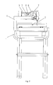
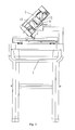
- the bracket 5 has a L-shaped configuration, a fan shaped plate 7 arranged perpendicularly to the surface of the blade 2 with an arc-groove 8 is provided on the support arm 4, the fan shaped plate is provided with a first bolt, the first bolt passes through the arc-groove connecting to the vertical part of the bracket, the cutting angle could be adjusted by change the position of the first bolt in the arc-groove.
- the said frame 6 has a U-shaped configuration, the front end of the bottom of the frame 6 is connected to the horizontal part of the bracket 5 via a first dowel pin 10 and can rotate about the first dowel pin 10, a pressure plate 12 is attached to the rear side of the bracket 5 via a second dowel pin 11 and can rotate about the second dowel pin 11, the first and second dowel pins (10,11) are perpendicular to the surface of the blade 2, a elongated opening 13 is defined along the longitudinal direction of the pressure plate 12, a second bolt 14 passes through the elongated opening 13 coupled to the rear side of the frame 6, the frame 6 could be lifted or brought down by changing the position of the second bolt 14 in the elongated opening 13.
Landscapes
- Engineering & Computer Science (AREA)
- Mechanical Engineering (AREA)
- Mining & Mineral Resources (AREA)
- Processing Of Stones Or Stones Resemblance Materials (AREA)
- Sawing (AREA)
Applications Claiming Priority (1)
| Application Number | Priority Date | Filing Date | Title |
|---|---|---|---|
| CNU2007200345981U CN201009372Y (zh) | 2007-02-15 | 2007-02-15 | 切割机的切割装置 |
Publications (1)
| Publication Number | Publication Date |
|---|---|
| EP1958746A1 true EP1958746A1 (de) | 2008-08-20 |
Family
ID=39044308
Family Applications (1)
| Application Number | Title | Priority Date | Filing Date |
|---|---|---|---|
| EP20070121185 Withdrawn EP1958746A1 (de) | 2007-02-15 | 2007-11-21 | Schneidemittel für einen Schieferschneider |
Country Status (3)
| Country | Link |
|---|---|
| US (1) | US20080196705A1 (de) |
| EP (1) | EP1958746A1 (de) |
| CN (1) | CN201009372Y (de) |
Families Citing this family (6)
| Publication number | Priority date | Publication date | Assignee | Title |
|---|---|---|---|---|
| CN103128862A (zh) * | 2011-12-03 | 2013-06-05 | 苏州豪特景精密机械有限公司 | 一种浮动切削装置 |
| CN102765135B (zh) * | 2012-07-23 | 2015-05-20 | 珠海华谷电机有限公司 | 一种石材、瓷砖类切割机 |
| CN108747773B (zh) * | 2018-06-08 | 2020-08-25 | 永康市金牛机械有限公司 | 防卡死自动定位检测砂轮锯装置 |
| CN110434396A (zh) * | 2019-06-11 | 2019-11-12 | 佛山市金立星机械设备有限公司 | 一种双头锯切割机 |
| CN111633434A (zh) * | 2020-06-05 | 2020-09-08 | 宁夏正德源科技发展股份有限公司 | 双面复合板折角系统 |
| CN116372257B (zh) * | 2023-05-25 | 2026-03-06 | 浙江世仓智能仓储设备有限公司 | 切断机构 |
Citations (4)
| Publication number | Priority date | Publication date | Assignee | Title |
|---|---|---|---|---|
| DE29822140U1 (de) * | 1998-12-11 | 1999-02-04 | Lissmac Maschinenbau und Diamantwerkzeuge GmbH, 88410 Bad Wurzach | Vorrichtung zum Sägen von Steinen |
| WO1999047324A1 (en) * | 1998-03-19 | 1999-09-23 | Darrell Greenland | Saw having movable table and saw blade |
| US6272961B1 (en) * | 2000-02-07 | 2001-08-14 | Wy Peron Lee | Cutting machine with built-in miter cutting feature |
| US6932075B1 (en) * | 2003-12-24 | 2005-08-23 | Wen-Hai Tsao | Blade angle adjustment device for a stone cutter |
Family Cites Families (11)
| Publication number | Priority date | Publication date | Assignee | Title |
|---|---|---|---|---|
| US2187299A (en) * | 1935-08-13 | 1940-01-16 | Burkhardt Otto Wilhelm | Dressing of individual blocks of stone |
| US2320743A (en) * | 1941-06-03 | 1943-06-01 | Nilsen Nicolai | Crosscut saw |
| US2546277A (en) * | 1947-01-29 | 1951-03-27 | Howard V Schwandt | Straight-line swinging saw |
| US2804065A (en) * | 1955-04-18 | 1957-08-27 | Frederick B Cordova Jr | Circular cutting of masonry slabs |
| US3302669A (en) * | 1964-06-29 | 1967-02-07 | Edler Adolph | Motor powered radial arm tool support |
| US4428159A (en) * | 1981-07-29 | 1984-01-31 | Sigetich John D | Portable, direct drive abrasive saw |
| US6276990B1 (en) * | 1997-08-05 | 2001-08-21 | Darrell Greenland | Tile saw having improved rollers |
| US6874399B2 (en) * | 2002-09-18 | 2005-04-05 | Wy Peron Lee | Cutting machine with built-in miter cutting feature |
| US6883511B1 (en) * | 2003-10-17 | 2005-04-26 | Wen-Hai Tsao | Portable stone cutter |
| US7044121B1 (en) * | 2003-12-22 | 2006-05-16 | Wen-Hai Tsao | Cutting mechanism minute adjustment device for a stone cutter |
| US7140361B1 (en) * | 2004-05-03 | 2006-11-28 | Teng Chao-Huan | Stone cutter having blade angle adjustment device |
-
2007
- 2007-02-15 CN CNU2007200345981U patent/CN201009372Y/zh not_active Expired - Fee Related
- 2007-11-14 US US11/984,134 patent/US20080196705A1/en not_active Abandoned
- 2007-11-21 EP EP20070121185 patent/EP1958746A1/de not_active Withdrawn
Patent Citations (4)
| Publication number | Priority date | Publication date | Assignee | Title |
|---|---|---|---|---|
| WO1999047324A1 (en) * | 1998-03-19 | 1999-09-23 | Darrell Greenland | Saw having movable table and saw blade |
| DE29822140U1 (de) * | 1998-12-11 | 1999-02-04 | Lissmac Maschinenbau und Diamantwerkzeuge GmbH, 88410 Bad Wurzach | Vorrichtung zum Sägen von Steinen |
| US6272961B1 (en) * | 2000-02-07 | 2001-08-14 | Wy Peron Lee | Cutting machine with built-in miter cutting feature |
| US6932075B1 (en) * | 2003-12-24 | 2005-08-23 | Wen-Hai Tsao | Blade angle adjustment device for a stone cutter |
Also Published As
| Publication number | Publication date |
|---|---|
| US20080196705A1 (en) | 2008-08-21 |
| CN201009372Y (zh) | 2008-01-23 |
Similar Documents
| Publication | Publication Date | Title |
|---|---|---|
| US20080196705A1 (en) | Cutting means for a slate cutter | |
| CN202462654U (zh) | 一种多功能瓷砖切割机 | |
| JP2002011702A5 (de) | ||
| CN206085222U (zh) | 一种自动化的木材切割装置 | |
| CN202241262U (zh) | 一种划线器 | |
| CN210115948U (zh) | 一种板材裁切台锯 | |
| KR102151865B1 (ko) | 판재절단용 전동식 원형톱장치 | |
| CN207757883U (zh) | 一种便携式高效瓷砖切割机 | |
| CN217752117U (zh) | 一种石板弧形切割器 | |
| CN211615941U (zh) | 带除尘功能的定位靠板装置 | |
| CN214868083U (zh) | 一种瑜伽垫裁剪修边装置 | |
| KR200387860Y1 (ko) | 판재재단기의 조기대장치 | |
| CN202780027U (zh) | 一种铝塑板开槽机 | |
| CN220261237U (zh) | 一种模切辅材生产的操作台 | |
| CN203712765U (zh) | 一种橡胶板切割装置 | |
| CN221793294U (zh) | 一种能够调整倾角的开槽锯电机 | |
| CN221756253U (zh) | 一种吉他琴颈板材的切割机 | |
| CN205552721U (zh) | 一种上装饰条加工机 | |
| CN220766834U (zh) | 一种控制面板定位切割装置 | |
| CN216442609U (zh) | 一种切缝装置 | |
| CN2472903Y (zh) | 墙地砖助切机 | |
| CN219032724U (zh) | 一种圆刀裁剪机 | |
| CN219075906U (zh) | 一种安全高效的推台锯 | |
| CN223589759U (zh) | 一种瓷砖倒角机 | |
| CN2565599Y (zh) | 滑轨式切割机 |
Legal Events
| Date | Code | Title | Description |
|---|---|---|---|
| PUAI | Public reference made under article 153(3) epc to a published international application that has entered the european phase |
Free format text: ORIGINAL CODE: 0009012 |
|
| AK | Designated contracting states |
Kind code of ref document: A1 Designated state(s): AT BE BG CH CY CZ DE DK EE ES FI FR GB GR HU IE IS IT LI LT LU LV MC MT NL PL PT RO SE SI SK TR |
|
| AX | Request for extension of the european patent |
Extension state: AL BA HR MK RS |
|
| 17P | Request for examination filed |
Effective date: 20090128 |
|
| AKX | Designation fees paid |
Designated state(s): DE GB PL |
|
| STAA | Information on the status of an ep patent application or granted ep patent |
Free format text: STATUS: THE APPLICATION HAS BEEN WITHDRAWN |
|
| 18W | Application withdrawn |
Effective date: 20091204 |