EP1958778A2 - Appareil d'enregistrement à jet d'encre - Google Patents
Appareil d'enregistrement à jet d'encre Download PDFInfo
- Publication number
- EP1958778A2 EP1958778A2 EP07253710A EP07253710A EP1958778A2 EP 1958778 A2 EP1958778 A2 EP 1958778A2 EP 07253710 A EP07253710 A EP 07253710A EP 07253710 A EP07253710 A EP 07253710A EP 1958778 A2 EP1958778 A2 EP 1958778A2
- Authority
- EP
- European Patent Office
- Prior art keywords
- ink
- light
- recording medium
- light source
- recording
- Prior art date
- Legal status (The legal status is an assumption and is not a legal conclusion. Google has not performed a legal analysis and makes no representation as to the accuracy of the status listed.)
- Granted
Links
Images


Classifications
-
- B—PERFORMING OPERATIONS; TRANSPORTING
- B41—PRINTING; LINING MACHINES; TYPEWRITERS; STAMPS
- B41J—TYPEWRITERS; SELECTIVE PRINTING MECHANISMS, i.e. MECHANISMS PRINTING OTHERWISE THAN FROM A FORME; CORRECTION OF TYPOGRAPHICAL ERRORS
- B41J2/00—Typewriters or selective printing mechanisms characterised by the printing or marking process for which they are designed
- B41J2/005—Typewriters or selective printing mechanisms characterised by the printing or marking process for which they are designed characterised by bringing liquid or particles selectively into contact with a printing material
- B41J2/01—Ink jet
- B41J2/135—Nozzles
- B41J2/145—Arrangement thereof
- B41J2/155—Arrangement thereof for line printing
-
- B—PERFORMING OPERATIONS; TRANSPORTING
- B41—PRINTING; LINING MACHINES; TYPEWRITERS; STAMPS
- B41J—TYPEWRITERS; SELECTIVE PRINTING MECHANISMS, i.e. MECHANISMS PRINTING OTHERWISE THAN FROM A FORME; CORRECTION OF TYPOGRAPHICAL ERRORS
- B41J11/00—Devices or arrangements of selective printing mechanisms, e.g. ink-jet printers or thermal printers, for supporting or handling copy material in sheet or web form
- B41J11/0015—Devices or arrangements of selective printing mechanisms, e.g. ink-jet printers or thermal printers, for supporting or handling copy material in sheet or web form for treating before, during or after printing or for uniform coating or laminating the copy material before or after printing
- B41J11/002—Curing or drying the ink on the copy materials, e.g. by heating or irradiating
- B41J11/0021—Curing or drying the ink on the copy materials, e.g. by heating or irradiating using irradiation
- B41J11/00214—Curing or drying the ink on the copy materials, e.g. by heating or irradiating using irradiation using UV radiation
Definitions
- the present invention relates to an ink jet recording apparatus, and more particularly to an ink jet recording apparatus for recording images in a recording medium having an ink absorbability such as paper or fabric.
- an image recording apparatus capable of recording images not only in a normal recording medium such as paper or fabric but also a recording medium of low ink absorbability such as a resin film or a metal
- an ink jet recording apparatus that jets an ink from a nozzle disposed in one end surface of a recording head so that the ink lands on the recording medium has been developed, and this technique is applied in various technical fields at present.
- a photocurable ink jet recording apparatus that applies light such as ultraviolet rays to the ink landed on the recording medium so as to harden and fix the ink has actively been developed as a recording apparatus which enables easy acquisition of high-definition images (e.g., Japanese Patent Application Laid-Open No. 2004-188864 and Japanese Patent Application Laid-Open No. Hei 6-200204 ).
- an ink jet recording apparatus in Japanese Patent Application Laid-Open No. 2004-188864 , the applicant of the present invention discloses a technique of an ink jet recording apparatus which includes a plurality of ultraviolet-ray sources different in a peak wavelength of emitted light as main sensitivity wavelengths of inks of various colors such as yellow (Y), magenta (M), cyan (C) and black (K) jetted from a recording head vary from ink to ink.
- an ink-jet apparatus where an ultraviolet-ray source having a shorter peak wavelength of emitted light is positioned closer to the recording head, so that ultraviolet rays of longer wavelengths is applied after application of an ultraviolet ray of a shorter wavelength to the ink landed on the recording medium.
- the ink jet recoding apparatus described in Japanese Patent Application Laid-Open No. 2004-188864 is useful especially when an image is recorded in a recording medium of low ink absorbability.
- the ink landed on a surface of the recording medium is irradiated with a short-wavelength ultraviolet ray to harden the surface, and then a long-wavelength ultraviolet ray is applied to harden the inside.
- blotting of the ink on the surface of the recording medium or color mixing such as mixing with an adjacent ink is prevented to enable acquisition of an extremely high-definition image.
- ink blending, storage management, jet control or the like is complex and burdensome, and besides resistance to abrasion of the ink hardened on the recording medium, i.e., abrasion resistance, may be reduced to cause image quality deterioration.
- An object of the present invention is to provide an ink jet recording apparatus capable of preventing ink blotting or print through and improving abrasion resistance when images are recorded in a recording medium having an ink absorbability.
- an ink jet recording apparatus for recording images in a recording medium having an ink absorbability, includes: a recording head including a nozzle for jetting a photocurable ink onto the recording medium; and a light irradiation device to apply light to the photocurable ink landed on the recording medium, wherein: the light irradiation device includes a first light source to emit light having a first emission spectrum, and a second light source to emit light having a second emission spectrum whose peak wavelength is shorter than a peak wavelength of the first emission spectrum, and the first and second light sources are arranged so that the first light source irradiates the photocurable ink landed on the recording medium and thereafter the second light source irradiates the photocurable ink.
- the lights having the first and second emission spectrums are ultraviolet rays.
- the light having the second emission spectrum is an ultraviolet ray having a peak wavelength at 280 nm or less belonging to a short wavelength ultraviolet region.
- each of the first and second light sources includes an LED.
- the ink jet recording apparatus includes a plurality of the recording heads, wherein the first light source is disposed at least between each two adjacent recording heads.
- the second light source is disposed in a rear end side of the recording head in a moving direction relative to the recording medium.
- an ink jet recording apparatus 1 of the embodiment includes a printer main body 3 supported in a support base 2.
- a platen 4 of a flat plate shape is arranged roughly horizontally to support a recording medium S from a nonrecording side.
- a convey roller and a driven roller are arranged to convey the recording medium S in the subscanning direction Y.
- the convey roller is driven to rotate intermittently by a predetermined amount by a convey motor (not shown).
- a convey motor not shown
- the recording medium S is intermittently conveyed in the subscanning direction Y while repeating movements and stops.
- a configuration can be employed in which an endless conveyor belt (not shown) is set between the convey roller and the driven roller, and the recording medium S is conveyed in a state of being mounted on the conveyor belt on an upper surface side of the platen 4.
- a recording medium having ink absorbability For the recording medium S, a recording medium having ink absorbability is used.
- recording media having an ink absorbability for example, various pieces of paper such as plain paper, recycled paper, glossy paper, various fabrics, and fabrics such as unwoven fabric not treated for blotting prevention are available.
- a recording medium such as a resin film normally having no ink absorbability can be used in the invention as long as ink absorbability is provided.
- a bar-shaped guide rail 5 is disposed above the platen 4, and a carriage 6 of a roughly casing shape is supported on the guide rail 5.
- This carriage 6 is reciprocated in a main scanning direction indicated by an arrow X (shown) along the guide rail 5 by a driving mechanism (not shown).
- an ink tank 7 is installed to store an ink of each color to be jetted from a recording head 10 described below.
- the ink is supplied from the ink tank 7 through a flexible tube 8 to the recording head 10.
- a maintenance unit 9 is installed to clean the recording head 10.
- a plurality of recording heads 10 are mounted on the carriage 6, and arranged in parallel in the main scanning direction X.
- Each recording head 10 scans above the recording medium S in association with the reciprocation of the carriage 6 along the guide rail 5 in the main scanning direction.
- a nozzle surface 10a is formed in a bottom surface of each recording head 10.
- the recording head 10 is arranged so that the nozzle surface 10a penetrates the bottom surface of the carriage 6 so as to face the recording medium S or the platen 4.
- a plurality of nozzles (not shown) are formed to jet the ink.
- a piezoelectric element (not shown) is arranged corresponding to each nozzle.
- the piezoelectric element is deformed by an electrostriction effect according to an applied driving voltage, and an inside of an ink room formed behind the nozzle is pressurized to jet the ink from each nozzle.
- the piezoelectric element of the embodiment can adjust a level of deformation according to an applied driving voltage. By changing the applied driving voltage, the amount of ink jetted from the nozzle, i.e., the amount of droplets per drop of ink, can be changed.
- a heater element can be used in place of the piezoelectric element.
- a driving voltage applied to the heater element by changing a driving voltage applied to the heater element, a growth rate of bubbles generated and grown by heating of the heater element can be changed to change the amount of ink jetted from the nozzle.
- the amount of ink jetted from the nozzle can be changed by changing the number of ink drops jetted from the nozzle.
- each color ink is supplied to a corresponding recording head 10 from each ink tank 7 which stores each of color inks of yellow (Y), magenta (M), cyan (C), and black (K). Inks of the same color are jetted from the nozzles belonging to one recording head 10.
- the ink used according to the embodiment is a photocurable ink hardened when irradiated with light.
- an ultraviolet curable ink hardened when irradiated with ultraviolet rays is preferably used.
- the photocurable ink includes main components of at least a polymerizable compound containing a well-known polymerizable compound, a photoinitiator, and a coloring material.
- a coloring material pigments are preferably used from the standpoint of weather resistance or the like. No photoinitiator may be used depending on an ink composition.
- a radical polymerization ink containing a radical polymerization compound as a polymerizable compound or a cationic polymerization ink containing a cationic polymerization compound is preferably used, or a hybrid type ink combining the radical polymerization ink and the cationic polymerization ink can be used.
- the cationic polymerization ink has excellent functionality and versatility because of a limited inhibition effect of polymerization reaction by oxygen or no inhibition effect.
- the cationic polymerization ink of the embodiment is a mixture containing at least a cationic polymerization compound such as an oxetane compound, an epoxy compound or a vinyl ether compound, a photo cation initiator, and pigments, and having the nature of being hardened when irradiated with ultraviolet rays.
- a cationic polymerization compound such as an oxetane compound, an epoxy compound or a vinyl ether compound, a photo cation initiator, and pigments
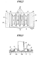
- First light irradiation devices 11 are disposed among the plurality of recording heads 10 arranged in parallel on the carriage 6 in the main scanning direction X. According to the embodiment, the first light irradiation devices 11 are disposed not only among the recording heads 10 but also each outside of the recording heads 10 of both ends of the main scanning direction X.
- each first light irradiation device 11 includes a first light source 12 to emit light having a first emission spectrum, and the first light source 12 includes an LED.
- the LED is advantageous in that lighting is instantaneous and a life is long.
- another component such as a high pressure mercury lamp, a metal halide lamp, a black light, a hot cathode tube, or a cold cathode tube which can emit ultraviolet rays can be used.
- a light source to emit a visible light or infrared rays can be used as long as it can harden or thicken the ink landed on the recording medium therein.
- a plurality of circular LEDs are arrayed in line in a bottom surface of the first light irradiation device 11. As in the case of the nozzle surface of the recording head 10 described above, the LED is arranged to penetrate the bottom portion of the carriage 6, thereby facing the recording medium S. Light emitted from the LED is directly applied to the recording medium S.
- a light trap 13 is disposed between each recording head 10 and each first light irradiation device 11.
- the light trap 13 is provided to prevent light emitted from the first light source 12 from being reflected on the recording medium S to reach the nozzle surface 10a of the recording head 10.
- FIG. 3 shows a light trap 13 having U-shaped cross-section and opened toward the recording medium S.
- the light trap 13 is properly formed into a shape to effectively trap a reflected light.
- an inner surface 13a is properly processed such as coating of a light absorber for absorbing light on the inner surface 13a of the light trap 13.
- a second light irradiation device 14 is disposed in a rear end side of the recording head 10 in a moving direction of the recording head 10 relative to the recording medium S, i.e., a rear end side of the main scanning direction of the recording head 10 moved above the recording medium S in the main scanning direction X.
- the recording head 10 jets inks in both cases of going and returning operations of the reciprocation in the main scanning direction X.
- rear end sides of the main scanning direction X are both end sides of the recording head 10 in the main scanning direction X
- second light irradiation devices 14 are disposed each outside of the first light irradiation device 11 disposed outside both ends of the recording head 10 in the main scanning direction X.
- Each second light irradiation device 14 includes a second light source 15 to emit light having a second emission spectrum.
- the second light source 15 includes a low pressure mercury lamp.
- the low pressure mercury lamp has a peak wavelength of its emission spectrum in a wavelength area of 280 nm or less which is a so-called short wavelength ultraviolet region (UV-C area).
- the second light source 15 is preferably configured to emit an ultraviolet ray having a peak wavelength at 280 nm or less.
- an LED capable of emitting such ultraviolet rays can be used.
- each second light irradiation device 11 a reflection plate 16 having cross-section of a roughly semi-spindle shape in which the end of the recording medium S side is opened is arranged to surround the second light source 15. Light emitted from the second light source 15 is reflected on the reflection plate 16 to be applied to the recording medium S.
- arrangement is similar to that of the first light irradiation device 11 and the first light source 12.
- Lights emitted from light sources normally have fixed wavelength distributions.
- a peak wavelength of an emission spectrum of the second light source 15 is set to be shorter than that of an emission spectrum of the first light source 12.
- the single wavelength is equivalent to the peak wavelength.
- a difference in peak wavelength between the two light sources 12 and 15 is preferably 50 nm or more, more preferably 100 nm or more.
- first and second light sources 12 and 15 both emit ultraviolet rays, easily handled well-known light sources can be used, and preferable as determination and adjustment of a corresponding composition of ink are easy.
- a light source to emit a visible light or infrared rays can be used for the first light source 12 is required to emit light of a longer wavelength.
- the second light source 14 required to emit light of a shorter wavelength is a light source having a peak wavelength of an emission spectrum in a wavelength area of 280 nm or less which is a so-called short wavelength ultraviolet region as in the case of the embodiment, it is preferable because at least a surface of the ink on the recording medium S is surely hardened and ink abrasion resistance is increased.
- the carriage 6 reciprocates above the recording medium S stopped on the platen 4 in the main scanning direction X during image recording.
- the recording head 10 scans on the recording medium S in association with the reciprocation of the carriage 6, and an ink is properly jetted from the nozzle to record an image of a predetermined width in the recording medium S.
- the convey roller Upon an end of one-direction scanning and recording of the recording head in the main scanning direction X, the convey roller rotates to convey the recording medium S by a predetermined amount on the platen 4 in the subscanning direction Y and then to stop the same.
- the convey roller conveys the recording medium S again by a predetermined amount in the subscanning direction Y to stop. Accordingly, the scanning of the recording head 10 in the main scanning direction X and the intermittent conveying of the recording medium S by the convey roller in the subscanning direction Y are associated with each other to record a predetermined image in the recording medium S.
- the scanning of the recording head 10 in the main scanning direction X i.e., the movement of the carriage 6 in the main scanning direction X
- the movement of the carriage 6 in the main scanning direction X is accompanied by the movement of the first light irradiation device 11 above the ink landed on the recording medium S
- the ink is irradiated with light from the first light source 12 of the first light irradiation device 11.
- the light emitted from the first light source 12 is light having a peak wavelength on a long wavelength side and containing many long-wavelength components. Accordingly, the long-wavelength components of the light reach the inside of the ink to large extent without being affected so much by scattering caused by pigments of the ink, thereby hardening or thickening the ink from the inside.
- the ink started to permeate the recording medium S stops spreading in a surface or thickness direction of the recording medium S.
- the light emitted from the second light source 15 is light having a peak wavelength on a short wavelength side and containing many short wavelength components. Accordingly, the short wavelength components of the light are emitted in large quantity to harden the surface of the ink. Long wavelength components contained in the light reach the inside of the ink to harden the ink from the inside.
- the ink jet recording apparatus 1 of the embodiment first, the light having a peak wavelength on the long wavelength side is applied to the ink landed on the recording medium S having an ink absorbability to surely reach the inside of the ink, and the ink is hardened or thickened from the inside so that the ink started to permeate the recording medium S can stop spreading in the surface or thickness direction of the recording medium S.
- blocking of spreading of the ink in the surface direction of the recording medium S enables sure prevention of blotting of the ink, and effective prevention of color mixing with an adjacent ink.
- blocking of spreading of the ink in the thickness direction of the recording medium S enables sure prevention of print through of the ink.
- the ink is hardened more, and its surface is surely hardened.
- resistance to ink abrasion i.e., ink abrasion resistance
- ink abrasion resistance can be increased, and a high-quality image having strong resistance to abrasion can be obtained.
- the ink landed on the recording medium S can surely receive the light from the first light source 12 before the light from the second light source 15. Moreover, with this configuration, a distance between the nozzle of the recording head 10 and the first light source 12 can be designed to be constant among the recording heads 10. Thus, levels of ink spreading on the recording medium S can be set equal among all the recording heads 10, and a higher quality image can be obtained.
- the ink landed on the recording medium S is fist blocked from spreading by the first light irradiation device 11, and then more hardening of the ink and hardening of its surface are simultaneously carried out by the second light irradiation device 14.
- this configuration is in no way limitative of the invention. Any configuration can be employed as long as light is emitted from the second light source 15 after light is emitted from the first light source 12.
- a configuration can be employed in which a light irradiation device 17 serving both as first and second light irradiation device 11 and 14 is disposed in the position of the first light irradiation device 11 of the embodiment, first light sources 12 are disposed in parallel in both end sides of the light irradiation device 17 in its main scanning direction X, a second light source 15 is arranged between the first light sources 12, and a carriage portion of the ink jet recording apparatus is configured not to dispose any second light irradiation devices 14 in both end sides of the carriage 6 in the main scanning direction different from the case of the embodiment.
- an operation is the same as that of the embodiment, and similar effects can be obtained.
- the embodiment has been described as example of the ink jet recording apparatus 1 of a serial head type. However, the embodiment can similarly be applied to an ink jet recording apparatus 20 of a line head type.
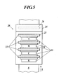
- a plurality of recording heads 21 for color inks of, for example, yellow (Y), magenta (M), cyan (C) and black (k), are arranged in parallel in a conveying direction Z of the recording medium S indicated by an arrow Y (shown).
- a material of the recording medium S, ink types, and the like are similar to those of the embodiment.
- a first light irradiation device 22 including a first light source 23 to emit light having an emission spectrum of a relatively long peak wavelength is arranged between each of the recording heads 21, and a light trap 24 is disposed between the recording head 21 and the first light irradiation device 22.
- a second light irradiation device 25 is arranged on a rear end side of the recording head 21 in a moving direction relative to the recording medium S, i.e., a most downstream side in the conveying direction Z of the recording medium S when seen from a static system of the recording head 21.
- the second light irradiation device 25 includes a second light source 26 to emit light having a second emission spectrum of a relatively short peak wavelength.
- a relation between the lights respectively emitted from the first and second light sources 23 and 26 of the first and second light irradiation devices 22 and 25 is similar to that of the embodiment.
- the modified light irradiation device shown in FIG. 4 in the ink jet recording apparatus 1 of the serial head type can be applied to the ink jet recording apparatus 20 of the line head type.
- recording heads for jetting the same type of ink can be configured by combining a plurality of recording heads.
- the recording head, the light irradiation device, the light trap, and the like can be modified within the scope of the present invention.
- this ink jet recording apparatus first, light having a peak wavelength on a long wavelength side which is not to be scattered easily by pigments of the ink is applied to the ink landed on the recording medium having an ink absorbability.
- the light surely reaches the inside of the ink to harden or thicken the ink from the inside, whereby spreading of the ink started to permeate the recording medium in the surface or thickness direction of the recording medium is surely stopped.
- blocking of spreading of the ink in the surface direction of the recording medium enables sure prevention of ink blotting, and effective prevention of color mixing with an adjacent ink.
- blocking of spreading of the ink in the thickness direction of the recording medium enables ink print through. As a result, a high-definition and high-quality image having no ink blotting, print through or color mixing can be obtained.
- the ink is hardened more and its surface is surely hardened.
- resistance to ink abrasion i.e., abrasion resistance
- abrasion resistance can be increased, and a high-quality image of high abrasion resistance can be obtained.
- the lights having the first and second emission spectrums are ultraviolet rays.
- the first and second light sources are both light sources to emit ultraviolet rays
- easily handled well-known light sources can be used, facilitating deciding and adjusting of a corresponding ink composition.
- the light having the second emission spectrum is an ultraviolet ray whose peak wavelength is 280 nm or less and belongs to a short wavelength ultraviolet region.
- the ultraviolet ray having a peak wavelength at 280 nm or less belonging to so-called short wavelength ultraviolet region (UV-C area) is emitted from the second light source to the ink.
- UV-C area so-called short wavelength ultraviolet region
- each of the first and second light sources includes a light emitting diode (LED).
- LED light emitting diode
- the LED has an advantage that lighting is instantaneous and a life is long.
- the necessity of time for warming-up the light sources is eliminated to increase operation efficiency of the ink jet recording apparatus.
- the light sources are used long, running costs of the apparatus can be reduced.
- the ink jet recording apparatus includes a plurality of the recording heads, and the first light source is disposed at least between each two adjacent recording heads.
- the ink landed on the recording medium can surely receive the light from the first light source before it receives the light from the second light source, thereby exhibiting effects of the invention more surely.
- a distance between the nozzle of the recording head and the first light source can be designed constant for the recording heads.
- levels of ink spreading on the recording medium can be set equal among all the recording heads, enabling acquisition of a higher-quality image.
- the second light source is disposed in the rear end side of the recording head in a moving direction relative to the recording medium.
- the ink landed on the recording medium lastly receives the light from the second light source after it receives the light from the first light source, thereby exhibiting effects of the invention more surely.
- the light sources three types of light sources were used. Specifically, an LED to emit light having an emission spectrum of a peak wavelength at about 365 nm and a half-value width of about 10 nm was used as a light source A, an excimer lamp to emit light having an emission spectrum of a peak wavelength at about 308 nm was used as a light source B, and a low-pressure mercury lamp having a strong emission spectrum at about 254 nm was used as a light source C.
- Table 1 shows an experiment result.
- “A ⁇ B” indicates a case in which the light source A is used as the first light source 12 and the light source B is used as the second light source 15.
- ink hardening levels are determined as follows based on viewing and touching sense of inks recorded in the recording medium S:
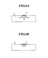
- the light first emitted from the first light source 12 to the ink landed on the recording medium S is a short wavelength light, as shown in FIG. 6A , while a surface of ink I is hardened, the inside of the ink I is not sufficiently hardened, resulting in permeation of an unhardened ink through the recording medium S.
- the light emitted from the first light source 12 is a long wavelength light, as shown in FIG. 6B , the light reaches the inside of the ink I to accurately harden or thicken the ink I from the inside.
- a very good result is obtained when the short wavelength light source C is used as the second light source 15, and a good result is generally obtained when the light source B is used.
- a light source having a peak wavelength of an emission spectrum in a wavelength area of 280 nm or less which is a so-called short wavelength ultraviolet region is preferably used. It is more preferable if a peak wavelength is 254 nm or less as in the case of the light source C.
- a preferable difference in peak wavelength between the first and second light sources 12 and 15 is 50 nm or more at the lowest, and 100 nm or more is more preferable.
Landscapes
- Health & Medical Sciences (AREA)
- General Health & Medical Sciences (AREA)
- Toxicology (AREA)
- Ink Jet (AREA)
- Ink Jet Recording Methods And Recording Media Thereof (AREA)
Applications Claiming Priority (1)
| Application Number | Priority Date | Filing Date | Title |
|---|---|---|---|
| JP2006254394A JP2008073916A (ja) | 2006-09-20 | 2006-09-20 | インクジェット記録装置 |
Publications (3)
| Publication Number | Publication Date |
|---|---|
| EP1958778A2 true EP1958778A2 (fr) | 2008-08-20 |
| EP1958778A3 EP1958778A3 (fr) | 2010-10-06 |
| EP1958778B1 EP1958778B1 (fr) | 2014-12-24 |
Family
ID=39188125
Family Applications (1)
| Application Number | Title | Priority Date | Filing Date |
|---|---|---|---|
| EP07253710.3A Not-in-force EP1958778B1 (fr) | 2006-09-20 | 2007-09-19 | Appareil d'enregistrement à jet d'encre |
Country Status (3)
| Country | Link |
|---|---|
| US (1) | US8042929B2 (fr) |
| EP (1) | EP1958778B1 (fr) |
| JP (1) | JP2008073916A (fr) |
Cited By (2)
| Publication number | Priority date | Publication date | Assignee | Title |
|---|---|---|---|---|
| US8097176B2 (en) * | 2006-01-19 | 2012-01-17 | Ikonics Corporation | Digital mold texturizing methods, materials, and substrates |
| EP2445722B1 (fr) | 2009-06-25 | 2015-10-28 | Sericol Limited | Procédé d'impression |
Families Citing this family (21)
| Publication number | Priority date | Publication date | Assignee | Title |
|---|---|---|---|---|
| JP2008188983A (ja) * | 2006-12-25 | 2008-08-21 | Seiko Epson Corp | 紫外線照射装置および該紫外線照射装置を用いた記録装置、ならびに記録方法 |
| JP4979719B2 (ja) * | 2009-02-04 | 2012-07-18 | 株式会社ミヤコシ | インクジェット記録装置 |
| JP2011079157A (ja) * | 2009-10-05 | 2011-04-21 | Ushio Inc | 光源装置 |
| JP5682750B2 (ja) | 2010-03-30 | 2015-03-11 | セイコーエプソン株式会社 | インクジェット記録装置およびインクジェット記録方法 |
| JP5598122B2 (ja) | 2010-07-09 | 2014-10-01 | セイコーエプソン株式会社 | インクジェット記録方法およびインクジェット記録装置 |
| JP5632670B2 (ja) * | 2010-07-27 | 2014-11-26 | 富士フイルム株式会社 | インクジェット記録方法 |
| JP2014076639A (ja) * | 2012-09-24 | 2014-05-01 | Mimaki Engineering Co Ltd | 印刷方法及び印刷装置 |
| JP6117526B2 (ja) * | 2012-11-22 | 2017-04-19 | 株式会社ミマキエンジニアリング | 印刷方法 |
| EP3013593A1 (fr) * | 2013-06-26 | 2016-05-04 | OCE-Technologies B.V. | Procédé pour appliquer une image au moyen d'une encre à changement de phase radiodurcissable |
| JP2015202687A (ja) * | 2014-04-16 | 2015-11-16 | 株式会社ミマキエンジニアリング | インクジェット印刷装置およびインクジェット印刷方法 |
| US10180248B2 (en) | 2015-09-02 | 2019-01-15 | ProPhotonix Limited | LED lamp with sensing capabilities |
| EP3210761A1 (fr) | 2016-01-25 | 2017-08-30 | Fuji Xerox Co., Ltd | Appareil de façonnage |
| US20170246795A1 (en) | 2016-02-29 | 2017-08-31 | Fuji Xerox Co., Ltd. | Shaping apparatus |
| JP6825225B2 (ja) | 2016-04-27 | 2021-02-03 | セイコーエプソン株式会社 | 印刷装置 |
| JP6876915B2 (ja) * | 2016-07-07 | 2021-05-26 | 富士フイルムビジネスイノベーション株式会社 | 造形装置 |
| JP7110238B2 (ja) * | 2017-05-22 | 2022-08-01 | ザイコン・マニュファクチュアリング・ナムローゼ・フェンノートシャップ | インクまたはトナー層の硬化方法および硬化ユニットを備えたプリントシステム |
| NL2019152B1 (en) * | 2017-06-30 | 2019-01-14 | Xeikon Mfg Nv | Method for curing of an ink or toner layer and printing system with curing unit |
| JP7355543B2 (ja) * | 2019-07-26 | 2023-10-03 | ローランドディー.ジー.株式会社 | インクジェットプリンタ |
| IT202100032903A1 (it) * | 2021-12-29 | 2023-06-29 | Elmag Spa | Impianto di verniciatura perfezionato e metodo di verniciatura |
| JP7833325B2 (ja) * | 2022-03-31 | 2026-03-19 | 三菱重工機械システム株式会社 | 印刷装置 |
| JP2023176509A (ja) * | 2022-05-31 | 2023-12-13 | コニカミノルタ株式会社 | 硬化膜の製造方法および硬化膜の製造装置 |
Citations (2)
| Publication number | Priority date | Publication date | Assignee | Title |
|---|---|---|---|---|
| JPH06200204A (ja) | 1992-12-28 | 1994-07-19 | Brother Ind Ltd | 熱溶融性インク及びそれを用いたインクジェット記録装置 |
| EP1428668A2 (fr) | 2002-12-12 | 2004-06-16 | Konica Minolta Holdings, Inc. | Imprimante à jet d'encre |
Family Cites Families (18)
| Publication number | Priority date | Publication date | Assignee | Title |
|---|---|---|---|---|
| US6561640B1 (en) * | 2001-10-31 | 2003-05-13 | Xerox Corporation | Systems and methods of printing with ultraviolet photosensitive resin-containing materials using light emitting devices |
| US6536889B1 (en) * | 2001-10-31 | 2003-03-25 | Xerox Corporation | Systems and methods for ejecting or depositing substances containing multiple photointiators |
| US6786589B2 (en) * | 2002-03-27 | 2004-09-07 | Konica Corporation | Ink jet printer, ink jet head, and image forming method |
| US6783227B2 (en) * | 2002-03-27 | 2004-08-31 | Konica Corporation | Inkjet printer having an active ray source |
| JP4075444B2 (ja) * | 2002-04-24 | 2008-04-16 | コニカミノルタホールディングス株式会社 | インクジェット記録装置及び記録方法 |
| JP2004034667A (ja) * | 2002-07-08 | 2004-02-05 | Konica Minolta Holdings Inc | インクジェットプリンタ |
| JP2004082452A (ja) * | 2002-08-26 | 2004-03-18 | Konica Minolta Holdings Inc | インクジェット画像形成方法 |
| US7211299B2 (en) * | 2003-01-09 | 2007-05-01 | Con-Trol-Cure, Inc. | UV curing method and apparatus |
| JP4345341B2 (ja) * | 2003-04-17 | 2009-10-14 | コニカミノルタエムジー株式会社 | インクジェットプリンタ |
| JP2004359715A (ja) * | 2003-06-02 | 2004-12-24 | Konica Minolta Medical & Graphic Inc | 光硬化型インク並びにこれを用いる画像記録装置及び画像記録方法 |
| EP1498274B1 (fr) * | 2003-07-15 | 2006-04-05 | Konica Minolta Medical & Graphic Inc. | Imprimante à jet d'encre avec encre à sèchage ultraviolet |
| JP2005144679A (ja) * | 2003-11-11 | 2005-06-09 | Roland Dg Corp | インクジェットプリンタ |
| US20050156964A1 (en) * | 2004-01-19 | 2005-07-21 | Konica Minolta Medical & Graphic, Inc. | Ink-jet recording apparatus |
| JP2006181805A (ja) * | 2004-12-27 | 2006-07-13 | Konica Minolta Medical & Graphic Inc | インクジェット記録装置 |
| JP4311364B2 (ja) * | 2005-03-18 | 2009-08-12 | セイコーエプソン株式会社 | 液滴吐出装置 |
| US9275887B2 (en) * | 2006-07-20 | 2016-03-01 | Applied Materials, Inc. | Substrate processing with rapid temperature gradient control |
| US7794075B2 (en) * | 2006-12-25 | 2010-09-14 | Seiko Epson Corporation | Ultraviolet ray irradiation device, recording apparatus using the ultraviolet ray irradiation device, and recording method |
| US8287116B2 (en) * | 2008-02-14 | 2012-10-16 | Hewlett-Packard Development Company, L.P. | Printing apparatus and method |
-
2006
- 2006-09-20 JP JP2006254394A patent/JP2008073916A/ja active Pending
-
2007
- 2007-09-19 EP EP07253710.3A patent/EP1958778B1/fr not_active Not-in-force
- 2007-09-20 US US11/858,500 patent/US8042929B2/en active Active
Patent Citations (3)
| Publication number | Priority date | Publication date | Assignee | Title |
|---|---|---|---|---|
| JPH06200204A (ja) | 1992-12-28 | 1994-07-19 | Brother Ind Ltd | 熱溶融性インク及びそれを用いたインクジェット記録装置 |
| EP1428668A2 (fr) | 2002-12-12 | 2004-06-16 | Konica Minolta Holdings, Inc. | Imprimante à jet d'encre |
| JP2004188864A (ja) | 2002-12-12 | 2004-07-08 | Konica Minolta Holdings Inc | インクジェットプリンタ |
Cited By (3)
| Publication number | Priority date | Publication date | Assignee | Title |
|---|---|---|---|---|
| US8097176B2 (en) * | 2006-01-19 | 2012-01-17 | Ikonics Corporation | Digital mold texturizing methods, materials, and substrates |
| US9044986B2 (en) | 2006-01-19 | 2015-06-02 | Ikonics Corporation | Digital mold texturizing methods, materials, and substrates |
| EP2445722B1 (fr) | 2009-06-25 | 2015-10-28 | Sericol Limited | Procédé d'impression |
Also Published As
| Publication number | Publication date |
|---|---|
| JP2008073916A (ja) | 2008-04-03 |
| US20080068431A1 (en) | 2008-03-20 |
| US8042929B2 (en) | 2011-10-25 |
| EP1958778B1 (fr) | 2014-12-24 |
| EP1958778A3 (fr) | 2010-10-06 |
Similar Documents
| Publication | Publication Date | Title |
|---|---|---|
| EP1958778B1 (fr) | Appareil d'enregistrement à jet d'encre | |
| JP5131197B2 (ja) | インクジェット記録装置 | |
| US7510277B2 (en) | Image forming apparatus and method | |
| EP2452823B1 (fr) | Appareil d'enregistrement par jet d'encre et procédé de formation d'images | |
| US7794076B2 (en) | Ultraviolet ray irradiation device, recording apparatus using the ultraviolet ray irradiation device, and recording method | |
| US8025388B2 (en) | Image forming apparatus and image forming method with decreased image transfer disturbance | |
| US7794075B2 (en) | Ultraviolet ray irradiation device, recording apparatus using the ultraviolet ray irradiation device, and recording method | |
| JP4269672B2 (ja) | インクジェットプリンタ | |
| US7922318B2 (en) | Inkjet recording apparatus | |
| US7159963B2 (en) | Image recording apparatus with wipe unit and nozzle maintenance unit | |
| US8814343B2 (en) | Liquid ejecting apparatus | |
| JP2009226692A (ja) | インクジェットプリンタ | |
| CN102821960A (zh) | 喷墨打印机 | |
| JP2008188983A (ja) | 紫外線照射装置および該紫外線照射装置を用いた記録装置、ならびに記録方法 | |
| JP2009056695A (ja) | インクジェット記録装置 | |
| JP2004237588A (ja) | インクジェット記録装置 | |
| JP5378194B2 (ja) | インクジェット式画像形成装置 | |
| JP4877063B2 (ja) | 光照射装置および液体噴射装置 | |
| JP4615960B2 (ja) | 画像記録装置及びその駆動方法 | |
| JP2004167968A (ja) | インクジェットプリンタ | |
| JP2008105268A (ja) | 光硬化型インクのインクジェット画像形成装置、及びインクジェット画像形成方法 | |
| JP4453269B2 (ja) | インクジェットプリンタ | |
| JP7312119B2 (ja) | インクジェットプリンタおよびインクジェットプリンタの制御方法 | |
| JP2011062996A (ja) | 液体吐出装置 | |
| JP2005238733A (ja) | インクジェット記録装置 |
Legal Events
| Date | Code | Title | Description |
|---|---|---|---|
| PUAI | Public reference made under article 153(3) epc to a published international application that has entered the european phase |
Free format text: ORIGINAL CODE: 0009012 |
|
| AK | Designated contracting states |
Kind code of ref document: A2 Designated state(s): AT BE BG CH CY CZ DE DK EE ES FI FR GB GR HU IE IS IT LI LT LU LV MC MT NL PL PT RO SE SI SK TR |
|
| AX | Request for extension of the european patent |
Extension state: AL BA HR MK RS |
|
| PUAL | Search report despatched |
Free format text: ORIGINAL CODE: 0009013 |
|
| AK | Designated contracting states |
Kind code of ref document: A3 Designated state(s): AT BE BG CH CY CZ DE DK EE ES FI FR GB GR HU IE IS IT LI LT LU LV MC MT NL PL PT RO SE SI SK TR |
|
| AX | Request for extension of the european patent |
Extension state: AL BA HR MK RS |
|
| 17P | Request for examination filed |
Effective date: 20110406 |
|
| AKX | Designation fees paid |
Designated state(s): DE GB |
|
| GRAP | Despatch of communication of intention to grant a patent |
Free format text: ORIGINAL CODE: EPIDOSNIGR1 |
|
| INTG | Intention to grant announced |
Effective date: 20140725 |
|
| GRAS | Grant fee paid |
Free format text: ORIGINAL CODE: EPIDOSNIGR3 |
|
| GRAA | (expected) grant |
Free format text: ORIGINAL CODE: 0009210 |
|
| AK | Designated contracting states |
Kind code of ref document: B1 Designated state(s): DE GB |
|
| REG | Reference to a national code |
Ref country code: GB Ref legal event code: FG4D |
|
| REG | Reference to a national code |
Ref country code: DE Ref legal event code: R096 Ref document number: 602007039780 Country of ref document: DE Effective date: 20150219 |
|
| REG | Reference to a national code |
Ref country code: DE Ref legal event code: R097 Ref document number: 602007039780 Country of ref document: DE |
|
| PLBE | No opposition filed within time limit |
Free format text: ORIGINAL CODE: 0009261 |
|
| STAA | Information on the status of an ep patent application or granted ep patent |
Free format text: STATUS: NO OPPOSITION FILED WITHIN TIME LIMIT |
|
| 26N | No opposition filed |
Effective date: 20150925 |
|
| PGFP | Annual fee paid to national office [announced via postgrant information from national office to epo] |
Ref country code: DE Payment date: 20190903 Year of fee payment: 13 |
|
| PGFP | Annual fee paid to national office [announced via postgrant information from national office to epo] |
Ref country code: GB Payment date: 20190919 Year of fee payment: 13 |
|
| REG | Reference to a national code |
Ref country code: DE Ref legal event code: R119 Ref document number: 602007039780 Country of ref document: DE |
|
| GBPC | Gb: european patent ceased through non-payment of renewal fee |
Effective date: 20200919 |
|
| PG25 | Lapsed in a contracting state [announced via postgrant information from national office to epo] |
Ref country code: DE Free format text: LAPSE BECAUSE OF NON-PAYMENT OF DUE FEES Effective date: 20210401 |
|
| PG25 | Lapsed in a contracting state [announced via postgrant information from national office to epo] |
Ref country code: GB Free format text: LAPSE BECAUSE OF NON-PAYMENT OF DUE FEES Effective date: 20200919 |