EP1958865B1 - Fixation de dérailleur avant - Google Patents
Fixation de dérailleur avant Download PDFInfo
- Publication number
- EP1958865B1 EP1958865B1 EP20080002615 EP08002615A EP1958865B1 EP 1958865 B1 EP1958865 B1 EP 1958865B1 EP 20080002615 EP20080002615 EP 20080002615 EP 08002615 A EP08002615 A EP 08002615A EP 1958865 B1 EP1958865 B1 EP 1958865B1
- Authority
- EP
- European Patent Office
- Prior art keywords
- front derailleur
- screw
- clamping band
- basic body
- fitting manner
- Prior art date
- Legal status (The legal status is an assumption and is not a legal conclusion. Google has not performed a legal analysis and makes no representation as to the accuracy of the status listed.)
- Ceased
Links
- 239000002131 composite material Substances 0.000 claims description 5
- RTAQQCXQSZGOHL-UHFFFAOYSA-N Titanium Chemical compound [Ti] RTAQQCXQSZGOHL-UHFFFAOYSA-N 0.000 claims description 4
- 239000000835 fiber Substances 0.000 claims description 4
- 239000000463 material Substances 0.000 claims description 4
- 239000010936 titanium Substances 0.000 claims description 4
- 229910052719 titanium Inorganic materials 0.000 claims description 4
- 229910052782 aluminium Inorganic materials 0.000 claims description 3
- XAGFODPZIPBFFR-UHFFFAOYSA-N aluminium Chemical compound [Al] XAGFODPZIPBFFR-UHFFFAOYSA-N 0.000 claims description 3
- 239000003562 lightweight material Substances 0.000 claims description 3
- 229920003023 plastic Polymers 0.000 claims description 3
- 239000004033 plastic Substances 0.000 claims description 3
- 229910001220 stainless steel Inorganic materials 0.000 claims description 3
- 239000010935 stainless steel Substances 0.000 claims description 3
- 239000004411 aluminium Substances 0.000 claims 1
- OKTJSMMVPCPJKN-UHFFFAOYSA-N Carbon Chemical compound [C] OKTJSMMVPCPJKN-UHFFFAOYSA-N 0.000 description 1
- 229920000049 Carbon (fiber) Polymers 0.000 description 1
- 230000006978 adaptation Effects 0.000 description 1
- 230000005540 biological transmission Effects 0.000 description 1
- 229910052799 carbon Inorganic materials 0.000 description 1
- 239000004917 carbon fiber Substances 0.000 description 1
- 230000001419 dependent effect Effects 0.000 description 1
- 230000000694 effects Effects 0.000 description 1
- 229920002457 flexible plastic Polymers 0.000 description 1
- 238000009434 installation Methods 0.000 description 1
- 230000003993 interaction Effects 0.000 description 1
- 230000013011 mating Effects 0.000 description 1
- 229910052751 metal Inorganic materials 0.000 description 1
- 239000002184 metal Substances 0.000 description 1
- VNWKTOKETHGBQD-UHFFFAOYSA-N methane Chemical compound C VNWKTOKETHGBQD-UHFFFAOYSA-N 0.000 description 1
- 230000035515 penetration Effects 0.000 description 1
- 239000007787 solid Substances 0.000 description 1
- 239000013585 weight reducing agent Substances 0.000 description 1
Images


Classifications
-
- B—PERFORMING OPERATIONS; TRANSPORTING
- B62—LAND VEHICLES FOR TRAVELLING OTHERWISE THAN ON RAILS
- B62M—RIDER PROPULSION OF WHEELED VEHICLES OR SLEDGES; POWERED PROPULSION OF SLEDGES OR SINGLE-TRACK CYCLES; TRANSMISSIONS SPECIALLY ADAPTED FOR SUCH VEHICLES
- B62M9/00—Transmissions characterised by use of an endless chain, belt, or the like
- B62M9/04—Transmissions characterised by use of an endless chain, belt, or the like of changeable ratio
- B62M9/06—Transmissions characterised by use of an endless chain, belt, or the like of changeable ratio using a single chain, belt, or the like
- B62M9/10—Transmissions characterised by use of an endless chain, belt, or the like of changeable ratio using a single chain, belt, or the like involving different-sized wheels, e.g. rear sprocket chain wheels selectively engaged by the chain, belt, or the like
- B62M9/12—Transmissions characterised by use of an endless chain, belt, or the like of changeable ratio using a single chain, belt, or the like involving different-sized wheels, e.g. rear sprocket chain wheels selectively engaged by the chain, belt, or the like the chain, belt, or the like being laterally shiftable, e.g. using a rear derailleur
- B62M9/131—Front derailleurs
- B62M9/135—Mounting the derailleur on the frame
Definitions
- the present invention relates, according to the preamble of the main claim, the Kettenumwerferbefestist a front derailleur on the bicycle frame.
- the Kettenumwerfer a bicycle, especially the front derailleur is mainly clamped with a clamp directly to the frame tube or screwed to a arranged on the frame Anlötsockel.
- the clamp connection is usually made of a firmly connected to the chain derailleur and a pivotable cup-shaped clamp half. If the Kettenumwerfer be screwed to an existing Anlötsockel, so the predefined position on the frame does not always allow the correct fixation of the Kettenumwerfers with regard to the interaction of chainring and Kettenumwerfer.
- the correct distance from the frame and the correct height of the chain derailleur matched to the corresponding chainring set requires additional adaptation measures.
- a Kettenumwerfer is shown with an adapter for variable attachment to a Anlötsockel.
- This adapter allows the attachment of the derailleur at the correct distance to the bicycle frame and in at least two predetermined height positions. This is accomplished by a base body having at least two attachment positions for attaching the retaining screw for the chain derailleur.
- this chain derailleur with variable attachment is suitable for attaching the derailleur in several height positions on Anlötsockel, but requires an already existing on the frame Anlötsockel.
- the DE 3515589 C2 shows a front derailleur with a strap attachment.
- the clamping band is angled at the ends and each equipped with a transverse arc and an engagement hole. After this fairly stiff clamping band has been pressed around the frame, the band ends are threaded into a recess on the chain derailleur. By tightening a spring-loaded, sharp-edged nut, which engages in the engagement holes at the belt ends, the clamping band is clamped by means of a clamping screw. Due to the grooves, which allow a penetration of the sharp-edged nut through the engagement bore a positive clamping force transmission is achieved.
- the JP 2006132585 A discloses a suitable as Kettenumwerferbefest only mounting clamp according to the preamble of claim 1.
- the present invention seeks to provide a Kettenumwerfer that can be used universally independent of the frame tube cross-section and of a Anlötsockel in any height position.
- a cost-effective, lightweight, conformable and yet stable attachment of the front derailleur is sought.
- This inventive Kettenumwerferbefest Trent consists of a body for fixing the Kettenumwerfers means of a fastening screw, an elastic clamping band with a screw holder and a clamp screw.
- the fixing screw fixes both the Kettenumwerfer and the one end of the clamping band on the body.
- the clamping band is screwed or clamped on the base body via the clamp screw, which is guided in a screw holder at the other end of the band.
- the attachment of the body to the corresponding frame section is non-positively. For this purpose, the concave body portion lays against the frame tube and is pressed by the clamping band.
- the chain derailleur is received in a form-fitting manner, for this purpose the chain derailleur mount on the main body engages around the corresponding contact contour on the chain derailleur and supports it torsionally together with the fastening screw.
- the clamping band surrounds or wraps around the screw holder and forms a positive connection with it. In this case, the folded over to an eyelet end can be additionally fixed with a fastening rivet on the clamping band.
- the clamp and fixing screws are arranged on the base body so that they are accessible from the front in the assembled state of the derailleur on the bicycle.
- the fastening screw and the clamp screw are arranged on different levels on the base body and their center lines extend in an angular range between 60 ° and 120 ° preferably at about a right angle to each other. Since the two screws and thus also the two clamping belt ends are not on one level but are offset relative to one another on the base body, the clamping belt runs quasi on a helical line around the frame or the frame tube.
- the base body and the screw holder made of a lightweight material such as aluminum, plastic or a fiber composite material and the clamping band of a tensile, strain-resistant material such as metal in particular stainless steel, titanium or also from a fiber composite material.
- This Kettenumwerferbefestist with the stable body and the flexible clamping band is universally applicable to almost any frame and is characterized by little components and low installation costs.
- the positive reception for the Kettenumwerfer and the positive support of the body on the bicycle frame ensures high reliability of Kettenumwerfers.
- the Kettenumwerferbefestist is also suitable for use on racing bikes.
- FIG. 1 shows the preassembled Kettenumwerferbefest Trent with the main body 1, the clamping band 2, the screw holder 3, the clamp screw 4 and the fixing screw 5.
- the main body 1 is a concave contour 6 as a mating surface equipped to the corresponding frame surface.
- the Kettenumwerfer is received positively by the Kettenumwerferability 7 on the base body 1.
- the Kettenumwerferability 7 engages around a corresponding contact contour on the Kettenumwerfer, also this is screwed to the mounting screw 5 on the base body 1.
- the height of the Kettenumwerferability 7 and the main body 1 is greater than the width of the clamping band 2 and supports the initiated by the Kettenumwerfer switching moments on the frame.
- the clamping band 2 made of stainless steel or titanium, is screwed with one end by means of the fastening screw 5 on the base body 1 together with the Kettenumwerfer.
- the other end of the clamping band 2 is bent around the screw holder 3 and screwed with the clamp screw 4 on the base body 1.
- the screw-in thread for the clamp screw 4 can be arranged either in the screw holder 3 or in the main body 1.
- the Einschraubgewinde for the clamp screw 4 in the screw holder 3 so are the two screw heads of the clamp and mounting screw 4.5 on the base body 1 in close proximity to each other and can be easily screwed from the front.
- the clamping band 2 runs on a helical line around the frame tube, since the fastening screw 5, which fixes one end of the clamping band 2 on the base body 1, not on the same level as the clamp screw 4, with the the other end is attached to the base body 1.
- the clamping band 2 is provided with a cutout 8 for weight reduction. It is so elastic that it tightly clings to the convex contour of the frame tube during tightening by the clamp screw 4.
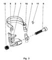
- FIG. 2 shows the items of the chain derailleur attachment.
- the main body 1 is the core piece on which the clamping band 2 are screwed to the fastening screw and the clamp screw 4.
- the clamping band 2 is angled at one end and provided with one or more spaced-apart holes for the implementation of the fastening screw.
- Several holes on the end of the clamp allow a first adjustment of the clamping band to different frame tube cross-sections. This end is threaded through a recess 9 on the base body 1 and screwed together with the fixing screw, which dips into one of the holes, together with the base body 1 on the chain derailleur.
- a portion of the base body 1 between the recess 9 and a Outside edge on the base body 1 is located after assembly between clamping band 2 and frame tube.
- the other end is bent around the screw holder 3 and forms an eyelet 10 which is fixed with a fastening rivet 11 on the clamping band 2.
- the clamping band 2 is thus held positively at both ends.
- the screw holder 3 is received by the eyelet 10 is equipped with a bore for receiving the clamp screw 4.
- the clamping band 2 is tightened by screwing the clamp screw 4.
- FIG. 3 shows a complete Kettenumwerfer 14 on the frame tube 13.
- the Kettenumwerfer 14 is positively against the Kettenumwerferability 7 of the body 1 and is fixed by the mounting screw 5.
- the clamping band is screwed to the Grundsammlung1 over the clamp screw 4, which is guided in the screw holder 3.
- the fastening screw 5 and the clamp screw 4 are located on two different levels on the base body 1 and their center lines are approximately at right angles to each other.
- the contact surface of the main body 1 on the frame tube 13 has a concave contour 6.
- the height of the contact surface of the base body 1 on the frame tube 13 is greater than the clamping band width or the length of the screw holder. 3
Landscapes
- Engineering & Computer Science (AREA)
- Chemical & Material Sciences (AREA)
- Combustion & Propulsion (AREA)
- Transportation (AREA)
- Mechanical Engineering (AREA)
- Clamps And Clips (AREA)
- Mutual Connection Of Rods And Tubes (AREA)
Claims (8)
- Fixation de dérailleur pour le montage d'un dérailleur (14) sur le cadre d'une bicyclette avec un ruban de serrage (2) qui est reçu par engagement par correspondance géométrique aux deux extrémités et qui est serré avec une vis de collier de serrage (4),
la fixation de dérailleur se composant d'un corps de base (1) qui est monté au moyen d'au moins un élément de connexion desserrable par exemple d'une vis de fixation (5) sur le dérailleur (14) et d'un ruban de serrage (2) élastique qui est connecté à une extrémité par engagement par correspondance géométrique au corps de base (1) et qui reçoit par engagement par correspondance géométrique à l'autre extrémité soit directement la vis de collier de serrage (4) soit par le biais d'un dispositif de fixation de vis (3), la vis de collier de serrage (4) reliant le corps de base (1) et le ruban de serrage (2) ou serrant le ruban de serrage (2) autour du tube du cadre (13),
caractérisée en ce que
l'une des extrémités du ruban de serrage (2) est coudée et est munie d'au moins un trou pour la vis de fixation (5), qui fixe cette extrémité sur le corps de base (1) conjointement avec le dérailleur (14),
en ce l'une des extrémités du ruban de serrage (2) est enfilée à travers un évidement (9) sur le corps de base (1) et le ruban de serrage (2) enveloppe le tube de cadre (13) suivant une courbe hélicoïdale,
un dérailleur (14) s'appliquant, dans l'état monté, par engagement par correspondance géométrique contre un logement de dérailleur (7) du corps de base (1), et pouvant être fixé par la vis de fixation (5). - Fixation de dérailleur selon la revendication 1,
caractérisée en ce que
l'autre extrémité du ruban de serrage (2) forme un oeillet (10) pour recevoir par engagement par correspondance géométrique le support de vis (3) et est munie d'un perçage pour le passage de la vis de collier de serrage (4). - Fixation de dérailleur selon la revendication 1,
caractérisée en ce que
le corps de base (1) reçoit par engagement par correspondance géométrique la vis de fixation (5) et la vis de collier de serrage (4) par exemple dans un trou ou un trou fileté, lesquels trous sont disposés dans des plans différents. - Fixation de dérailleur selon la revendication 2,
caractérisée en ce que
les axes médians de la vis de fixation (5) et de la vis de collier de serrage (4) se situent sur un même plan ou sur des plans différents, et s'étendent l'un par rapport à l'autre dans une plage angulaire de 60° à 120°, de préférence suivant approximativement un angle droit. - Fixation de dérailleur selon la revendication 2,
caractérisée en ce que
la vis de collier de serrage (4) est vissée soit dans un trou fileté sur le support de vis (3) soit dans un trou fileté ou un insert fileté (12) sur le corps de base (1) pour serrer le ruban de serrage (2). - Fixation de dérailleur selon la revendication 1,
caractérisée en ce que
le corps de base (1) s'applique avec un contour concave (6) sur le tube de cadre (13) et entoure par engagement par correspondance géométrique avec le logement de dérailleur (7) le dérailleur (14) au niveau d'un contour correspondant et celui-ci est fixé au corps de base (1) avec la vis de fixation (5). - Fixation de dérailleur selon la revendication 6,
caractérisée en ce que
la hauteur du corps de base (1) ou de la face d'appui concave, pour un meilleur support des couples de changement de vitesse se produisant, est considérablement plus grande que la largeur du ruban de serrage (2). - Fixation de dérailleur selon la revendication 1,
caractérisée en ce que
le corps de base (1) se compose d'un matériau léger, comme de l'aluminium, du plastique ou un matériau composite renforcé par des fibres, et le ruban de serrage (2) se compose d'un matériau résistant à la traction, comme de l'acier surfin, du titane ou un matériau composite renforcé par des fibres.
Applications Claiming Priority (1)
| Application Number | Priority Date | Filing Date | Title |
|---|---|---|---|
| DE102007008326A DE102007008326A1 (de) | 2007-02-16 | 2007-02-16 | Kettenumwerferbefestigung |
Publications (3)
| Publication Number | Publication Date |
|---|---|
| EP1958865A2 EP1958865A2 (fr) | 2008-08-20 |
| EP1958865A3 EP1958865A3 (fr) | 2009-09-30 |
| EP1958865B1 true EP1958865B1 (fr) | 2011-10-19 |
Family
ID=39478171
Family Applications (1)
| Application Number | Title | Priority Date | Filing Date |
|---|---|---|---|
| EP20080002615 Ceased EP1958865B1 (fr) | 2007-02-16 | 2008-02-13 | Fixation de dérailleur avant |
Country Status (4)
| Country | Link |
|---|---|
| EP (1) | EP1958865B1 (fr) |
| CN (1) | CN101244749B (fr) |
| DE (1) | DE102007008326A1 (fr) |
| TW (1) | TWI418492B (fr) |
Families Citing this family (2)
| Publication number | Priority date | Publication date | Assignee | Title |
|---|---|---|---|---|
| DE102008049360A1 (de) | 2008-09-29 | 2010-04-08 | Sram Deutschland Gmbh | Kettenschaltung für ein Fahrrad |
| CN113650495A (zh) * | 2021-08-27 | 2021-11-16 | 江麓机电集团有限公司 | 一种基于钛合金车体的变速箱安装支座 |
Family Cites Families (20)
| Publication number | Priority date | Publication date | Assignee | Title |
|---|---|---|---|---|
| DE825812C (de) * | 1951-11-22 | Lucien Juy Di] on Cote d Or (Frankreich) | Schalteinrichtung fur die Kettenumschal tung an den Kettenradern der Tret kurbel von Fahrradern o dgl | |
| GB577659A (en) * | 1946-04-25 | 1946-05-27 | Adel Prec Products Corp | Universal support for conduits |
| GB666670A (en) * | 1948-09-03 | 1952-02-13 | Juy Lucien Charles Hippolyte | Sliding control for the shifting of a chain in bicycle change speed gears |
| DE847701C (de) * | 1951-03-31 | 1952-08-28 | Lucien Charles Hippolyte Juy | Kettenfuehrung fuer Geschwindigkeitswechselgetriebe mit Ketten-umschaltung, insbesondere fuer Fahrraeder |
| DE1782592U (de) * | 1956-04-10 | 1959-02-05 | Fichtel & Sachs Ag | Kettenumschalter fuer tretkurbelkettenraeder von fahrraedern. |
| FR2294079A1 (fr) * | 1974-12-12 | 1976-07-09 | Shimano Industrial Co | Derailleur avant pour une bicyclette |
| CH653113A5 (de) * | 1981-11-05 | 1985-12-13 | Immanuel Straub | Rohrkupplung sowie verwendung derselben. |
| FR2522609A1 (fr) * | 1981-12-30 | 1983-09-09 | Huret & Fils | Derailleur de pedalier pour cycle |
| JPS5964384U (ja) * | 1982-10-22 | 1984-04-27 | 株式会社津山金属製作所 | 自転車用照明装置の取り付け具 |
| US4477865A (en) * | 1983-10-19 | 1984-10-16 | Tsuyama Manufacturing Company, Ltd. | Mounting device for lighting device for bicycle |
| JPS60234090A (ja) | 1984-05-01 | 1985-11-20 | 株式会社シマノ | 自転車部品の自転車フレ−ムへの取付構造 |
| DE9410177U1 (de) * | 1994-05-10 | 1994-11-10 | Hsu, Yi Hsung, San Chung, Taipeh | Von oben zu betätigende vordere Fahrradkettenschaltung |
| US6146298A (en) * | 1999-03-29 | 2000-11-14 | Shimano, Inc. | Band adapter for front derailleur |
| US20040185975A1 (en) * | 2003-03-20 | 2004-09-23 | Po-Cheng Chen | Chain-poking device for derailleurs |
| DE102004037740A1 (de) | 2004-08-04 | 2006-03-16 | Sram Deutschland Gmbh | Flexibler Schelleneinsatz |
| JP2006132585A (ja) * | 2004-11-02 | 2006-05-25 | Sankyo Kogyo Kk | エアーダクト用吊りバンド |
| CN2769584Y (zh) * | 2004-11-17 | 2006-04-05 | 重庆宗申技术开发研究有限公司 | 便拆卸式抱箍 |
| TWI245004B (en) * | 2005-01-27 | 2005-12-11 | Chenn Daa Co Ltd | Angle-adjustable front speed-changer of bicycles |
| DE102005022381A1 (de) | 2005-05-14 | 2006-11-16 | Sram Deutschland Gmbh | Kettenumwerfer mit variabler Befestigung |
| JP4520954B2 (ja) * | 2005-05-20 | 2010-08-11 | 株式会社キャットアイ | 固定具 |
-
2007
- 2007-02-16 DE DE102007008326A patent/DE102007008326A1/de not_active Withdrawn
-
2008
- 2008-02-13 EP EP20080002615 patent/EP1958865B1/fr not_active Ceased
- 2008-02-15 CN CN2008100055653A patent/CN101244749B/zh not_active Expired - Fee Related
- 2008-02-15 TW TW97105303A patent/TWI418492B/zh active
Also Published As
| Publication number | Publication date |
|---|---|
| EP1958865A2 (fr) | 2008-08-20 |
| EP1958865A3 (fr) | 2009-09-30 |
| TWI418492B (zh) | 2013-12-11 |
| CN101244749A (zh) | 2008-08-20 |
| CN101244749B (zh) | 2012-07-04 |
| DE102007008326A1 (de) | 2008-08-21 |
| TW200916372A (en) | 2009-04-16 |
Similar Documents
| Publication | Publication Date | Title |
|---|---|---|
| EP2217469B1 (fr) | Élément de positionnement | |
| DE9110175U1 (de) | Beschlagteil zur Klemmbefestigung in einer mindestens einseitig hinterschnittenen Profilnut | |
| DE102013014760B4 (de) | Fahrzeugleuchte, insbesondere Fahrzeugrückleuchte, mit einstellbarer Befestigung | |
| EP1087147B1 (fr) | Dispositif de fixation pour éléments en plaques | |
| EP1404987A1 (fr) | Palier caoutchoute, de preference palier de stabilisation et procede pour monter ledit palier | |
| EP2144435A2 (fr) | Caméra et boîtier de caméra | |
| DE202009013592U1 (de) | Lenkervorbau für Fahrradlenker | |
| DE102014012421A1 (de) | Befestigungssystem | |
| EP1958865B1 (fr) | Fixation de dérailleur avant | |
| EP3514434B1 (fr) | Collier de serrage de tuyau | |
| DE29580485U1 (de) | Vorrichtung zum Verbinden von Rohrabschnitten | |
| EP3538728B1 (fr) | Palier rotatif pour battant latéral d'un véhicule | |
| DE10304361A1 (de) | Halter für plattenförmige Bauteile | |
| EP1770823B1 (fr) | Support pour une antenne | |
| WO2008104168A1 (fr) | Raccord de barres profilées | |
| EP2102038B1 (fr) | Ensemble boîtier d'un système essuie-glace à assemblage vissé | |
| DE10102136A1 (de) | Befestigungdsystem | |
| EP3480097B1 (fr) | Élément de serrage destiné à fixer des unités de levier de frein / de changement de vitesse aux guidons de vélo ainsi que unités de levier de frein / de changement de vitesse avec un tel élément de serrage | |
| EP1386833B1 (fr) | Dispositif de fixation d'un garde-boue à bras rayonnants pour une bicyclette | |
| EP1712826A1 (fr) | Armature à collerette et utilisation d'une telle armature à collerette | |
| DE102011050896A1 (de) | Befestigungsvorrichtung | |
| DE202006005375U1 (de) | Vorrichtung zum Justieren eines Baukörpers | |
| DE202011050375U1 (de) | Befestigungsvorrichtung | |
| DE102018122701A1 (de) | Haltersystem zur Befestigung eines Behälters an einem Fahrzeug | |
| DE19622192C1 (de) | Hilfswerkzeug für die Montage von Einrohr- Rohr/Schlauchschellen |
Legal Events
| Date | Code | Title | Description |
|---|---|---|---|
| PUAI | Public reference made under article 153(3) epc to a published international application that has entered the european phase |
Free format text: ORIGINAL CODE: 0009012 |
|
| AK | Designated contracting states |
Kind code of ref document: A2 Designated state(s): AT BE BG CH CY CZ DE DK EE ES FI FR GB GR HR HU IE IS IT LI LT LU LV MC MT NL NO PL PT RO SE SI SK TR |
|
| AX | Request for extension of the european patent |
Extension state: AL BA MK RS |
|
| 111Z | Information provided on other rights and legal means of execution |
Free format text: AT BE BG CH CY CZ DE DK EE ES FI FR GB GR HR HU IE IS IT LT LU LV MC MT NL NO PL PT RO SE SI SK TR Effective date: 20090106 |
|
| PUAL | Search report despatched |
Free format text: ORIGINAL CODE: 0009013 |
|
| AK | Designated contracting states |
Kind code of ref document: A3 Designated state(s): AT BE BG CH CY CZ DE DK EE ES FI FR GB GR HR HU IE IS IT LI LT LU LV MC MT NL NO PL PT RO SE SI SK TR |
|
| AX | Request for extension of the european patent |
Extension state: AL BA MK RS |
|
| 17P | Request for examination filed |
Effective date: 20091021 |
|
| 17Q | First examination report despatched |
Effective date: 20091116 |
|
| AKX | Designation fees paid |
Designated state(s): DE FR NL |
|
| GRAP | Despatch of communication of intention to grant a patent |
Free format text: ORIGINAL CODE: EPIDOSNIGR1 |
|
| GRAS | Grant fee paid |
Free format text: ORIGINAL CODE: EPIDOSNIGR3 |
|
| GRAA | (expected) grant |
Free format text: ORIGINAL CODE: 0009210 |
|
| AK | Designated contracting states |
Kind code of ref document: B1 Designated state(s): DE FR NL |
|
| REG | Reference to a national code |
Ref country code: DE Ref legal event code: R096 Ref document number: 502008005209 Country of ref document: DE Effective date: 20111215 |
|
| REG | Reference to a national code |
Ref country code: NL Ref legal event code: T3 |
|
| PLBE | No opposition filed within time limit |
Free format text: ORIGINAL CODE: 0009261 |
|
| STAA | Information on the status of an ep patent application or granted ep patent |
Free format text: STATUS: NO OPPOSITION FILED WITHIN TIME LIMIT |
|
| 26N | No opposition filed |
Effective date: 20120720 |
|
| REG | Reference to a national code |
Ref country code: DE Ref legal event code: R097 Ref document number: 502008005209 Country of ref document: DE Effective date: 20120720 |
|
| REG | Reference to a national code |
Ref country code: FR Ref legal event code: PLFP Year of fee payment: 9 |
|
| REG | Reference to a national code |
Ref country code: FR Ref legal event code: PLFP Year of fee payment: 10 |
|
| REG | Reference to a national code |
Ref country code: FR Ref legal event code: PLFP Year of fee payment: 11 |
|
| PGFP | Annual fee paid to national office [announced via postgrant information from national office to epo] |
Ref country code: NL Payment date: 20200219 Year of fee payment: 13 Ref country code: DE Payment date: 20200214 Year of fee payment: 13 |
|
| PGFP | Annual fee paid to national office [announced via postgrant information from national office to epo] |
Ref country code: FR Payment date: 20200219 Year of fee payment: 13 |
|
| REG | Reference to a national code |
Ref country code: DE Ref legal event code: R119 Ref document number: 502008005209 Country of ref document: DE |
|
| REG | Reference to a national code |
Ref country code: NL Ref legal event code: MM Effective date: 20210301 |
|
| PG25 | Lapsed in a contracting state [announced via postgrant information from national office to epo] |
Ref country code: NL Free format text: LAPSE BECAUSE OF NON-PAYMENT OF DUE FEES Effective date: 20210301 |
|
| PG25 | Lapsed in a contracting state [announced via postgrant information from national office to epo] |
Ref country code: DE Free format text: LAPSE BECAUSE OF NON-PAYMENT OF DUE FEES Effective date: 20210901 Ref country code: FR Free format text: LAPSE BECAUSE OF NON-PAYMENT OF DUE FEES Effective date: 20210228 |