EP1959023A1 - Batterie sèche alcaline - Google Patents
Batterie sèche alcaline Download PDFInfo
- Publication number
- EP1959023A1 EP1959023A1 EP08150119A EP08150119A EP1959023A1 EP 1959023 A1 EP1959023 A1 EP 1959023A1 EP 08150119 A EP08150119 A EP 08150119A EP 08150119 A EP08150119 A EP 08150119A EP 1959023 A1 EP1959023 A1 EP 1959023A1
- Authority
- EP
- European Patent Office
- Prior art keywords
- negative electrode
- inclusive
- separator
- zinc alloy
- nonwoven fabric
- Prior art date
- Legal status (The legal status is an assumption and is not a legal conclusion. Google has not performed a legal analysis and makes no representation as to the accuracy of the status listed.)
- Granted
Links
Images

Classifications
-
- H—ELECTRICITY
- H01—ELECTRIC ELEMENTS
- H01M—PROCESSES OR MEANS, e.g. BATTERIES, FOR THE DIRECT CONVERSION OF CHEMICAL ENERGY INTO ELECTRICAL ENERGY
- H01M6/00—Primary cells; Manufacture thereof
- H01M6/04—Cells with aqueous electrolyte
- H01M6/06—Dry cells, i.e. cells wherein the electrolyte is rendered non-fluid
-
- H—ELECTRICITY
- H01—ELECTRIC ELEMENTS
- H01M—PROCESSES OR MEANS, e.g. BATTERIES, FOR THE DIRECT CONVERSION OF CHEMICAL ENERGY INTO ELECTRICAL ENERGY
- H01M4/00—Electrodes
- H01M4/02—Electrodes composed of, or comprising, active material
- H01M4/06—Electrodes for primary cells
-
- H—ELECTRICITY
- H01—ELECTRIC ELEMENTS
- H01M—PROCESSES OR MEANS, e.g. BATTERIES, FOR THE DIRECT CONVERSION OF CHEMICAL ENERGY INTO ELECTRICAL ENERGY
- H01M4/00—Electrodes
- H01M4/02—Electrodes composed of, or comprising, active material
- H01M4/62—Selection of inactive substances as ingredients for active masses, e.g. binders, fillers
-
- H—ELECTRICITY
- H01—ELECTRIC ELEMENTS
- H01M—PROCESSES OR MEANS, e.g. BATTERIES, FOR THE DIRECT CONVERSION OF CHEMICAL ENERGY INTO ELECTRICAL ENERGY
- H01M50/00—Constructional details or processes of manufacture of the non-active parts of electrochemical cells other than fuel cells, e.g. hybrid cells
- H01M50/40—Separators; Membranes; Diaphragms; Spacing elements inside cells
- H01M50/409—Separators, membranes or diaphragms characterised by the material
- H01M50/449—Separators, membranes or diaphragms characterised by the material having a layered structure
-
- H—ELECTRICITY
- H01—ELECTRIC ELEMENTS
- H01M—PROCESSES OR MEANS, e.g. BATTERIES, FOR THE DIRECT CONVERSION OF CHEMICAL ENERGY INTO ELECTRICAL ENERGY
- H01M50/00—Constructional details or processes of manufacture of the non-active parts of electrochemical cells other than fuel cells, e.g. hybrid cells
- H01M50/40—Separators; Membranes; Diaphragms; Spacing elements inside cells
- H01M50/489—Separators, membranes, diaphragms or spacing elements inside the cells, characterised by their physical properties, e.g. swelling degree, hydrophilicity or shut down properties
-
- H—ELECTRICITY
- H01—ELECTRIC ELEMENTS
- H01M—PROCESSES OR MEANS, e.g. BATTERIES, FOR THE DIRECT CONVERSION OF CHEMICAL ENERGY INTO ELECTRICAL ENERGY
- H01M50/00—Constructional details or processes of manufacture of the non-active parts of electrochemical cells other than fuel cells, e.g. hybrid cells
- H01M50/40—Separators; Membranes; Diaphragms; Spacing elements inside cells
- H01M50/489—Separators, membranes, diaphragms or spacing elements inside the cells, characterised by their physical properties, e.g. swelling degree, hydrophilicity or shut down properties
- H01M50/494—Tensile strength
-
- H—ELECTRICITY
- H01—ELECTRIC ELEMENTS
- H01M—PROCESSES OR MEANS, e.g. BATTERIES, FOR THE DIRECT CONVERSION OF CHEMICAL ENERGY INTO ELECTRICAL ENERGY
- H01M6/00—Primary cells; Manufacture thereof
- H01M6/04—Cells with aqueous electrolyte
- H01M6/06—Dry cells, i.e. cells wherein the electrolyte is rendered non-fluid
- H01M6/08—Dry cells, i.e. cells wherein the electrolyte is rendered non-fluid with cup-shaped electrodes
- H01M6/085—Dry cells, i.e. cells wherein the electrolyte is rendered non-fluid with cup-shaped electrodes of the reversed type, i.e. anode in the centre
-
- H—ELECTRICITY
- H01—ELECTRIC ELEMENTS
- H01M—PROCESSES OR MEANS, e.g. BATTERIES, FOR THE DIRECT CONVERSION OF CHEMICAL ENERGY INTO ELECTRICAL ENERGY
- H01M6/00—Primary cells; Manufacture thereof
- H01M6/22—Immobilising of electrolyte
-
- H—ELECTRICITY
- H01—ELECTRIC ELEMENTS
- H01M—PROCESSES OR MEANS, e.g. BATTERIES, FOR THE DIRECT CONVERSION OF CHEMICAL ENERGY INTO ELECTRICAL ENERGY
- H01M6/00—Primary cells; Manufacture thereof
- H01M6/50—Methods or arrangements for servicing or maintenance, e.g. for maintaining operating temperature
- H01M6/5083—Testing apparatus
-
- H—ELECTRICITY
- H01—ELECTRIC ELEMENTS
- H01M—PROCESSES OR MEANS, e.g. BATTERIES, FOR THE DIRECT CONVERSION OF CHEMICAL ENERGY INTO ELECTRICAL ENERGY
- H01M10/00—Secondary cells; Manufacture thereof
- H01M10/42—Methods or arrangements for servicing or maintenance of secondary cells or secondary half-cells
- H01M10/4235—Safety or regulating additives or arrangements in electrodes, separators or electrolyte
-
- H—ELECTRICITY
- H01—ELECTRIC ELEMENTS
- H01M—PROCESSES OR MEANS, e.g. BATTERIES, FOR THE DIRECT CONVERSION OF CHEMICAL ENERGY INTO ELECTRICAL ENERGY
- H01M2300/00—Electrolytes
- H01M2300/0002—Aqueous electrolytes
- H01M2300/0014—Alkaline electrolytes
-
- H—ELECTRICITY
- H01—ELECTRIC ELEMENTS
- H01M—PROCESSES OR MEANS, e.g. BATTERIES, FOR THE DIRECT CONVERSION OF CHEMICAL ENERGY INTO ELECTRICAL ENERGY
- H01M4/00—Electrodes
- H01M4/02—Electrodes composed of, or comprising, active material
- H01M4/36—Selection of substances as active materials, active masses, active liquids
- H01M4/48—Selection of substances as active materials, active masses, active liquids of inorganic oxides or hydroxides
- H01M4/50—Selection of substances as active materials, active masses, active liquids of inorganic oxides or hydroxides of manganese
-
- Y—GENERAL TAGGING OF NEW TECHNOLOGICAL DEVELOPMENTS; GENERAL TAGGING OF CROSS-SECTIONAL TECHNOLOGIES SPANNING OVER SEVERAL SECTIONS OF THE IPC; TECHNICAL SUBJECTS COVERED BY FORMER USPC CROSS-REFERENCE ART COLLECTIONS [XRACs] AND DIGESTS
- Y02—TECHNOLOGIES OR APPLICATIONS FOR MITIGATION OR ADAPTATION AGAINST CLIMATE CHANGE
- Y02E—REDUCTION OF GREENHOUSE GAS [GHG] EMISSIONS, RELATED TO ENERGY GENERATION, TRANSMISSION OR DISTRIBUTION
- Y02E60/00—Enabling technologies; Technologies with a potential or indirect contribution to GHG emissions mitigation
- Y02E60/10—Energy storage using batteries
Definitions
- the present invention relates to an alkaline dry battery, in particular to an alkaline dry battery using zinc as a negative electrode active material and an alkaline solution as an electrolyte.
- Alkaline manganese dry batteries using manganese dioxide as a positive electrode material, zinc as a negative electrode material and an alkaline solution as an electrolyte have been widely used as power sources of various devices for their great versatility and inexpensiveness.
- alkaline dry batteries in which nickel oxyhydroxide is added to the positive electrode material for enhanced output characteristics is rapidly becoming popular.
- gas-atomized zinc powder of indefinite form is used as a negative electrode active material.
- the zinc powder is easily corroded in an alkaline electrolyte and generates hydrogen gas, it may cause a rise of internal pressure of the battery and leakage of the electrolyte. Therefore, if the corrosion of zinc in the alkaline electrolyte is reduced, the resistance of the alkaline dry battery against the leakage is significantly improved.
- indium which is one of the additives to the zinc alloy powder
- indium is becoming expensive due to growing demand for use of it as a transparent conductive film of liquid crystal display devices.
- about 0.05 wt% of indium is added to the zinc alloy powder used for the alkaline dry battery.
- the addition amount is very small, cost increase is inevitable as a huge quantity of batteries are produced. Therefore, reduction of the indium content in the zinc alloy powder is urgently necessary for cost reduction.
- An object of the present invention is to provide alkaline dry batteries that offer a high anticorrosion characteristic and other battery characteristics in balance even if the indium content is reduced.
- a first alkaline dry battery of the present invention includes a positive electrode, a negative electrode and a separator, wherein the negative electrode contains a zinc alloy as a negative electrode active material and a gelled alkaline electrolyte as a dispersion medium, the zinc alloy contains 0.0001 wt% to 0.015 wt% both inclusive of indium and 0.008 wt% to 0.02 wt% both inclusive of aluminum, the gelled alkaline electrolyte contains 0.5 wt% to 3 wt% both inclusive of cross-linked water-absorbing polyacrylate polymer as a gelling agent and the separator is a single nonwoven fabric sheet or a stack of multiple nonwoven fabric sheets and has a thickness of 360 ⁇ m to 880 ⁇ m both inclusive.
- the negative electrode contains a zinc alloy as a negative electrode active material and a gelled alkaline electrolyte as a dispersion medium
- the zinc alloy contains 0.0001 wt% to 0.015 wt% both inclusive of in
- a second alkaline dry battery of the present invention includes a positive electrode, a negative electrode and a separator, wherein the negative electrode contains a zinc alloy as a negative electrode active material and a gelled alkaline electrolyte as a dispersion medium, the zinc alloy contains 0.0001 wt% to 0.015 wt% both inclusive of indium and 0.008 wt% to 0.02 wt% both inclusive of aluminum, the gelled alkaline electrolyte contains 0.5 wt% to 3 wt% both inclusive of cross-linked water-absorbing polyacrylate polymer as a gelling agent and the separator is a stack of a nonwoven fabric sheet and a cellophane film.
- the negative electrode contains a zinc alloy as a negative electrode active material and a gelled alkaline electrolyte as a dispersion medium
- the zinc alloy contains 0.0001 wt% to 0.015 wt% both inclusive of indium and 0.008 wt% to 0.02 wt% both inclusive
- a third alkaline dry battery of the present invention includes a positive electrode, a negative electrode and a separator, wherein the negative electrode contains a zinc alloy as a negative electrode active material and a gelled alkaline electrolyte as a dispersion medium, the zinc alloy contains 0.0001 wt% to 0.015 wt% both inclusive of indium and 0.008 wt% to 0.02 wt% both inclusive of aluminum, the gelled alkaline electrolyte contains 0.5 wt% to 3 wt% both inclusive of cross-linked water-absorbing polyacrylate polymer as a gelling agent and the separator is a stack of a nonwoven fabric sheet and a hydrophilic microporous polyolefin film.
- the aluminum content in the zinc alloy powder is increased to 0.008 wt% to 0.02 wt% both inclusive and the content of the cross-linked water-absorbing polyacrylate polymer used as the gelling agent of the gelled alkaline electrolyte is adjusted in the range of 0.5 wt% to 3 wt% both inclusive. This ensures the anticorrosion characteristic of the negative electrode even if the indium content in the zinc alloy of the negative electrode is reduced below 0.015 wt%.
- the inventors of the present invention have repeated experiments on the alloy composition of the negative electrode and components of the alkaline electrolyte to reduce the amount of indium, which has been added in an amount of about 0.05 wt% relative to the zinc alloy negative electrode. As a result, they have found that the anticorrosion characteristic is ensured even if the zinc alloy containing a reduced amount of indium is used as the negative electrode material by increasing the amount of aluminum added to the zinc alloy together with indium more than the general composition (0.003 to 0.006 wt%) and optimizing the amount of a gelling agent in a gelled alkaline electrolyte.
- the battery in which the zinc alloy powder contains an increased amount of aluminum caused internal short circuit when it was discharged at low rate in temperature atmosphere lower than room temperature.
- the inventors were the first to find the drawback.
- the discharge at low rate and low temperature atmosphere occurs, for example, when the battery is applied to a headlight used continuously outside in wintertime or when it is used for a battery-powered refrigerant deodorant.
- the internal short circuit occurs in a discharge period at low rate and room temperature as disclosed by Japanese Patent Publication No. 3310935 , Japanese Unexamined Patent Publication No. 2001-155707 , Published Japanese Translation of PCT Application No. 2002-511638 and Japanese Unexamined Patent Publication No. 2004-164863 .
- a cause of the internal short circuit is needle crystal of zinc oxide generated in the separator when the battery using the conventional mercury free zinc negative electrode is discharged at low rate and room temperature. The mechanism of this phenomenon is disclosed by the above-mentioned four patent literatures.
- the battery using the zinc alloy powder containing an increased amount of aluminum does not cause the internal short circuit even when it is discharged in room temperature atmosphere (20 °C).
- Japanese Patent Publication No. 3310935 and Japanese Unexamined Patent Publication No. 2001-155707 disclose optimization of fibrous material and air resistance (air permeability) of the separator (nonwoven fabric).
- Published Japanese Translation of PCT Application No. 2002-511638 and Japanese Unexamined Patent Publication No. 2004-164863 disclose another solution of using a cellophane film as part of the separator.
- none of the four patent literatures has any description and suggestion as to the internal short circuit in the low temperature atmosphere newly discovered by the inventors of the present invention. As a matter of course, the mechanism of the phenomenon and measures to be taken are not described or suggested at all.
- the inventors of the present invention have made a close study on the newly found problem, i.e., the internal short circuit in the discharge period at low rate and low temperature, and have found the following presumable mechanism.
- the inventors of the present invention have conducted a study on the thickness of a nonwoven fabric separator. As a result, they have found that zinc oxide redeposited on separator fibers in the discharge period at low rate and low temperature, if any, does not penetrate into the positive and negative electrodes to cause the internal short circuit as long as the total thickness of the nonwoven fabric separator is not smaller than a certain thickness. However, it has also been found that the nonwoven fabric separator exceeding the certain thickness has adverse effect on high rate pulse discharge. In view of the foregoing, according to an embodiment of the present invention, one or more nonwoven fabric sheets are used as the separator and the total thickness of the separator is controlled within a certain range to solve the problem of the internal short circuit and ensure the discharge characteristics.
- the negative electrode contains a zinc alloy as a negative electrode active material and a gelled alkaline electrolyte as a dispersion medium for dispersing the negative electrode active material.
- the zinc alloy contains 0.0001 wt% to 0.015 wt% both inclusive of indium and 0.008 wt% to 0.02 wt% both inclusive of aluminum.
- the gelled alkaline electrolyte contains 0.5 wt% to 3 wt% both inclusive of a cross-linked water-absorbing polyacrylate polymer as a gelling agent.
- the indium content in the zinc alloy adjusted to 0.015 wt% or less, significant cost reduction is expected.
- the reason why the lower limit of the indium content is set to 0.0001 wt% or more is that 0.0001 wt% or more of indium is inevitably contained in the zinc alloy as impurities derived from a zinc ingot even if metal indium is not added in the industrial production of the zinc alloy.
- the aluminum content in the zinc alloy controlled to 0.008 wt% or more provides high anticorrosion effect. The adverse effect on the high rate discharge characteristic by aluminum is prevented by setting the aluminum content to 0.02 wt% or less.
- the aluminum content in the zinc alloy is adjusted to 0.008 wt% or more, the amount of indium contained in the zinc alloy to ensure the anticorrosion characteristic can significantly be reduced.
- the indium content is preferably set to less than 0.01 wt%, more preferably 0.005 wt% or less.
- a mechanism of the anticorrosion of the zinc alloy containing an increased amount of aluminum is based on aluminum (aluminum ions) which has leached out of the zinc alloy to the electrolyte and become aluminum oxide to form a protective aluminum oxide layer on the surface of the zinc alloy.
- aluminum aluminum ions
- the anticorrosion effect is suitably obtained in a system in which the viscosity of a dispersion medium for the negative electrode (gelled electrolyte) is low and leached aluminum is easily dispersed from the zinc surface.
- the content of the cross-linked water-absorbing polyacrylate polymer as the gelling agent in the gelled alkaline electrolyte is set to 0.5 wt% or more, the resulting solution becomes viscous to an adequate degree and the protective aluminum oxide layer is suitably formed on the zinc surface. This offers sufficient anticorrosion effect. Further, if the content of the cross-linked water-absorbing polyacrylate polymer in the gelled alkaline electrolyte is adjusted to 3 wt% or less, the alkaline electrolyte is prevented from becoming excessively viscous and the battery production is achieved with stability.
- the cross-linked water-absorbing polyacrylate polymer may be, for example, cross-linked polyacrylate or cross-linked sodium polyacrylate.
- the separator is preferably made of nonwoven fabric.
- the nonwoven fabric is preferably a bicomponent fiber material, such as vinylon-Lyocell ® , vinylon-rayon and vinylon-mercerized pulp bicomponent fibers. These bicomponent fibers can be manufactured into a sheet of about 100-250 ⁇ m thick. If the separator is made of the nonwoven fabric only, a single nonwoven fabric sheet or a stack of multiple nonwoven fabric sheets is used.
- the nonwoven fabric sheet preferably has air permeability of 0.5 mL/cm 2 ⁇ sec to 5 mL/cm 2 ⁇ sec both inclusive measured in the state of use in the battery (a single sheet or a stack of sheets).
- the air permeability mentioned herein is Frajour air permeability.
- the Frajour air permeability is a parameter measured by a test according to JIS L1096.8.27.1.A and reflects the size of gaps between separator fibers, isolation between the positive and negative electrodes and diffusibility of the electrolyte (or of ions dissolved therein) in the separator.
- the nonwoven fabric sheet having air permeability of 5 mL/cm 2 ⁇ sec or less measured in the state of use in the battery is used, the isolation between the positive and negative electrodes is sufficiently ensured. Therefore, zinc oxide redeposited on the separator fibers in the discharge period at low rate and low temperature, if any, does not penetrate into the positive and negative electrodes and the internal short circuit does not occur. If a stack of multiple nonwoven fabric sheets has air permeability of 0.5 mL/cm 2 ⁇ sec or more, the diffusibility of the electrolyte in the separator is ensured to a sufficient degree. Thus, excellent high rate pulse characteristic is maintained.
- the separator may be made of a stack of the nonwoven fabric sheet and a cellophane film.
- the use of the cellophane film in the separator makes it possible to solve the problem of the internal short circuit that is likely to occur in the discharge period at low rate and low temperature when the zinc alloy powder containing an increased amount of aluminum and a reduced amount of indium is used. In this case, the existence of the nonwoven fabric sheet ensures the mechanical strength of the separator.
- the cellophane film preferably has a tensile strength of 30N/15mm or more measured in dry state.
- the tensile strength of the cellophane film varies depending on the direction of tension applied thereto.
- the cellophane film preferably has the tensile strength of 30N/15mm or more against tension applied in the direction most vulnerable to the tension.
- the tensile strength is a parameter measured by a method according to JIS P8113 and one of indices of mechanical strength of the film.
- the film formation direction of the cellophane film as a longitudinal direction and the width direction as a lateral direction
- the cellophane film shows lower tensile strength in the lateral direction than in the longitudinal direction.
- the tensile strength in the lateral direction is a key to complete prevention of the physical penetration of zinc oxide.
- the cellophane film with sufficient strength is obtained as long as the tensile strength in the lateral direction is 30N/15mm or more. This makes it possible to completely prevent the zinc oxide crystal redeposited on the nonwoven fabric sheet in the discharge period at low rate and low temperature from penetrating into the positive and negative electrodes.
- the separator As the separator, a stack of the nonwoven fabric sheet and a hydrophilic microporous polyolefin film may be used. Also in this case, the existence of the nonwoven fabric sheet ensures the mechanical strength of the separator.
- the hydrophilic microporous polyolefin film is a film prepared by adding a hydrophilic group to a microporous polyolefin film (base material) through a chemical reaction (hydrophilization) and has uniform micropores of several hundred nm inherent to the base material and excellent wettability to an aqueous solution.
- microporous polyolefin film As the base material, high-molecular-weight polyolefin and a filler are mixed and shaped into a sheet and the filler is extracted out to obtain a microporous polyolefin film. Then, the resulting film is drawn and heated to provide multiple uniform micropores of several hundred nm.
- the use of the hydrophilic microporous polyolefin film in the separator makes it possible to solve the problem of the internal short circuit that is likely to occur in the discharge period at low rate and low temperature when the zinc alloy powder containing an increased amount of aluminum and a reduced amount of indium is used.
- the hydrophilic microporous polyolefin film may be, for example, a polyethylene film graft-polymerized with acrylic acid and a sulfonated microporous polyethylene film.
- the hydrophilic microporous polyolefin film preferably has a tensile strength of 30N/15mm or more measured in dry state before assembling into the battery. Just as applied to the cellophane film, the tensile strength is a value against tension applied in the direction most vulnerable to the tension. Sufficient strength is obtained as long as the tensile strength of the hydrophilic microporous polyolefin film is 30N/15mm or more. This makes it possible to completely prevent the zinc oxide crystal redeposited on the nonwoven fabric sheet in the discharge period at low rate and low temperature from penetrating into the positive and negative electrodes.
- an alkaline dry battery configured as described above sufficiently ensures the anticorrosion characteristic of the zinc alloy powder and solves the problem of the internal short circuit that occurs in the discharge period at low rate and low temperature.
- the zinc alloy preferably contains 0.005 wt% to 0.03 wt% both inclusive of bismuth.
- Bismuth added to the zinc alloy offers the anticorrosion effect just like indium and aluminum. With the bismuth content in the zinc alloy controlled to 0.005 wt% or more, resistance to leakage is enhanced to a greater extent. Further, the adverse effect on the high rate discharge characteristic caused by bismuth is prevented by setting the bismuth content in the zinc alloy to 0.03 wt% or less.
- the positive electrode uses electrolytic manganese dioxide by itself or a mixture of electrolytic manganese dioxide and nickel oxyhydroxide as the positive electrode active material.
- the content of sodium ions and sulfate ions, both of which are contained as impurities in electrolytic manganese dioxide are preferably set to 0.5 wt% or less and 1.5 wt% or less, respectively.
- Electrolytic manganese dioxide is synthesized by electrolyzing manganese sulfate in a sulfuric acid bath and subjected to neutralization with a sodium hydroxide solution before pulverization. Therefore, electrolytic manganese dioxide inherently contains the sodium and sulfate ions as the impurities.
- the sodium ion content in electrolytic manganese dioxide is high, the sodium ions leach into a KOH-based electrolyte in the battery and the activity of hydroxide ions is decreased, thereby decreasing the solubility of zinc oxide to the electrolyte. Further, if the sulfate ion content is high, residues of protons mixed as counter ions decrease the alkali concentration of the electrolyte (hydroxide ion concentration). Also in this case, the solubility of zinc oxide to the electrolyte is decreased. In this situation, internal short circuit is likely to occur due to redeposition of zinc oxide in the discharge period at low rate and low temperature.
- the alkaline dry battery includes positive electrode mixture pellets 3 and a gelled negative electrode 6.
- the positive electrode mixture pellets 3 and the gelled negative electrode 6 are isolated from each other by a separator 4.
- a positive electrode case 1 is made of a nickel-plated steel plate.
- a graphite coating 2 is provided inside the positive electrode case 1.
- the alkaline dry battery shown in FIG. 1 is fabricated in the following manner. First, multiple hollow cylindrical positive electrode mixture pellets 3 containing a positive electrode active material such as manganese dioxide are placed in the positive electrode case 1 and pressurized to bring them into close contact with the inner surface of the positive electrode case 1. Then, the separator 4 wound in a cylindrical form and an insulating cap 5 are placed inside the positive electrode mixture pellets 3 and an electrolyte is poured therein to wet the separator 4 and the positive electrode mixture pellets 3. After the pouring, the gelled negative electrode 6 is introduced to fill the inside of the separator 4.
- a positive electrode active material such as manganese dioxide
- the gelled negative electrode 6 is prepared in advance by mixing and dispersing zinc alloy powder used as a negative electrode active material into a gelled alkaline electrolyte (dispersion medium). Subsequently, a negative electrode collector 10 integrated with a resin sealing 7, a bottom plate 8 serving as a negative electrode terminal and an insulating washer 9 is inserted into the gelled negative electrode 6. Then, an open end of the positive electrode case 1 is crimped onto the rim of the bottom plate 8 with an edge of the sealing 7 interposed therebetween such that the open end of the positive electrode case 1 is brought into close contact with the bottom plate 8. Finally, an outer label 11 is wrapped onto the outer surface of the positive electrode case 1. Thus, the alkaline dry batter of the present embodiment is obtained.
- a zinc ingot of 99.99 % purity or more was fused at a temperature higher than 500 °C.
- Additive elements were added thereto in the composition ratio shown in Table 1 and the mixture was uniformly fused to obtain a liquid zinc alloy.
- the liquid zinc alloy was powdered by spraying (atomizing) using high pressure gas to obtain zinc alloy powder.
- the obtained zinc alloy powder was sifted to be classified into (1) 35-300 mesh powder (the ratio of fine powder of 75 ⁇ m or less: 25 %) and (2) 35-200 mesh powder (the ratio of fine powder of 75 ⁇ m or less: 5 %). In this manner, negative electrode active materials were obtained. Indium in an amount of 0.0001 wt% was not positively added but contained as an impurity.
- a 36 wt% potassium hydroxide solution (containing 2 wt% of zinc oxide) was prepared as an alkaline electrolyte.
- Cross-linked polyacrylate was added to the alkaline electrolyte to prepare 6 kinds of gelled alkaline electrolytes containing 0.3 wt%, 0.5 wt%, 1 wt%, 2 wt%, 3 wt% and 3.5 wt% of cross-linked polyacrylate relative to the total amount, respectively.
- the obtained gelled electrolytes were left to stand for 24 hours to be aged enough.
- Cross-linked polyacrylate used herein was "JUNLON PW-150" manufactured by NIHON JUNYAKU Co., Ltd.
- Table 2 shows the average gas generation speed [ ⁇ L/g-day] of each zinc negative electrode at 45 °C for 1 week and the results of the filling test.
- Table 2 RATIO OF CROSS-LINKED SODIUM POLYACRYLATE CONTENT IN DISPERSION MEDIUM [wt%] 0 0.3 0.5 1 2 3 3.5 (ELECTROLYTE ONLY) (GELLED ELECTROLYTE) NEGATIVE ELECTRODE ACTIVE MATERIAL X-(1) 35 - 23 ⁇ 15 ⁇ 12 ⁇ 10 ⁇ 10 ⁇ 8 x X- (2) 20 - 14 ⁇ 11 ⁇ 9 ⁇ 9 ⁇ 8 ⁇ 8 x Y-(1) 31 - 9 ⁇ 2 ⁇ 2 ⁇ 1.5 ⁇ 1 ⁇ 1 x Y-(2) 19 - 7 ⁇ 2 ⁇ 1.5 ⁇ 1 ⁇ 1 ⁇ 1 x Z-(1) 32 - 8 ⁇ 1.5 ⁇ 1.5 ⁇ 1 ⁇ 1 ⁇ 1 x Z- (2) 18
- the gas generation speed was reduced as the cross-linked polyacrylate content in the dispersion medium was increased. It is assumed that when the cross-linked polyacrylate content is high, the gelled electrolyte becomes more viscous to retard the migration and dispersion of ions. Therefore, aluminum leached out of the zinc alloy stays around the surface of the zinc alloy powder to form an anticorrosion protective layer of aluminum oxide on the surface of the zinc alloy powder. This phenomenon occurred remarkably on the negative electrode active materials Y-(1), Y-(2), Z-(1) and Z-(2) in which the aluminum content in the zinc alloy was as high as 0.01 or 0.02 wt%. When the cross-linked polyacrylate content was 0.5 wt% or more, irrespective of the particle sizes (1) and (2), the gas generation speed was reduced to 2 ⁇ L/g ⁇ day or less, a level that does not present any problems for the actual battery design.
- the filling characteristic of the zinc negative electrode was favorable as long as the cross-linked polyacrylate content was 3 wt% or less. When the content was 3.5 wt%, however, the viscosity was increased too much and the suction and extrusion using the syringe was difficult.
- a zinc ingot of 99.99 % purity or more was fused at a temperature higher than 500 °C.
- Additive elements were added thereto in the composition ratio shown in Table 3 and the mixture was uniformly fused to obtain a liquid zinc alloy.
- the liquid zinc alloy was powdered by spraying (atomizing) using high pressure gas to obtain zinc alloy powder.
- the obtained zinc alloy powder was sifted to obtain 35-300 mesh powder (the ratio of fine powder of 75 ⁇ m or less: 25 %). In this manner, negative electrode active materials a to r were obtained.
- a 36 wt% potassium hydroxide solution (containing 2 wt% of zinc oxide) was prepared as an alkaline electrolyte.
- Cross-linked polyacrylate was added and mixed to the alkaline electrolyte to prepare a gelled alkaline electrolyte containing 1.5 wt% of cross-linked polyacrylate relative to the total amount.
- the gelled electrolyte was left to stand for 24 hours to be aged enough.
- Cross-linked polyacrylate used herein was "JUNLON PW-150" manufactured by NIHON JUNYAKU Co., Ltd.
- To a predetermined amount of the gelled electrolyte each of the negative electrode active materials in an amount of 1.8-times by weight was added and sufficiently mixed to prepare gelled negative electrodes based on the different negative electrode active materials, respectively.
- a positive electrode was fabricated in the following manner. First, electrolytic manganese dioxide and graphite were mixed in the ratio of 94:6 by weight. Then, to 100 parts by weight of the powder mixture, 1 part by weight of electrolyte (a 36 wt% potassium hydroxide solution containing 2 wt% of ZnO) was mixed and stirred uniformly using a mixer to make the particle size uniform. Then, the obtained particles are pressed into a hollow cylindrical form to obtain positive electrode mixture pellets.
- electrolyte a 36 wt% potassium hydroxide solution containing 2 wt% of ZnO
- Electrolytic manganese dioxide used was HH-TF (sodium ions as impurities: 0.3 wt% and sulfate ions: 1.3 wt%) manufactured by Tosoh Corporation and graphite used was SP-20 manufactured by Nippon Graphite Industries, ltd.
- the separator was made of Vinylon-Lyocell composite nonwoven fabric manufactured by Kuraray (thickness of a sheet: 150 ⁇ m).
- the separator was prepared as a stack of three nonwoven fabric sheets (structure 1) or a stack of two nonwoven fabric sheets (structure 2) and inserted in the positive electrode mixture pellets together with an insulating cap.
- the aluminum content in the negative electrode active material was reduced by about half of that in the original negative electrode active materials (a-r), while the contents of bismuth and indium were almost unchanged.
- elemental mapping EPMA
- EMA elemental mapping
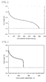
- FIG. 3 shows a relationship between voltage and discharge duration of batteries A1 which showed excellent performance in the discharge condition (d) of the low rate discharge test (ii).
- FIG. 4 shows a relationship between voltage and discharge duration of some of batteries J2 which went dead soon in the same test. Batteries A1 were very long-life batteries as they showed a voltage 1.0 V or more even after 500-hour continuous discharge. In contrast, batteries J2 showed sharp voltage drop to less than 1.0 V after about 300-hour discharge. In the low rate discharge test (ii) under the condition (d), whether the batteries go dead soon or not was judged based on whether or not the batteries were able to discharge continuously for 500 hours or more before the voltage drop to 1.0 V.
- a negative electrode active material t Al: 0.020 wt%, Bi: 0.015 wt%, In: 0.0001 wt%) in an amount of 1.8-times by weight was added and sufficiently mixed to prepare a gelled negative electrode T.
- the positive electrode mixture pellets used in Example 1 were used as the positive electrode.
- separator components five kinds of vinylon-Lyocell composite nonwoven fabric sheets having different thicknesses of (1) 120 ⁇ m, (2) 150 ⁇ m, (3) 180 ⁇ m, (4) 200 ⁇ m and (5) 220 ⁇ m were prepared. After adjustment of size and the like, separators were prepared in accordance with the sheet count and the winding number shown in Table 6 and each of the separators was inserted in the positive electrode mixture pellets together with and an insulating cap. Then, an electrolyte (a 36 wt% potassium hydroxide solution containing 2 wt% of ZnO) was poured and the gelled negative electrode T was introduced to fill space inside the separator. Thus, AA alkaline dry batteries 1-18 of different separator structures were obtained.
- electrolyte a 36 wt% potassium hydroxide solution containing 2 wt% of ZnO
- the volume of the space to be filled with the gelled negative electrode was varied among the batteries.
- the amount of the gelled negative electrode T was adjusted such that the fluid level of the gelled negative electrode became equal (42mm) among the obtained batteries.
- the leakage resistance test (i) and the low rate discharge test (ii) (under four different conditions (a)-(d)) described in Example 1 were carried out.
- the high rate discharge test was replaced with (iv) measurement of CCV (closed circuit voltage) in high rate pulse discharge since the batteries 1-18 containing different amounts of the gelled negative electrode could not be evaluated by the high rate discharge test.
- a minimum voltage of each of the batteries connected to the 1 ⁇ resistance in this period (100 ms) was read and an average among the 3 batteries was obtained as a CCV value.
- Air permeability (Frajour air permeability) of the separator in the stacked state was measured in order to quantitatively estimate the size of gaps among the separator fibers and insulation between the positive and negative electrodes.
- Air permeability of a separator of battery 1 in the "stacked state” the measurement is performed on a stack of two nonwoven fabric sheets (1) having a total thickness of 240 ⁇ m.
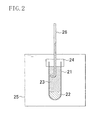
- an air permeability testing machine FX3300 manufactured by TEXTEST was used.
- the Frajour air permeability was measured on the separators of batteries 1-18 in dry state corresponding to the "stacked state” by a method according to JIS L1096.8.27.1.A.
- Table 7 BATTERY No. BATTERY CHARACTERISTIC AIR PERMEABILITY OF SEPARATOR IN STACKED STATE [mL/cm 2 ⁇ sec] (i) RATE OF LEAKAGE [%] (ii) NUMBER OF SHORT-LIFE BATTERY [PIECE] (iv) CCV WHEN CONNECTED TO 1 ⁇ RESISTANCE [V] (a) 75 ⁇ CONTINUOUS (b) 1.2k ⁇ CONTINUOUS (c) 3.9 ⁇ INTERMITTENT (d) 0°C300 ⁇ 1 0 0 0 0 9 1.483 6.5 2 0 0 0 0 7 1.484 6.0 3 0 0 0 0 0 1 1.482 5.2 4 0 0 0 0 0 0 1.483 5.0 5 0 0 0 0 0 0 0 1.482 4.7 6 0 0 0 0 0 1.482 4.3 7 0 0
- a separator made of a larger number of sheets is preferred because it shows higher isolation between the positive and negative electrodes than a separator made of a smaller number of sheets, even if the total separator thickness is the same.
- the assumption is supported by the data of air permeability of the separator measured in the stacked state.
- the air permeability is preferably adjusted to 5 mL/cm 2 ⁇ sec or less.
- batteries 1-16 in which the total separator thickness was 880 ⁇ m or less kept the CCV as high as about 1.48 V, while batteries 17 and 18 in which the total separator thickness was more than 880 ⁇ m showed decrease of the CCV. It is assumed that the total separator thickness of more than 880 ⁇ m excessively increased the resistance between the positive and negative electrodes. Based on the air permeability of the separator measured in the stacked state, it is preferable to set the air permeability of the separator to 0.5 mL/cm 2 ⁇ sec or more to maintain high CCV in the high rate pulse discharge.
- the total thickness of the nonwoven fabric separator is set within the range of 360 ⁇ m to 880 ⁇ m both inclusive. It is more preferable that the air permeability of the separator in the stacked state is set within the range of 0.5 mL/cm 2 ⁇ sec to 5 mL/cm 2 ⁇ sec both inclusive.
- the thus-configured separator makes it possible to restrain the internal short circuit that is likely to occur in the negative electrode using the zinc alloy containing a reduced amount of indium and an increased amount of aluminum in the discharge at low rate and low temperature. Simultaneously, the leakage resistance and high rate discharge characteristic are also enhanced.
- vinylon-Lyocell composite nonwoven fabric was used as the nonwoven fabric.
- other known nonwoven fabrics such as vinylon-rayon composite, vinylon-mercerized pulp composite, nylon and hydrophilic polypropylene nonwoven fabrics are used.
- a negative electrode active material t Al: 0.020 wt%, Bi: 0.015 wt%, In: 0.0001 wt%) in an amount of 1.8-times by weight was added and sufficiently mixed to prepare a gelled negative electrode T.
- the positive electrode mixture pellets used in Example 1 were used as the positive electrode.
- the vinylon-Lyocell composite nonwoven fabric sheets of (1) 120 ⁇ m thick and (3) 180 ⁇ m thick used in Example 2, and cellophane films having different tensile strengths in the lateral direction of (c1) 20N/15mm, (c2) 30N/15mm, (c3) 40N/15mm and (c4) 50N/15mm (manufactured by Futamura Chemical Co., Ltd., about 30 ⁇ m thick) were prepared.
- the tensile strength was measured according to JIS P8113 using a tensile testing machine RTC-1150A manufactured by ORIENTEC Co., Ltd.
- the separator components were combined as described in Table 8 to prepare separators and each of the separators was inserted in the positive electrode mixture pellets together with an insulating cap.
- the cellophane film was stacked on the nonwoven fabric sheet such that the cellophane film comes to the innermost part of the separator (closer to the negative electrode).
- an electrolyte a 36 wt% potassium hydroxide solution containing 2 wt% of ZnO
- the gelled negative electrode T was introduced to fill space inside the separator.
- the volume of the space to be filled with the gelled negative electrode (space inside the cylindrically wound separator) is varied among the batteries.
- the amount of the gelled negative electrode T was adjusted such that the fluid level of the gelled negative electrode became equal (42mm) among the obtained batteries.
- the batteries did not have any problems under the discharge conditions (a)-(c) in the 20°C atmosphere.
- Under the discharge condition (d) of 0°C and 300 ⁇ many of the batteries 21 and 26 went dead soon due to lack of the cellophane film and shortage of the total thickness of the nonwoven fabric sheet.
- the early exhaustion was significantly prevented.
- the cellophane films (c2), (c3) and (c4) having a tensile strength in the lateral direction of 30N/15mm or more, the internal short circuit caused by zinc oxide was completely avoided.
- the cellophane film was stacked on the nonwoven fabric sheet. However, it is assumed that the same effect is obtained even if the cellophane film is bonded to the nonwoven fabric sheet.
- a negative electrode active material t Al: 0.020 wt%, Bi: 0.015 wt%, In: 0.0001 wt%) in an amount of 1.8-times by weight was added and sufficiently mixed to prepare a gelled negative electrode T.
- the positive electrode mixture pellets used in Example 1 were used as the positive electrode.
- the acrylic acid graft-polymerized polyethylene films are hydrophilic microporous films.
- a 35 ⁇ m thick polyethylene film manufactured by Mitsui Chemicals was sulfonated by the following manner to prepare sulfonated polyethylene films having different tensile strengths in the lateral direction of (s1) 10N/15mm, (s2) 20N/15mm, (s3) 30N/15mm and (s4) 35N/15mm.
- the sulfonated polyethylene films are also hydrophilic microporous films.
- the separator components were combined as described in Table 9 to prepare separators and each of the separators was inserted in the positive electrode mixture pellets together with an insulating cap.
- the acrylic acid graft-polymerized polyethylene film or the sulfonated polyethylene film was stacked on the nonwoven fabric sheet such that it comes to the innermost part of the separator (closer to the negative electrode).
- an electrolyte (a 36 wt% potassium hydroxide solution containing 2 wt% of ZnO) was poured and the gelled negative electrode T was introduced to fill space inside the separator.
- AA alkaline dry batteries 31-48 were obtained.
- the volume of the space to be filled with the gelled negative electrode (space inside the cylindrically wound separator) is varied among the batteries.
- the amount of the gelled negative electrode T was adjusted such that the fluid level of the gelled negative electrode became equal (42mm) among the obtained batteries.
- the batteries did not have any problems under the discharge conditions (a)-(c) in the 20°C atmosphere.
- Under the discharge condition (d) of 0°C and 300 ⁇ many of the batteries 31 and 40 in which only the nonwoven fabric sheet was used as the separator went dead soon due to lack of the total thickness of the nonwoven fabric sheet.
- the early exhaustion was significantly restrained.
- the acrylic acid graft-polymerized polyethylene film or the sulfonated polyethylene film was stacked on the nonwoven fabric sheet.
- the same effect is obtained even if the acrylic acid graft-polymerized polyethylene film or the sulfonated polyethylene film is bonded to the nonwoven fabric sheet.
- the acrylic acid graft-polymerized polyethylene film or the sulfonated polyethylene film used herein is replaced with another polyolefin film as long as it has hydrophilicity and micropores.
- a zinc ingot of 99.99 % purity or more was fused at a temperature higher than 500 °C.
- Additive elements were added thereto in the composition ratio shown in Table 10 and the mixture was uniformly fused to obtain a liquid zinc alloy.
- the liquid zinc alloy was powdered by spraying (atomizing) using high pressure gas to obtain zinc alloy powder.
- the obtained zinc alloy powder was sifted to obtain 35-300 mesh powder (the ratio of fine powder of 75 ⁇ m or less: 25 %). In this manner, negative electrode active materials B-a to B-k were obtained.
- each of the negative electrode active materials in an amount of 1.8-times by weight was added and sufficiently mixed to prepare gelled negative electrodes based on different negative electrode active materials.
- the positive electrode mixture pellets used in Example 1 were used as the positive electrode.
- Three vinylon-Lyocell composite nonwoven fabric sheets (thickness of a sheet: 150 ⁇ m) were stacked and wound in one to prepare the separator and the separator was inserted in the positive electrode mixture pellets together with an insulating cap. Then, an electrolyte (a 36 wt% potassium hydroxide solution containing 2 wt% of ZnO) was poured and the gelled negative electrode was introduced to fill space inside the separator. In this manner, AA alkaline dry batteries C-a to C-k were obtained.
- the batteries did not have any problems in the low rate continuous discharge test (ii).
- batteries C-h to C-k in which the indium content in the zinc alloy was 0.015 wt% did not cause leakage irrespective of the bismuth content.
- batteries C-a to C-g in which the indium content in the zinc alloy was 0.0001 wt% batteries C-a and C-b in which the bismuth content was less than 0.005 wt% caused leakage.
- batteries C-g and C-k in which the bismuth content in the zinc alloy was more than 0.03 wt% were likely to deteriorate the characteristics. From these results, the bismuth content in the zinc alloy is preferably set within the range of 0.005-0.03 wt%.
- Electrolytic manganese dioxide HH-PF for alkaline dry battery (MnO 2 purity: 91 wt% or more) manufactured by Tosoh Corporation was added to a 5 wt% sulfuric acid solution at 60 °C to obtain slurry in a concentration of 100g/L. Then, the slurry was stirred at 50°C for an hour and electrolytic manganese dioxide was extracted out by filtration. Then, the extract was washed with water, neutralized with a sodium hydroxide solution, washed again with water and then air-dried at 90 °C for 2 hours. In this process, electrolytic manganese dioxide D-a to D-e different from each other in sodium ion content and sulfate ion content as shown in Table 12 were obtained by varying the conditions of neutralization with the sodium hydroxide solution and water washing.
- Electrolytic manganese dioxide obtained in the foregoing manner and graphite were mixed in the ratio of 94:6 by weight.
- an electrolyte a 36 wt% potassium hydroxide solution containing 2 wt% of ZnO
- Graphite used herein was SP-20 manufactured by Nippon Graphite Industries, ltd.
- a negative electrode active material t Al: 0.020 wt%, Bi: 0.015 wt%, In: 0.0001 wt%) in an amount of 1.8-times by weight was added and sufficiently mixed to prepare a gelled negative electrode T.
- Three vinylon-Lyocell composite nonwoven fabric sheets (thickness of a sheet: 150 ⁇ m) were stacked and wound in one to prepare the separator and the separator was inserted in the positive electrode mixture pellets together with an insulating cap.
- an electrolyte (a 36 wt% potassium hydroxide solution containing 2 wt% of ZnO) was poured and the gelled negative electrode was introduced to fill space inside the separator.
- AA alkaline dry batteries E-a to E-e based on different kinds of electrolytic manganese dioxide were obtained.
- the batteries did not have any problems under the discharge conditions (a)-(c) in the 20°C atmosphere.
- the discharge condition (d) of 0 °C and 300 ⁇ some of batteries E-c in which the sodium ion content in electrolytic manganese dioxide was more than 0.5 wt% and some of batteries E-e in which the sulfate ion content in electrolytic manganese dioxide was more than 1.5 wt% caused internal short circuit.
- a possible cause of this phenomenon is as follows.
- the sodium ion content is high, the sodium ions leach into a KOH-based electrolyte in the battery and the activity of hydroxide ions is decreased. As a result, the solubility of zinc oxide to the electrolyte is reduced. Further, if the sulfate ion content is high, residues of protons mixed as counter ions decrease the alkali concentration of the electrolyte (hydroxide ion concentration). Also in this case, the solubility of zinc oxide to the electrolyte is reduced. In this situation, it is assumed that internal short circuit is likely to occur due to redeposition of zinc oxide in the discharge period at low rate and low temperature.
- sodium ions and sulfate ions contained in the electrolytic manganese dioxide as impurities are preferably controlled to 0.5 wt% or less and 1.5 wt% or less, respectively.
- electrolytic manganese dioxide was subjected to sulfuric acid treatment, neutralization with a sodium hydroxide solution and water washing to adjust the contents of sodium ions and sulfate ions.
- Examples 5 and 6 a stack of three vinylon-Lyocell composite nonwoven fabric sheets (thickness of a sheet: 150 ⁇ m) wound in one was used as the separator in the battery.
- the same effect obtained herein is also obtained even if the separator is made of any kind of nonwoven fabric sheets as long as the total separator thickness is in the range of 360-880 ⁇ m.
- the separator may be made of a stack of a nonwoven fabric sheet of any kind and a cellophane film or a stack of a nonwoven fabric sheet of any kind and a hydrophilic polyolefin film.
- the particle size of the negative electrode active material was controlled to 35-300 mesh (the ratio of fine powder of 75 ⁇ m or less: 25 %).
- the present invention is not limited thereto.
- the present invention can be applied to alkaline dry batteries using zinc alloy powder of any particle size as the negative electrode active material.
- Examples 1 to 6 AA alkaline dry batteries were prepared for evaluation.
- the present invention offers the same effect even if the invention is applied to alkaline dry batteries of other sizes. Further, the same effect is also expected even if the invention is applied to alkaline dry batteries using a mixture of manganese dioxide and nickel oxyhydroxide as the positive electrode active material (nickel-based dry batteries).
- the alkaline dry battery according to the present invention has excellent resistance to leakage and favorable discharge characteristics and does not cause internal short circuit even in a discharge period at low rate and low temperature. Therefore, the alkaline dry battery of the present invention delivers its performance with stability even when it is applied to various electronic devices and general purpose devices, as well as a headlight which may be continuously used outside in wintertime and a battery-powered refrigerant deodorant.
Landscapes
- Chemical & Material Sciences (AREA)
- Chemical Kinetics & Catalysis (AREA)
- Electrochemistry (AREA)
- General Chemical & Material Sciences (AREA)
- Engineering & Computer Science (AREA)
- Manufacturing & Machinery (AREA)
- Battery Electrode And Active Subsutance (AREA)
- Primary Cells (AREA)
- Powder Metallurgy (AREA)
- Cell Separators (AREA)
Applications Claiming Priority (1)
| Application Number | Priority Date | Filing Date | Title |
|---|---|---|---|
| JP2007006034A JP4199811B2 (ja) | 2007-01-15 | 2007-01-15 | アルカリ乾電池 |
Publications (2)
| Publication Number | Publication Date |
|---|---|
| EP1959023A1 true EP1959023A1 (fr) | 2008-08-20 |
| EP1959023B1 EP1959023B1 (fr) | 2010-05-26 |
Family
ID=39473788
Family Applications (1)
| Application Number | Title | Priority Date | Filing Date |
|---|---|---|---|
| EP08150119A Not-in-force EP1959023B1 (fr) | 2007-01-15 | 2008-01-09 | Batterie sèche alcaline |
Country Status (4)
| Country | Link |
|---|---|
| US (1) | US20080171266A1 (fr) |
| EP (1) | EP1959023B1 (fr) |
| JP (1) | JP4199811B2 (fr) |
| CN (1) | CN101227001B (fr) |
Cited By (3)
| Publication number | Priority date | Publication date | Assignee | Title |
|---|---|---|---|---|
| US8735001B2 (en) | 2011-04-08 | 2014-05-27 | Empire Technology Development Llc | Gel formed battery |
| US8828581B2 (en) | 2011-04-08 | 2014-09-09 | Empire Technology Development Llc | Liquid battery formed from encapsulated components |
| US11898283B2 (en) * | 2018-01-31 | 2024-02-13 | Reifenhaeuser Gmbh & Co. Kg Maschinenfabrik | Method of making a spunbond nonwoven laminate |
Families Citing this family (24)
| Publication number | Priority date | Publication date | Assignee | Title |
|---|---|---|---|---|
| JP5278332B2 (ja) * | 2008-07-09 | 2013-09-04 | パナソニック株式会社 | リチウム一次電池用電解二酸化マンガンとその製造方法およびそれを用いたリチウム一次電池 |
| JP2012501040A (ja) * | 2008-08-29 | 2012-01-12 | パナソニック株式会社 | マンガン乾電池 |
| JP5434412B2 (ja) * | 2008-09-17 | 2014-03-05 | 株式会社リコー | 静電潜像現像用キャリア、二成分現像剤、補給用現像剤、及びプロセスカートリッジ、並びに画像形成方法 |
| US20110223477A1 (en) * | 2010-03-12 | 2011-09-15 | Nelson Jennifer A | Alkaline battery including lambda-manganese dioxide and method of making thereof |
| US8303840B2 (en) * | 2010-03-12 | 2012-11-06 | The Gillette Company | Acid-treated manganese dioxide and methods of making thereof |
| US20110219607A1 (en) * | 2010-03-12 | 2011-09-15 | Nanjundaswamy Kirakodu S | Cathode active materials and method of making thereof |
| US8298706B2 (en) | 2010-03-12 | 2012-10-30 | The Gillette Company | Primary alkaline battery |
| WO2012044283A1 (fr) * | 2010-09-28 | 2012-04-05 | Empire Technology Development Llc | Tubes de cathode à air pour accumulateurs métal-air rechargeables |
| US8722228B2 (en) | 2011-04-08 | 2014-05-13 | Empire Technology Development Llc | Moisture activated battery |
| WO2012138351A1 (fr) * | 2011-04-08 | 2012-10-11 | Empire Technology Development Llc | Accumulateur formé par un gel |
| JP5844166B2 (ja) | 2012-01-31 | 2016-01-13 | ニッポン高度紙工業株式会社 | アルカリ電池用セパレータ及びアルカリ電池 |
| US9570741B2 (en) | 2012-03-21 | 2017-02-14 | Duracell U.S. Operations, Inc. | Metal-doped nickel oxide active materials |
| US9028564B2 (en) | 2012-03-21 | 2015-05-12 | The Gillette Company | Methods of making metal-doped nickel oxide active materials |
| US8703336B2 (en) | 2012-03-21 | 2014-04-22 | The Gillette Company | Metal-doped nickel oxide active materials |
| US9793542B2 (en) | 2014-03-28 | 2017-10-17 | Duracell U.S. Operations, Inc. | Beta-delithiated layered nickel oxide electrochemically active cathode material and a battery including said material |
| EP3425698B9 (fr) | 2016-02-29 | 2024-02-14 | Nippon Kodoshi Corporation | Séparateur de batterie alcaline et batterie alcaline |
| CN108886114A (zh) * | 2016-05-27 | 2018-11-23 | 松下知识产权经营株式会社 | 密闭型电池以及电池壳体 |
| CN106684318B (zh) * | 2017-01-23 | 2019-04-05 | 浙江长虹飞狮电器工业有限公司 | 一种碱性电池负极制备方法 |
| WO2018208860A1 (fr) | 2017-05-09 | 2018-11-15 | Duracell U.S. Operations, Inc. | Batterie incluant un matériau de cathode électrochimiquement actif à l'oxyde de nickel stratifié bêta-délithié |
| CN110676416A (zh) * | 2019-11-08 | 2020-01-10 | 温岭市聚智高分子材料有限公司 | 碱性电池隔膜及其制备方法 |
| CN112103560B (zh) * | 2020-09-16 | 2021-11-26 | 武汉大学 | 一种基于吸湿性水凝胶的电池及其制备方法 |
| US20250029981A1 (en) * | 2021-10-06 | 2025-01-23 | Panasonic Intellectual Property Management Co., Ltd. | Alkaline battery |
| CN120604363A (zh) * | 2023-02-14 | 2025-09-05 | 松下知识产权经营株式会社 | 碱性干电池 |
| CN120999199A (zh) * | 2025-10-24 | 2025-11-21 | 东莞胜力电池实业有限公司 | 一种脉冲无汞锌空气纽扣电池及其制备方法 |
Citations (8)
| Publication number | Priority date | Publication date | Assignee | Title |
|---|---|---|---|---|
| JPS6177259A (ja) * | 1984-09-21 | 1986-04-19 | Mitsui Mining & Smelting Co Ltd | 亜鉛アルカリ電池 |
| US4735876A (en) * | 1984-02-20 | 1988-04-05 | Matsushita Electric Industrial Co., Ltd. | Zinc-alkaline battery |
| JP2001155707A (ja) | 1999-11-24 | 2001-06-08 | Toshiba Battery Co Ltd | アルカリ電池 |
| JP2002511638A (ja) | 1998-04-15 | 2002-04-16 | デュラセル インコーポレイテッド | バッテリセパレータ |
| JP3310935B2 (ja) | 1998-08-18 | 2002-08-05 | ニッポン高度紙工業株式会社 | アルカリ電池用セパレータ紙 |
| JP2002270164A (ja) * | 2001-03-09 | 2002-09-20 | Mitsui Mining & Smelting Co Ltd | 亜鉛合金粉及びこれを用いたアルカリ電池 |
| JP2004164863A (ja) | 2002-11-08 | 2004-06-10 | Toshiba Battery Co Ltd | 密閉型ニッケル亜鉛一次電池 |
| US20060005663A1 (en) * | 2004-06-28 | 2006-01-12 | Danan Fan | Alkaline electrochemical cell with a blended zinc powder |
Family Cites Families (10)
| Publication number | Priority date | Publication date | Assignee | Title |
|---|---|---|---|---|
| US5626988A (en) * | 1994-05-06 | 1997-05-06 | Battery Technologies Inc. | Sealed rechargeable cells containing mercury-free zinc anodes, and a method of manufacture |
| US6270833B1 (en) * | 1998-05-28 | 2001-08-07 | Fdk Corporation | Separator for an alkaline cell and a method of producing the separator |
| US6495292B1 (en) * | 2000-04-26 | 2002-12-17 | William W. Yen | Wettable nonwoven battery separator |
| US6585881B2 (en) * | 2001-02-20 | 2003-07-01 | The Gillette Company | Process for manufacture and improved manganese dioxide for electrochemical cells |
| ES2282414T3 (es) * | 2001-05-10 | 2007-10-16 | Lenzing Aktiengesellschaft | Separadores de bateria. |
| DE10143898B4 (de) * | 2001-09-07 | 2005-07-14 | Carl Freudenberg Kg | Alkalische Zelle oder Batterie |
| US6921606B2 (en) * | 2002-04-16 | 2005-07-26 | Gore Enterprise Holdings, Inc. | Composite films for electrochemical devices |
| GR20030100208A (el) * | 2002-05-15 | 2004-02-02 | Mitsui Mining & Smelting Co., Ltd. | Ενεργο υλικο καθοδου συσσωρευτη, μεθοδος παραγωγης του και μπαταρια που το χρησιμοποιει |
| JP4736345B2 (ja) * | 2004-04-23 | 2011-07-27 | パナソニック株式会社 | アルカリ電池 |
| JP4936502B2 (ja) * | 2005-06-24 | 2012-05-23 | 日立マクセルエナジー株式会社 | 円筒形アルカリ電池およびその製造方法 |
-
2007
- 2007-01-15 JP JP2007006034A patent/JP4199811B2/ja not_active Expired - Fee Related
-
2008
- 2008-01-09 EP EP08150119A patent/EP1959023B1/fr not_active Not-in-force
- 2008-01-09 US US11/971,495 patent/US20080171266A1/en not_active Abandoned
- 2008-01-15 CN CN2008100021271A patent/CN101227001B/zh not_active Expired - Fee Related
Patent Citations (9)
| Publication number | Priority date | Publication date | Assignee | Title |
|---|---|---|---|---|
| US4735876A (en) * | 1984-02-20 | 1988-04-05 | Matsushita Electric Industrial Co., Ltd. | Zinc-alkaline battery |
| JPS6177259A (ja) * | 1984-09-21 | 1986-04-19 | Mitsui Mining & Smelting Co Ltd | 亜鉛アルカリ電池 |
| JPH0371737B2 (fr) | 1984-09-21 | 1991-11-14 | Mitsui Kinzoku Kogyo Kk | |
| JP2002511638A (ja) | 1998-04-15 | 2002-04-16 | デュラセル インコーポレイテッド | バッテリセパレータ |
| JP3310935B2 (ja) | 1998-08-18 | 2002-08-05 | ニッポン高度紙工業株式会社 | アルカリ電池用セパレータ紙 |
| JP2001155707A (ja) | 1999-11-24 | 2001-06-08 | Toshiba Battery Co Ltd | アルカリ電池 |
| JP2002270164A (ja) * | 2001-03-09 | 2002-09-20 | Mitsui Mining & Smelting Co Ltd | 亜鉛合金粉及びこれを用いたアルカリ電池 |
| JP2004164863A (ja) | 2002-11-08 | 2004-06-10 | Toshiba Battery Co Ltd | 密閉型ニッケル亜鉛一次電池 |
| US20060005663A1 (en) * | 2004-06-28 | 2006-01-12 | Danan Fan | Alkaline electrochemical cell with a blended zinc powder |
Cited By (3)
| Publication number | Priority date | Publication date | Assignee | Title |
|---|---|---|---|---|
| US8735001B2 (en) | 2011-04-08 | 2014-05-27 | Empire Technology Development Llc | Gel formed battery |
| US8828581B2 (en) | 2011-04-08 | 2014-09-09 | Empire Technology Development Llc | Liquid battery formed from encapsulated components |
| US11898283B2 (en) * | 2018-01-31 | 2024-02-13 | Reifenhaeuser Gmbh & Co. Kg Maschinenfabrik | Method of making a spunbond nonwoven laminate |
Also Published As
| Publication number | Publication date |
|---|---|
| CN101227001A (zh) | 2008-07-23 |
| CN101227001B (zh) | 2011-09-21 |
| JP4199811B2 (ja) | 2008-12-24 |
| US20080171266A1 (en) | 2008-07-17 |
| EP1959023B1 (fr) | 2010-05-26 |
| JP2008171767A (ja) | 2008-07-24 |
Similar Documents
| Publication | Publication Date | Title |
|---|---|---|
| EP1959023B1 (fr) | Batterie sèche alcaline | |
| EP0758491B1 (fr) | Piles etanches rechargeables a anodes de zinc sans mercure et leur procede de fabrication | |
| US7169508B2 (en) | Method of manufacturing anode compositions for use in rechargeable electrochemical cells | |
| EP2489086B1 (fr) | Cellule de zinc-nickel cylindrique avec corps de cylindre positif | |
| JP4102184B2 (ja) | アルミニウム負極電池 | |
| JP5240897B2 (ja) | アルカリ電池 | |
| US20060046135A1 (en) | Alkaline battery with MnO2/NiOOH active material | |
| CN101473468A (zh) | 碱性电化学电池 | |
| US20090263710A1 (en) | Aa alkaline battery | |
| JP5419256B2 (ja) | アルカリ電池 | |
| CN100585925C (zh) | 钮扣碱性电池及其制造方法 | |
| JP2010524173A (ja) | 小型セルのための銀含有層を有する多層正極構造 | |
| JP5348717B2 (ja) | アルカリ電池 | |
| JP5455182B2 (ja) | アルカリ電池 | |
| JP2009043417A (ja) | 筒形アルカリ電池 | |
| US20090246071A1 (en) | Hydrogen storage alloy | |
| EP2337129B1 (fr) | Batterie alcaline | |
| JP5981807B2 (ja) | アルカリ電池 | |
| JP7611850B2 (ja) | アルカリ電池用正極、並びに、アルカリ電池およびその製造方法 | |
| CN116349061A (zh) | 负极及锌二次电池 | |
| JP2004139909A (ja) | 密閉型ニッケル亜鉛一次電池 | |
| JP7748361B2 (ja) | 扁平形電池およびその製造方法 | |
| EP1668721B1 (fr) | Pile alcaline seche | |
| US9748560B2 (en) | Negative electrode for alkaline secondary battery, outer case for alkaline secondary battery and alkaline secondary battery |
Legal Events
| Date | Code | Title | Description |
|---|---|---|---|
| PUAI | Public reference made under article 153(3) epc to a published international application that has entered the european phase |
Free format text: ORIGINAL CODE: 0009012 |
|
| AK | Designated contracting states |
Kind code of ref document: A1 Designated state(s): AT BE BG CH CY CZ DE DK EE ES FI FR GB GR HR HU IE IS IT LI LT LU LV MC MT NL NO PL PT RO SE SI SK TR |
|
| AX | Request for extension of the european patent |
Extension state: AL BA MK RS |
|
| RAP1 | Party data changed (applicant data changed or rights of an application transferred) |
Owner name: PANASONIC CORPORATION |
|
| 17P | Request for examination filed |
Effective date: 20090109 |
|
| 17Q | First examination report despatched |
Effective date: 20090224 |
|
| AKX | Designation fees paid |
Designated state(s): BE CH LI |
|
| REG | Reference to a national code |
Ref country code: DE Ref legal event code: 8566 |
|
| GRAP | Despatch of communication of intention to grant a patent |
Free format text: ORIGINAL CODE: EPIDOSNIGR1 |
|
| GRAS | Grant fee paid |
Free format text: ORIGINAL CODE: EPIDOSNIGR3 |
|
| GRAA | (expected) grant |
Free format text: ORIGINAL CODE: 0009210 |
|
| AK | Designated contracting states |
Kind code of ref document: B1 Designated state(s): BE CH LI |
|
| REG | Reference to a national code |
Ref country code: CH Ref legal event code: EP |
|
| REG | Reference to a national code |
Ref country code: CH Ref legal event code: NV Representative=s name: NOVAGRAAF INTERNATIONAL SA |
|
| PLBE | No opposition filed within time limit |
Free format text: ORIGINAL CODE: 0009261 |
|
| STAA | Information on the status of an ep patent application or granted ep patent |
Free format text: STATUS: NO OPPOSITION FILED WITHIN TIME LIMIT |
|
| 26N | No opposition filed |
Effective date: 20110301 |
|
| REG | Reference to a national code |
Ref country code: CH Ref legal event code: PFA Owner name: PANASONIC CORPORATION Free format text: PANASONIC CORPORATION#1006, OAZA KADOMA#KADOMA-SHI OSAKA 571-8501 (JP) -TRANSFER TO- PANASONIC CORPORATION#1006, OAZA KADOMA#KADOMA-SHI OSAKA 571-8501 (JP) |
|
| PGFP | Annual fee paid to national office [announced via postgrant information from national office to epo] |
Ref country code: CH Payment date: 20120112 Year of fee payment: 5 |
|
| REG | Reference to a national code |
Ref country code: CH Ref legal event code: PL |
|
| PG25 | Lapsed in a contracting state [announced via postgrant information from national office to epo] |
Ref country code: CH Free format text: LAPSE BECAUSE OF NON-PAYMENT OF DUE FEES Effective date: 20130131 Ref country code: LI Free format text: LAPSE BECAUSE OF NON-PAYMENT OF DUE FEES Effective date: 20130131 |
|
| PGFP | Annual fee paid to national office [announced via postgrant information from national office to epo] |
Ref country code: BE Payment date: 20171213 Year of fee payment: 11 |
|
| REG | Reference to a national code |
Ref country code: BE Ref legal event code: MM Effective date: 20190131 |
|
| PG25 | Lapsed in a contracting state [announced via postgrant information from national office to epo] |
Ref country code: BE Free format text: LAPSE BECAUSE OF NON-PAYMENT OF DUE FEES Effective date: 20190131 |