EP1959103A2 - Prallgekühltes Trägergehäuse mit Thermoelement, Verfahren zur Kühlung - Google Patents
Prallgekühltes Trägergehäuse mit Thermoelement, Verfahren zur Kühlung Download PDFInfo
- Publication number
- EP1959103A2 EP1959103A2 EP08101505A EP08101505A EP1959103A2 EP 1959103 A2 EP1959103 A2 EP 1959103A2 EP 08101505 A EP08101505 A EP 08101505A EP 08101505 A EP08101505 A EP 08101505A EP 1959103 A2 EP1959103 A2 EP 1959103A2
- Authority
- EP
- European Patent Office
- Prior art keywords
- casing
- impingement
- impingement cooling
- manifold
- turbine
- Prior art date
- Legal status (The legal status is an assumption and is not a legal conclusion. Google has not performed a legal analysis and makes no representation as to the accuracy of the status listed.)
- Withdrawn
Links
- 238000001816 cooling Methods 0.000 title claims abstract description 58
- 238000000034 method Methods 0.000 claims description 8
- 238000007664 blowing Methods 0.000 claims description 3
- 238000006073 displacement reaction Methods 0.000 claims description 3
- 239000003570 air Substances 0.000 description 15
- 238000012986 modification Methods 0.000 description 3
- 230000004048 modification Effects 0.000 description 3
- OKTJSMMVPCPJKN-UHFFFAOYSA-N Carbon Chemical compound [C] OKTJSMMVPCPJKN-UHFFFAOYSA-N 0.000 description 2
- 230000008901 benefit Effects 0.000 description 2
- 229910002804 graphite Inorganic materials 0.000 description 2
- 239000010439 graphite Substances 0.000 description 2
- 239000002184 metal Substances 0.000 description 2
- 239000012080 ambient air Substances 0.000 description 1
- 230000008859 change Effects 0.000 description 1
- 239000002826 coolant Substances 0.000 description 1
- 230000001419 dependent effect Effects 0.000 description 1
- 230000001627 detrimental effect Effects 0.000 description 1
- 238000000605 extraction Methods 0.000 description 1
- 238000012163 sequencing technique Methods 0.000 description 1
- 230000007704 transition Effects 0.000 description 1
Images


Classifications
-
- F—MECHANICAL ENGINEERING; LIGHTING; HEATING; WEAPONS; BLASTING
- F01—MACHINES OR ENGINES IN GENERAL; ENGINE PLANTS IN GENERAL; STEAM ENGINES
- F01D—NON-POSITIVE DISPLACEMENT MACHINES OR ENGINES, e.g. STEAM TURBINES
- F01D25/00—Component parts, details, or accessories, not provided for in, or of interest apart from, other groups
- F01D25/08—Cooling; Heating; Heat-insulation
- F01D25/12—Cooling
-
- F—MECHANICAL ENGINEERING; LIGHTING; HEATING; WEAPONS; BLASTING
- F01—MACHINES OR ENGINES IN GENERAL; ENGINE PLANTS IN GENERAL; STEAM ENGINES
- F01D—NON-POSITIVE DISPLACEMENT MACHINES OR ENGINES, e.g. STEAM TURBINES
- F01D11/00—Preventing or minimising internal leakage of working-fluid, e.g. between stages
- F01D11/08—Preventing or minimising internal leakage of working-fluid, e.g. between stages for sealing space between rotor blade tips and stator
- F01D11/14—Adjusting or regulating tip-clearance, i.e. distance between rotor-blade tips and stator casing
- F01D11/20—Actively adjusting tip-clearance
- F01D11/24—Actively adjusting tip-clearance by selectively cooling-heating stator or rotor components
-
- F—MECHANICAL ENGINEERING; LIGHTING; HEATING; WEAPONS; BLASTING
- F05—INDEXING SCHEMES RELATING TO ENGINES OR PUMPS IN VARIOUS SUBCLASSES OF CLASSES F01-F04
- F05D—INDEXING SCHEME FOR ASPECTS RELATING TO NON-POSITIVE-DISPLACEMENT MACHINES OR ENGINES, GAS-TURBINES OR JET-PROPULSION PLANTS
- F05D2260/00—Function
- F05D2260/20—Heat transfer, e.g. cooling
- F05D2260/201—Heat transfer, e.g. cooling by impingement of a fluid
-
- Y—GENERAL TAGGING OF NEW TECHNOLOGICAL DEVELOPMENTS; GENERAL TAGGING OF CROSS-SECTIONAL TECHNOLOGIES SPANNING OVER SEVERAL SECTIONS OF THE IPC; TECHNICAL SUBJECTS COVERED BY FORMER USPC CROSS-REFERENCE ART COLLECTIONS [XRACs] AND DIGESTS
- Y02—TECHNOLOGIES OR APPLICATIONS FOR MITIGATION OR ADAPTATION AGAINST CLIMATE CHANGE
- Y02T—CLIMATE CHANGE MITIGATION TECHNOLOGIES RELATED TO TRANSPORTATION
- Y02T50/00—Aeronautics or air transport
- Y02T50/60—Efficient propulsion technologies, e.g. for aircraft
Definitions
- Air impingement cooling has been used to manage the casing temperature of small gas turbines and to reduce and maintain the clearances between rotating blades and accompanying interior casing surfaces.
- One problem for air impingement cooling systems on heavy-duty gas turbines is the ability to achieve a uniform heat transfer coefficient across large non-uniform non-standard casing surfaces.
- small impingement holes and short nozzle to surface distances are normally applied. These factors produce the required higher heat transfer coefficients on the casing.
- One detrimental impact of applying small of impingement cooling holes is the need for operating with high differential pressure drop across the holes. This results in the requirement for undesirable high cooling air supply pressures which negatively impacts net efficiency.
- Impingement cooling has been applied to aircraft engines as a method of turbine clearance control.
- the impingement systems used on aircraft engines cannot be used in heavy-duty turbine applications.
- the systems applied to aircraft engines utilize air extracted from the compressor as the cooling medium. It is not feasible to use compressor extraction air on heavy-duty gas turbines because the design heat transfer coefficients require cooler air temperatures.
- Heavy-duty gas turbines have a significantly larger, non-uniform casing surface that requires an intricate manifold design as compared to aircraft engines. Also, the casing thickness and casing thickness variations are considerably greater on heavy-duty gas turbines.
- An impingement cooling system has been recently developed that can provide clearance control on heavy-duty gas turbines. This system properly delivers the required heat transfer coefficient to the targeted casing surface, and properly controls the flow of air to the casing.
- This invention relates to mounting details and methods of the impingement cooling manifolds of the above-mentioned recently developed impingement cooling system. More specifically, the invention provides manifold mounts that both support the manifolds off the turbine casing and function as wells for multiple embedded casing thermocouples.
- the invention may be embodied an impingement cooling system for heavy duty turbines comprising: a impingement cooling manifold affixed to a casing of the heavy-duty turbine, wherein the impingement cooling manifold comprises a plurality of impingement holes in the surface of the impingement cooling manifold; a blower that provides air flow across the plurality of impingement holes of the impingement cooling manifold to cool the casing of the heavy-duty turbine to control a clearance between a tip of a turbine blade and a shroud of the heavy-duty turbine; and at least one support for supporting the impingement cooling manifold spaced from said casing, said support having a bore defined therethrough for receiving a casing thermocouple.
- the invention may also be embodied in a method of cooling a heavy duty turbine casing comprising: affixing at least one impingement cooling manifold comprising a plurality of impingement holes to the casing with at least one support for supporting the impingement cooling manifold spaced from said casing, said support having a bore defined therethrough for receiving a casing thermocouple; and blowing air into the manifold and through the impingement holes to cool the casing and to control a clearance between at least one blade tip and at least one shroud located within the casing.
- FIGURE 1 illustrates an example embodiment of a heavy-duty turbine 110.
- the heavy-duty turbine engine includes a compressor section 112, combustor section 114, and a turbine section 116.
- the turbine 110 also includes a compressor casing 118 and a turbine casing 120.
- the turbine and compressor casings 118, 120 enclose major parts of the heavy-duty turbine.
- the turbine section 116 includes a shaft and a plurality of sets of rotating and stationary turbine blades.
- the turbine casing 120 may include a shroud 126 affixed to the interior surface of the casing 120.
- the shroud 126 may be positioned proximate to the tips of the rotating turbine blades 122 to minimize air leakage past the blade tips 123.
- the distance between the blade tip 123 and the shroud 126 is referred to as the clearance 128. It is noted that the clearances 128 of each turbine stage are not consistent due to the different thermal growth characteristics of the blades and casing.
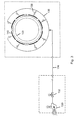
- FIGURE 2 schematically illustrates the clearance 128 between the turbine blade tips 123 and the shroud 126 in the turbine casing 120. Due to the different thermal growth characteristics of the turbine blade tip 123 and turbine casing 120, clearances 128 significantly change as the turbine transitions through transients from ignition to a base-load steady state condition.
- a clearance control system including its operating sequence may be implemented to address the specific clearance characteristics during all operating conditions. Incorrect design and/or sequencing of the control system may lead to excessive rubbing of the turbine blade tips 123 with the casing shrouds 126, which can result in increased clearances and reduced performance.
- an impingement air-cooling system may be used to reduce and maintain the clearances between the turbine shroud 126 and the accompanying blade tip 123.
- the impingement air-cooling system may include a blower 130, a flow control damper 132, interconnect piping 134, a distribution header 136, flow metering valves or orifices 138 and a series impingement cooling manifolds 140.
- a plurality of impingement manifolds 140 are affixed about the circumference of the turbine casing 120.
- the impingement cooling blower 130 draws in ambient air and blows the air through the flow control damper 132, interconnect piping 134, distribution header 136, flow metering valves or orifices 138 and into the impingement cooling manifolds 140.
- the blower 130 may be any blowing device including a fan or a jet.
- the impingement cooling manifold 140 insures a uniform heat transfer coefficient is delivered to the turbine casing 120. It should be appreciated that the impingement air-cooling system is not limited to the components disclosed herein but may include any components that enable air to pass along the impingement cooling manifolds.
- the impingement cooling manifolds 140 may be designed to the contours of the target area of the turbine casing 120.
- Each impingement cooling manifold 140 may include an upper plate 142 with feed pipe 144, a lower plate 146 with multiple impingement holes 148, side pieces, leveling legs 150 and hold-down supports 152 (described more fully below).
- the impingement holes 148 permit the air to flow from the impingement cooling manifold to the turbine casing to selectively cool the turbine casing.
- the impingement holes 148 are positioned in an array.
- the impingement holes 148 may be spaced in the range from 1.25 to 2.5 inches.
- the individual impingement holes 148 may be sized between 0.12 and 0.2 inches.
- the varying hole sizes and spacing are required to compensate for the non-uniformity of the turbine casing geometry.
- the size and positioning of the impingement holes 148 on the lower plate 146 produces a uniform heat transfer coefficient across the casing targeted by the impingement air-cooling system.
- the impingement holes are not limited to these sizes or spacings.
- the distance between the upper 142 and lower plates 146 may also be dimensioned to minimize internal pressure variations, which results in uniform cooling hole pressure ratios.
- the gap distance between impingement cooling manifold lower plates 146 and the turbine casing 120 affects the heat transfer coefficient. Too large of a gap can result in a non-optimum heat transfer coefficient. Too small of a gap can result in both non-optimum and a non-uniform heat transfer coefficient.
- a gap of between 0.5 and 1.0 inch provides a suitable heat transfer coefficient. However, the gap in not limited to this range and may be any distance that provides a suitable heat transfer coefficient.
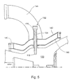
- FIGURE 6 illustrates in greater detail hold down support 152, which in example embodiments of the invention both supports the manifold 140 at a predetermined distance from the surface of the turbine casing 120 and functions as a well for a casing thermocouple to monitor the temperature of the casing.
- the support/thermocouple housing 152 is comprised of a bushing 154 having a threaded exterior surface 156 inserted through race track holes 158,160 defined in upper plate 142 and lower plate 146, respectively.
- a threaded sleeve 162 is engaged with the bushing at the interface with lower plate 146. More particularly, the threaded sleeve is welded to the lower plate and has a threaded interior surface for threadably engaging the bushing. Rotating the bushing relative to the threaded sleeve advances the bushing distal end toward the casing, until it is abutted thereagainst as shown in FIGURES 5 and 6 .
- an assembly comprised of a graphite gasket 164, sheet metal washer 166 and custom nut 168 are respectively disposed about the exterior of the bushing 154.
- the graphite gasket 164 and the sheet metal washer 166 are each about 1/16 inch thick.
- the custom nut 168 threadably engages the bushing 154 to bear down on the upper plate 142.
- a mount bolt 170 Inserted within the bushing is a mount bolt 170.
- a mount bolt 170 has a threaded distal end 172 for threadably engaging a threaded counter bore 176 in the turbine casing 120 and a flange 174 at the proximal end thereof for engaging the proximal end of the bushing.
- the thermocouple is threaded to the proximal end of the mounting bolt and includes a thin wire (not shown) disposed through the bore of the mounting bolt and terminating in the counter bore defined in the casing.
- the sensor (not shown) at the end of the thermocouple wire makes contact with the casing in the counter bore, below the threaded engagement of the mounting bolt with the casing.
- the hole 158 defined in the upper plate 142 is dimensioned to allow a limited amount of lateral play of the manifold upper plate with respect to the bushing 154 right and left while lift of the manifold with respect to the bushing is precluded by the custom nut 168.
- the mounting bolt 170 inserted through the bore of the bushing 154 is threadably engaged with the casing 120 and has upper flange 174 for limiting displacement of the bushing away from the casing so that the mounting bolt determines the position of the bushing 154 with respect to the casing 120 and rotating the bushing 154 determines the position of the manifold 140 with respect to the casing 120.
- two supports/thermocouple housings are provided for supporting the (each) manifold off the casing.
- one of the integrated supports is engaged with a threaded sleeve as described above with reference to FIGURE 6 , whereas the other support is inserted through the lower plate in the absence of the threaded sleeve. Instead a slot is defined therefor in the lower plate, to allow thermal growth of the manifold.
- the two supports respectively provide fixed attachment and attachment with play with respect to the lower plate.
- the multiple impingement cooling manifolds 140 are affixed to the casing 120 of the turbine directly above the target cooling area.
- the impingement cooling manifolds 140 are positioned such that there is ample spacing between their edges and any protrusions off of the casing. This provides a free path for the air passing through the impingement holes 148 to exhaust from under the impingement cooling manifold 140 to the environment.
- the spacing between two adjacent impingement cooling manifolds may be between 1 to 30 inches and is dependent on casing protrusions and flanged joints. The spacings are not limited to these dimensions and may be spaced at any suitable distance.
- the impingement cooling manifolds 140 also may provide impingement cooling to any of the axial flanges, including the horizontal split joint.
Landscapes
- Engineering & Computer Science (AREA)
- Mechanical Engineering (AREA)
- General Engineering & Computer Science (AREA)
- Turbine Rotor Nozzle Sealing (AREA)
Applications Claiming Priority (1)
| Application Number | Priority Date | Filing Date | Title |
|---|---|---|---|
| US11/705,496 US7914254B2 (en) | 2007-02-13 | 2007-02-13 | Integrated support/thermocouple housing for impingement cooling manifolds and cooling method |
Publications (1)
| Publication Number | Publication Date |
|---|---|
| EP1959103A2 true EP1959103A2 (de) | 2008-08-20 |
Family
ID=39144437
Family Applications (1)
| Application Number | Title | Priority Date | Filing Date |
|---|---|---|---|
| EP08101505A Withdrawn EP1959103A2 (de) | 2007-02-13 | 2008-02-12 | Prallgekühltes Trägergehäuse mit Thermoelement, Verfahren zur Kühlung |
Country Status (3)
| Country | Link |
|---|---|
| US (1) | US7914254B2 (de) |
| EP (1) | EP1959103A2 (de) |
| JP (1) | JP2008196490A (de) |
Cited By (1)
| Publication number | Priority date | Publication date | Assignee | Title |
|---|---|---|---|---|
| DE102009044407B4 (de) * | 2008-11-10 | 2017-11-09 | General Electric Co. | Von Außen verstellbare Befestigung eines Aufprallkühlverteilers und Thermoelement-Gehäuse |
Families Citing this family (14)
| Publication number | Priority date | Publication date | Assignee | Title |
|---|---|---|---|---|
| US8801370B2 (en) * | 2006-10-12 | 2014-08-12 | General Electric Company | Turbine case impingement cooling for heavy duty gas turbines |
| US7837429B2 (en) * | 2006-10-12 | 2010-11-23 | General Electric Company | Predictive model based control system for heavy duty gas turbines |
| US20120023967A1 (en) * | 2010-07-30 | 2012-02-02 | Dede Brian C | Auxiliary power unit with hot section fire enclosure arrangement |
| GB201112163D0 (en) * | 2011-07-15 | 2011-08-31 | Rolls Royce Plc | Tip clearance control for turbine blades |
| EP2574732A2 (de) * | 2011-09-29 | 2013-04-03 | Hitachi Ltd. | Gasturbine |
| WO2013141938A1 (en) | 2011-12-30 | 2013-09-26 | Rolls-Royce North American Technologies, Inc. | Gas turbine engine tip clearance control |
| US9422824B2 (en) | 2012-10-18 | 2016-08-23 | General Electric Company | Gas turbine thermal control and related method |
| US9238971B2 (en) | 2012-10-18 | 2016-01-19 | General Electric Company | Gas turbine casing thermal control device |
| WO2016025054A2 (en) * | 2014-05-29 | 2016-02-18 | General Electric Company | Engine components with cooling features |
| US10428676B2 (en) * | 2017-06-13 | 2019-10-01 | Rolls-Royce Corporation | Tip clearance control with variable speed blower |
| FR3073007B1 (fr) * | 2017-10-27 | 2019-09-27 | Safran Aircraft Engines | Dispositif de maintien d'un tube de refroidissement pour carter de turbomachine |
| KR102593506B1 (ko) * | 2018-09-11 | 2023-10-24 | 한화에어로스페이스 주식회사 | 가스 터빈 장치의 케이스 구조체 |
| JP6508499B1 (ja) * | 2018-10-18 | 2019-05-08 | 三菱日立パワーシステムズ株式会社 | ガスタービン静翼、これを備えているガスタービン、及びガスタービン静翼の製造方法 |
| US11255214B2 (en) * | 2019-11-04 | 2022-02-22 | Raytheon Technologies Corporation | Negative thermal expansion compressor case for improved tip clearance |
Family Cites Families (20)
| Publication number | Priority date | Publication date | Assignee | Title |
|---|---|---|---|---|
| US2650753A (en) * | 1947-06-11 | 1953-09-01 | Gen Electric | Turbomachine stator casing |
| US4487016A (en) * | 1980-10-01 | 1984-12-11 | United Technologies Corporation | Modulated clearance control for an axial flow rotary machine |
| JPS58214603A (ja) * | 1982-06-07 | 1983-12-13 | Hitachi Ltd | 流体機械の翼端間隙調整装置 |
| US4467134A (en) | 1983-06-30 | 1984-08-21 | General Electric Company | Thermocouple with out-of-line aspiration holes |
| JPS6038133U (ja) * | 1983-08-23 | 1985-03-16 | いすゞ自動車株式会社 | 温度センサの取付構造 |
| US4573806A (en) | 1985-05-02 | 1986-03-04 | Semco Instruments, Inc. | Thermocouple isolation block system |
| US5100291A (en) * | 1990-03-28 | 1992-03-31 | General Electric Company | Impingement manifold |
| US5157914A (en) * | 1990-12-27 | 1992-10-27 | United Technologies Corporation | Modulated gas turbine cooling air |
| US5399066A (en) * | 1993-09-30 | 1995-03-21 | General Electric Company | Integral clearance control impingement manifold and environmental shield |
| US5685158A (en) * | 1995-03-31 | 1997-11-11 | General Electric Company | Compressor rotor cooling system for a gas turbine |
| FR2766231B1 (fr) * | 1997-07-18 | 1999-08-20 | Snecma | Dispositif d'echauffement ou de refroidissement d'un carter circulaire |
| JP2000027606A (ja) * | 1998-07-14 | 2000-01-25 | Mitsubishi Heavy Ind Ltd | ガスタービンクリアランスシミュレータシステム |
| US6431824B2 (en) | 1999-10-01 | 2002-08-13 | General Electric Company | Turbine nozzle stage having thermocouple guide tube |
| FR2816352B1 (fr) * | 2000-11-09 | 2003-01-31 | Snecma Moteurs | Ensemble de ventilation d'un anneau de stator |
| US6546735B1 (en) * | 2001-03-07 | 2003-04-15 | General Electric Company | Methods and apparatus for operating turbine engines using rotor temperature sensors |
| JP2002309906A (ja) * | 2001-04-11 | 2002-10-23 | Mitsubishi Heavy Ind Ltd | 蒸気冷却型ガスタービン |
| JP2004316743A (ja) * | 2003-04-15 | 2004-11-11 | Ishikawajima Harima Heavy Ind Co Ltd | シール構造 |
| FR2867806B1 (fr) * | 2004-03-18 | 2006-06-02 | Snecma Moteurs | Dispositif de pilotage de jeu de turbine a gaz a equilibrage des debits d'air |
| FR2871513B1 (fr) * | 2004-06-15 | 2006-09-22 | Snecma Moteurs Sa | Systeme et procede de controle d'un flux d'air dans une turbine a gaz |
| JP4709569B2 (ja) * | 2005-04-04 | 2011-06-22 | 新日鉄エンジニアリング株式会社 | 連続鋳造用鋳型の熱電対取付構造 |
-
2007
- 2007-02-13 US US11/705,496 patent/US7914254B2/en not_active Expired - Fee Related
-
2008
- 2008-02-08 JP JP2008028279A patent/JP2008196490A/ja not_active Ceased
- 2008-02-12 EP EP08101505A patent/EP1959103A2/de not_active Withdrawn
Cited By (1)
| Publication number | Priority date | Publication date | Assignee | Title |
|---|---|---|---|---|
| DE102009044407B4 (de) * | 2008-11-10 | 2017-11-09 | General Electric Co. | Von Außen verstellbare Befestigung eines Aufprallkühlverteilers und Thermoelement-Gehäuse |
Also Published As
| Publication number | Publication date |
|---|---|
| JP2008196490A (ja) | 2008-08-28 |
| US7914254B2 (en) | 2011-03-29 |
| US20080193278A1 (en) | 2008-08-14 |
Similar Documents
| Publication | Publication Date | Title |
|---|---|---|
| US7914254B2 (en) | Integrated support/thermocouple housing for impingement cooling manifolds and cooling method | |
| EP1914392A2 (de) | Turbinengehäuse-Prallkühlung für Hochleistungsgasturbinen | |
| US7837429B2 (en) | Predictive model based control system for heavy duty gas turbines | |
| US8240987B2 (en) | Gas turbine engine systems involving baffle assemblies | |
| US8152446B2 (en) | Apparatus and method for reducing eccentricity and out-of-roundness in turbines | |
| US9464538B2 (en) | Shroud block segment for a gas turbine | |
| EP2960441A1 (de) | Federnd abgestützter verteiler für ein gasturbinentriebwerk | |
| US8123406B2 (en) | Externally adjustable impingement cooling manifold mount and thermocouple housing | |
| CN101230790A (zh) | 用于重型燃气轮机的基于预测模型的控制系统 | |
| EP2722491B1 (de) | Gasturbinengehäuse-Wärmesteuerungsvorrichtung | |
| EP3453970A2 (de) | Schwimmerwandbrennkammerplatten mit Erhöhung der Wärmeübertragung | |
| CN108691577A (zh) | 涡轮发动机的主动间隙控制结构 | |
| EP1978213A2 (de) | Befestigungssystem für Prallkühlungsluftverteiler | |
| CN115680791B (zh) | 间隙控制组件 | |
| US11377963B2 (en) | Component for a turbine engine with a conduit | |
| EP4249733A1 (de) | System und verfahren zur isolierung von komponenten in einem abgasstrom aus einer gasturbine |
Legal Events
| Date | Code | Title | Description |
|---|---|---|---|
| PUAI | Public reference made under article 153(3) epc to a published international application that has entered the european phase |
Free format text: ORIGINAL CODE: 0009012 |
|
| AK | Designated contracting states |
Kind code of ref document: A2 Designated state(s): AT BE BG CH CY CZ DE DK EE ES FI FR GB GR HR HU IE IS IT LI LT LU LV MC MT NL NO PL PT RO SE SI SK TR |
|
| AX | Request for extension of the european patent |
Extension state: AL BA MK RS |
|
| STAA | Information on the status of an ep patent application or granted ep patent |
Free format text: STATUS: THE APPLICATION IS DEEMED TO BE WITHDRAWN |
|
| 18D | Application deemed to be withdrawn |
Effective date: 20140902 |