EP1959132A2 - Windenergieanlage mit einer Pitchdrehverbindung - Google Patents
Windenergieanlage mit einer Pitchdrehverbindung Download PDFInfo
- Publication number
- EP1959132A2 EP1959132A2 EP07021231A EP07021231A EP1959132A2 EP 1959132 A2 EP1959132 A2 EP 1959132A2 EP 07021231 A EP07021231 A EP 07021231A EP 07021231 A EP07021231 A EP 07021231A EP 1959132 A2 EP1959132 A2 EP 1959132A2
- Authority
- EP
- European Patent Office
- Prior art keywords
- stiffening element
- pitch
- plant according
- wind energy
- energy plant
- Prior art date
- Legal status (The legal status is an assumption and is not a legal conclusion. Google has not performed a legal analysis and makes no representation as to the accuracy of the status listed.)
- Granted
Links
Images

Classifications
-
- F—MECHANICAL ENGINEERING; LIGHTING; HEATING; WEAPONS; BLASTING
- F03—MACHINES OR ENGINES FOR LIQUIDS; WIND, SPRING, OR WEIGHT MOTORS; PRODUCING MECHANICAL POWER OR A REACTIVE PROPULSIVE THRUST, NOT OTHERWISE PROVIDED FOR
- F03D—WIND MOTORS
- F03D1/00—Wind motors with rotation axis substantially parallel to the air flow entering the rotor
- F03D1/06—Rotors
- F03D1/065—Rotors characterised by their construction elements
- F03D1/0658—Arrangements for fixing wind-engaging parts to a hub
-
- F—MECHANICAL ENGINEERING; LIGHTING; HEATING; WEAPONS; BLASTING
- F03—MACHINES OR ENGINES FOR LIQUIDS; WIND, SPRING, OR WEIGHT MOTORS; PRODUCING MECHANICAL POWER OR A REACTIVE PROPULSIVE THRUST, NOT OTHERWISE PROVIDED FOR
- F03D—WIND MOTORS
- F03D13/00—Assembly, mounting or commissioning of wind motors; Arrangements specially adapted for transporting wind motor components
- F03D13/20—Arrangements for mounting or supporting wind motors; Masts or towers for wind motors
-
- F—MECHANICAL ENGINEERING; LIGHTING; HEATING; WEAPONS; BLASTING
- F03—MACHINES OR ENGINES FOR LIQUIDS; WIND, SPRING, OR WEIGHT MOTORS; PRODUCING MECHANICAL POWER OR A REACTIVE PROPULSIVE THRUST, NOT OTHERWISE PROVIDED FOR
- F03D—WIND MOTORS
- F03D7/00—Controlling wind motors
- F03D7/02—Controlling wind motors the wind motors having rotation axis substantially parallel to the air flow entering the rotor
- F03D7/022—Adjusting aerodynamic properties of the blades
- F03D7/0224—Adjusting blade pitch
-
- F—MECHANICAL ENGINEERING; LIGHTING; HEATING; WEAPONS; BLASTING
- F03—MACHINES OR ENGINES FOR LIQUIDS; WIND, SPRING, OR WEIGHT MOTORS; PRODUCING MECHANICAL POWER OR A REACTIVE PROPULSIVE THRUST, NOT OTHERWISE PROVIDED FOR
- F03D—WIND MOTORS
- F03D80/00—Details, components or accessories not provided for in groups F03D1/00 - F03D17/00
-
- F—MECHANICAL ENGINEERING; LIGHTING; HEATING; WEAPONS; BLASTING
- F03—MACHINES OR ENGINES FOR LIQUIDS; WIND, SPRING, OR WEIGHT MOTORS; PRODUCING MECHANICAL POWER OR A REACTIVE PROPULSIVE THRUST, NOT OTHERWISE PROVIDED FOR
- F03D—WIND MOTORS
- F03D80/00—Details, components or accessories not provided for in groups F03D1/00 - F03D17/00
- F03D80/70—Bearing or lubricating arrangements
-
- F—MECHANICAL ENGINEERING; LIGHTING; HEATING; WEAPONS; BLASTING
- F05—INDEXING SCHEMES RELATING TO ENGINES OR PUMPS IN VARIOUS SUBCLASSES OF CLASSES F01-F04
- F05B—INDEXING SCHEME RELATING TO WIND, SPRING, WEIGHT, INERTIA OR LIKE MOTORS, TO MACHINES OR ENGINES FOR LIQUIDS COVERED BY SUBCLASSES F03B, F03D AND F03G
- F05B2260/00—Function
- F05B2260/70—Adjusting of angle of incidence or attack of rotating blades
- F05B2260/79—Bearing, support or actuation arrangements therefor
-
- Y—GENERAL TAGGING OF NEW TECHNOLOGICAL DEVELOPMENTS; GENERAL TAGGING OF CROSS-SECTIONAL TECHNOLOGIES SPANNING OVER SEVERAL SECTIONS OF THE IPC; TECHNICAL SUBJECTS COVERED BY FORMER USPC CROSS-REFERENCE ART COLLECTIONS [XRACs] AND DIGESTS
- Y02—TECHNOLOGIES OR APPLICATIONS FOR MITIGATION OR ADAPTATION AGAINST CLIMATE CHANGE
- Y02E—REDUCTION OF GREENHOUSE GAS [GHG] EMISSIONS, RELATED TO ENERGY GENERATION, TRANSMISSION OR DISTRIBUTION
- Y02E10/00—Energy generation through renewable energy sources
- Y02E10/70—Wind energy
- Y02E10/72—Wind turbines with rotation axis in wind direction
-
- Y—GENERAL TAGGING OF NEW TECHNOLOGICAL DEVELOPMENTS; GENERAL TAGGING OF CROSS-SECTIONAL TECHNOLOGIES SPANNING OVER SEVERAL SECTIONS OF THE IPC; TECHNICAL SUBJECTS COVERED BY FORMER USPC CROSS-REFERENCE ART COLLECTIONS [XRACs] AND DIGESTS
- Y02—TECHNOLOGIES OR APPLICATIONS FOR MITIGATION OR ADAPTATION AGAINST CLIMATE CHANGE
- Y02E—REDUCTION OF GREENHOUSE GAS [GHG] EMISSIONS, RELATED TO ENERGY GENERATION, TRANSMISSION OR DISTRIBUTION
- Y02E10/00—Energy generation through renewable energy sources
- Y02E10/70—Wind energy
- Y02E10/728—Onshore wind turbines
Definitions
- the present invention relates to a wind turbine with a rotor hub housing having a pitch turning connection.
- the pitch-turning connection also referred to as a pitch bearing
- a pitch bearing is a rolling bearing having an inner and outer ring, one of the rings being connected to the rotor hub housing and the other ring being connected to the rotor blade.
- a pitch system which preferably consists of a pitch drive, a pitch control and, for example, an auxiliary power supply, the rotor blade is rotated about its longitudinal axis and thus adjusted its angle of attack to the wind.
- Rotomabengephase consist of a cast body with a flange for mounting the pitch rotary joint.
- Erich Hau describes in wind turbines, fundamentals, technology, use, economy, 3rd edition, Springer-Verlag Berlin in Chapter 7.5 that the quality and weight of the rotor blades in addition to the actual rotor blade design is essentially determined by the design of the blade connection to the rotor hub.
- a rotor hub body which has an integrally formed, three-armed stiffening in the region of the rotor blade connection.
- a rotor hub body for a wind turbine which is formed with annular flanges for fixing a pitch rotary joint.
- a stiffening bulkhead is provided, which is either formed as a one-piece casting with the Rotomabengetude or welded or screwed as an independent component with the rotor hub.
- the stiffening bulkhead is arranged in the rotor hub housing on a side facing the rotor shaft.
- the invention has for its object to provide a stiffening element for a rotor hub housing, which simplifies the installation of the wind turbine.
- the wind power plant according to the invention has a rotor hub housing to which at least one pitch rotary connection can be attached via connecting means.
- a rotor blade is fastened with its blade root to the pitch turning connection, preferably bolted to it.
- a stiffening element is provided, which is arranged between the pitch turning connection and the rotary hub housing and is fastened thereto by means of connecting means.
- the stiffening element according to the invention is designed as a separate component and has the particular advantage that it can be mounted together with the Pitch rotary connection to the Rotomabengephaseuse.
- the assembly is in this case preferably via the same connection means with which the Pitch rotary connection is attached to the Rotomabengephaseotrouse, wherein the stiffening element is preferably screwed together with the Pitchnavharm to the Rotomabengephaseuse.
- Another advantage of the stiffening element according to the invention is that in contrast to an integrally cast Rotomabengephaseuse the main body of the rotor hub housing and the stiffening elements are much easier to produce by casting.
- the stiffening element has circularly arranged through holes, which are provided for receiving screws.
- the stiffening element also serves as a carrier element for components of the pitch system.
- the components can be independent be mounted on the stiffening element. Also, prior to assembly to the rotor hub housing, the stiffener can be independently tested and tested.
- the stiffening element is designed in the form of a ring. It may also be in the form of a disk, plate or trough, in which case one or more apertures may be provided in the stiffening element.
- pitch turning connection and rotor blade in the region of the blade root on the one hand and rotor hub housing and stiffening element on the other hand designed such that their stiffnesses correspond to each other.
- an additional stiffening element can be provided on the rotor blade side between the pitch turning connection and the rotor blade root.
- the pitch rotary joint is preferably designed as a roller bearing with an inner ring and an outer ring, wherein, for example, the outer ring attached to the rotor hub and the inner ring is connected to the rotor blade and possibly a rotor blade side stiffening element.
- the pitch turning joint experiences an approximately equal rigidity for both rings. This avoids that attack uneven forces on inner ring and outer ring, which burden the pitch pivotal connection unfavorable.
- Fig. 1 shows a stiffening element 10, which is preferably made of steel or a cast material.
- a casting material offers cast iron with nodular graphite, for example, according to DIN 1563 (for example, EN-GJS-400-18).
- the stiffening element 10 is formed significantly thicker in a peripheral edge 12 than in its central region 14.
- the central region 14 has a passage 16, which leads into the rotor blade.
- the circumferential ring 12 is provided with slot-shaped openings 18, which are needed for mounting the rotor blade screws.
- In a peripheral region of the circumferential ring 12 is provided with a mounting stud 20 for attaching a pitch drive 38. In this area, the circumferential ring 12 is wider in the radial direction than in the remaining region of the stiffening element.
- the stiffening element 10 is provided in its flat sides in each case with outer flange surfaces 22, 24.
- Fig. 1 is the flange surface 22, which points to the rotor hub housing shown.
- Fig. 2 the opposite flange surface 24 can be seen, which points away from the rotor hub housing.
- the stiffening element 10 has circularly arranged through holes 26, are guided by the fastening bolts (not shown) during assembly of the stiffening element.
- Fig. 2 shows a rotor hub housing 28, which is equipped in each case with a stiffening element 10 at its three approaches for the rotor blades.
- the lugs of the rotor hub housing 28 each have a mounting flange 30 for mounting the stiffening element and the pitch turning connection, from which fastening bolts 33 protrude.
- Fig. 2 further shows the pitch turning connection 32, which consists of a rotatable bearing with an inner ring 34 and an outer ring 36.
- Inner ring 34 and outer ring 36 are each provided with circularly arranged through holes.
- the through holes of the outer ring correspond to the through holes 26 of the stiffening element.
- the above-mentioned fastening bolts 33 on the mounting flange 30 pass through the stiffening element 10 and through the outer ring 36 of the pitch rotary joint 32.
- the stiffening element 10 and the pitch rotary connection 32 are secured by nuts 31 to the fastening bolt.
- the inner ring 34 of the pitch rotary joint 32 is also provided with circularly arranged through holes.
- the inner ring 34 has on its inside a toothing 35, over which by means of a pitch drive the inner ring 34 is rotated relative to the outer ring 36 and thus the angular position of the rotor blade can be adjusted.
- the stiffening element 10 and in particular its circumferential ring 12 are designed so that they do not come into contact with the inner ring.
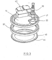
- Fig. 3 shows the stiffening element 10 in its function as a carrier element for components 38, 42 of the pitch system.
- the pitch drive 38 of the pitch system is secured to the mounting stud 20 and passes through the stiffening element 10 to mesh with a pinion 47 in the toothing 35 of the inner ring of the pitch rotary joint 32.
- Control cabinets 42 for a power supply and control, for example for a converter and for a rechargeable battery, are in Fig. 3 only shown schematically. Both the Pitch drive and the cabinets 42 are preassembled on the stiffening element 10 and can be tested independently of the rotor hub housing.
- a second stiffening element 44 is additionally shown.
- the stiffening element 44 corresponds with its through holes 46 through the through holes in the inner ring of the pitch rotary joint.
- the stiffening element 44 is bolted between the pitch turning joint and blade root of the rotor blade (not shown).
- the stiffening element 10 offers a number of advantages.
- the casting-technical effort in the manufacture of the rotor hub housing 28 is significantly reduced, since the stiffening elements 10 and the rotor hub housing 28 are molded separately from each other. This reduces the manufacturing costs and the casting quality is improved.
- By mounting components of the pitch system on the stiffening element 10 additional support structures that previously had to be provided for mounting the components are avoided.
- the assembly is simplified because during assembly of the stiffening element 10 and the components of the pitch system are mounted directly.
- the rotor blade-side stiffening element 44 is formed so that it (not shown) together with the rotor blade root has approximately the same rigidity as the rotor hub housing 28 and the rotor hub side stiffening element 10, resulting in similar stiffness ratios at the connections of inner and outer ring.
Landscapes
- Engineering & Computer Science (AREA)
- Life Sciences & Earth Sciences (AREA)
- Sustainable Development (AREA)
- Sustainable Energy (AREA)
- Chemical & Material Sciences (AREA)
- Combustion & Propulsion (AREA)
- Mechanical Engineering (AREA)
- General Engineering & Computer Science (AREA)
- Physics & Mathematics (AREA)
- Fluid Mechanics (AREA)
- Wind Motors (AREA)
Abstract
Description
- Die vorliegende Erfindung betrifft eine Windenergieanlage mit einem Rotornabengehäuse, das eine Pitchdrehverbindung aufweist.
- Bei der Pitchdrehverbindung, auch als Pitchlager bezeichnet, handelt es sich um ein Wälzlager mit einem inneren und äußeren Ring, wobei einer der Ringe mit dem Rotomabengehäuse und der andere Ring mit dem Rotorblatt verbunden ist. Über ein Pitchsystem, das bevorzugt aus einem Pitchantrieb, einer Pitchsteuerung und beispielsweise einer Hilfsstromversorgung besteht, wird das Rotorblatt um seine Längsachse gedreht und so dessen Anstellwinkel zum Wind eingestellt.
- Bekannte Konstruktionen für das Rotomabengehäuse bestehen aus einem Gußkörper mit einem Flansch zur Montage der Pitchdrehverbindung. Erich Hau beschreibt in Windkraftanlagen, Grundlagen, Technik, Einsatz, Wirtschaftlichkeit, 3. Auflage, Springer-Verlag Berlin in Kapitel 7.5, daß die Qualität und das Gewicht der Rotorblätter nebst der eigentlichen Rotorblattbauweise wesentlich durch die Konstruktion des Blattanschlusses zur Rotornabe bestimmt werde.
- Aus
DE 10 2004 023 773 B3 ist bekannt, die Pitchdrehverbindung mit einem Innenring auszubilden, der fest mit der Rotornabe verbunden ist. Der mit dem Rotorblatt verbundene Außenring besitzt eine Außenverzahnung, die zum Verstellen des Rotorblatts kämmend im Eingriff mit einem Antriebsritzel des Pitchsystems steht. - Aus
DE 10 2004 017 323 A1 ist ein Blattanschluß für ein Rotorblatt bekannt, bei dem eine Arretiereinrichtung vorgesehen ist, die das Rotorblatt mit einer vorgegebenen Winkelstellung spielfrei hält. - Aus
WO 2004/090326 A1 ist ein Rotornabenkörper bekannt, der eine einstückig ausgeformte, dreiarmige Versteifung im Bereich des Rotorblattanschlusses besitzt. - Aus
DE 20 2004 003 521 U1 ist ein Rotornabenkörper für eine Windenergieanlage bekannt, der mit Ringflanschen zur Befestigung einer Pitchdrehverbindung ausgebildet ist. Innerhalb der Ringflansche ist jeweils ein Aussteifungsschott vorgesehen, das entweder als einstückiges Gußteil mit dem Rotomabengehäuse ausgebildet oder als eigenständiges Bauteil mit der Rotornabe verschweiß- oder verschraubbar ist. Das Aussteifungsschott ist in dem Rotomabengehäuse an einer der Rotorwelle zugewandten Seite angeordnet. - Der Erfindung liegt die Aufgabe zugrunde, ein Versteifungselement für ein Rotornabengehäuse bereitzustellen, das die Montage der Windenergieanlage vereinfacht.
- Erfindungsgemäß wird die Aufgabe durch eine Windenergieanlage mit den Merkmalen aus Anspruch 1 gelöst. Vorteilhafte Ausgestaltungen bilden den Gegenstand der Unteransprüche.
- Die erfindungsgemäße Windenergieanlage besitzt ein Rotornabengehäuse, an dem über Verbindungsmittel mindestens eine Pitchdrehverbindung anbringbar ist. Ein Rotorblatt ist mit seiner Blattwurzel an der Pitchdrehverbindung befestigt, bevorzugt mit dieser verschraubt.
- Erfindungsgemäß ist ein Versteifungselement vorgesehen, das zwischen der Pitchdrehverbindung und dem Rotomabengehäuse angeordnet und über Verbindungsmittel an diesem befestigt ist. Das erfindungsgemäße Versteifungselement ist als separates Bauteil ausgebildet und besitzt den besonderen Vorteil, daß es gemeinsam mit der Pitchdrehverbindung an dem Rotomabengehäuse montiert werden kann. Die Montage erfolgt hierbei vorzugsweise über dieselben Verbindungsmittel, mit denen die Pitchdrehverbindung an dem Rotomabengehäuse befestigt ist, wobei das Versteifungselement gemeinsam mit der Pitchdrehverbindung bevorzugt an das Rotomabengehäuse geschraubt wird. Ein weiterer Vorteil des erfindungsgemäßen Versteifungselements besteht darin, daß im Gegensatz zu einem einstückig gegossenen Rotomabengehäuse der Grundkörper des Rotornabengehäuses und die Versteifungselemente gießtechnisch wesentlich einfacher herstellbar sind.
- Zweckmäßigerweise besitzt das Versteifungselement kreisförmig angeordnete Durchgangsbohrungen, die zur Aufnahme von Schrauben vorgesehen sind.
- In einer bevorzugten Ausgestaltung dient das Versteifungselement zugleich als Trägerelement für Komponenten des Pitchsystems. Die Komponenten können unabhängig auf das Versteifungselement montiert werden. Auch kann vor einer Montage an das Rotornabengehäuse das Versteifungselement unabhängig getestet und geprüft werden.
- Bevorzugt ist das Versteifungselement in Form eines Rings ausgebildet. Auch kann es in Form einer Scheibe, Platte oder Wanne ausgebildet sein, wobei dann ein oder mehrere Durchbrüche in dem Versteifungselement vorgesehen werden können.
- In einer bevorzugten Ausgestaltung sind Pitchdrehverbindung und Rotorblatt im Bereich der Blattwurzel einerseits und Rotornabengehäuse sowie Versteifungselement andererseits derart gestaltet, daß ihre Steifigkeiten einander entsprechen. Um rotorblatt- und rotornabenseitig die gleiche Steifigkeit zu erzielen, kann ein zusätzliches Versteifungselement rotorblattseitig zwischen der Pitchdrehverbindung und der Rotorblattwurzel vorgesehen sein. Die Pitchdrehverbindung ist bevorzugt als Wälzlager mit einem Innenring und einem Außenring ausgebildet, wobei beispielsweise der Außenring an der Rotornabe befestigt und der Innenring mit dem Rotorblatt und ggf. einem rotorblattseitigen Versteifungselement verbunden ist. Die Pitchdrehverbindung erfährt für beide Ringe eine annähernd gleiche Steifigkeit. Hierdurch wird vermieden, daß an Innenring und Außenring ungleiche Kräfte angreifen, die die Pitchdrehverbindung ungünstig belasten.
- Ein bevorzugtes Ausführungsbeispiel wird nachfolgend anhand der Zeichnung näher erläutert.
- Es zeigt:
- Fig. 1
- das erfindungsgemäße Versteifungselement, das als Wanne ausgeführt ist,
- Fig. 2
- die Montage des erfindungsgemäßen Versteifungselements an dem Rotornabengehäuse und
- Fig.3
- das erfindungsgemäße Versteifungselement mit Komponenten des Pitchsystems, der Pitchdrehverbindung und einem rotorblattseitigen zweiten Versteifungselement.
-
Fig. 1 zeigt ein Versteifungselement 10, das bevorzugt aus Stahl oder einem Gußmaterial hergestellt ist. Als Gußmaterial bietet sich Gußeisen mit Kugelgraphit an, beispielsweise entsprechend DIN 1563 (beispielsweise EN-GJS-400-18). Das Versteifungselement 10 ist in einem umlaufenden Rand 12 deutlich dicker ausgebildet als in seinem zentralen Bereich 14. Der zentrale Bereich 14 besitzt einen Durchstieg 16, der in das Rotorblatt führt. Der umlaufende Ring 12 ist mit langlochförmigen Durchbrechungen 18 versehen, die zur Montage der Rotorblattschrauben benötigt werden. In einem am Rand liegenden Bereich ist der umlaufende Ring 12 mit einem Befestigungsstutzen 20 zur Anbringung eines Pitchantriebs 38 versehen. In diesem Bereich ist der umlaufende Ring 12 in radialer Richtung breiter als im übrigen Bereich des Versteifungselements. Umlaufend ist das Versteifungselement 10 in seinen Flachseiten jeweils mit außen liegenden Flanschflächen 22, 24 versehen. InFig. 1 ist die Flanschfläche 22, die zum Rotornabengehäuse hinweist, dargestellt. InFig. 2 ist die gegenüberliegende Flanschfläche 24 zu erkennen, die von dem Rotornabengehäuse fortweist. Das Versteifungselement 10 besitzt kreisförmig angeordnete Durchgangsbohrungen 26, durch die Befestigungsbolzen (nicht dargestellt) bei der Montage des Versteifungselements geführt sind. -
Fig. 2 zeigt einen Rotornabengehäuse 28, das an seinen drei Ansätzen für die Rotorblätter jeweils mit einem Versteifungselement 10 ausgestattet ist. Die Ansätze des Rotornabengehäuses 28 besitzen jeweils zur Anbringung des Versteifungselements und der Pitchdrehverbindung einen Montageflansch 30, aus dem Befestigungsbolzen 33 vorstehen. -
Fig. 2 zeigt ferner die Pitchdrehverbindung 32, die aus einem drehbaren Lager mit einem Innenring 34 und einem Außenring 36 besteht. Innenring 34 und Außenring 36 sind jeweils mit kreisförmig angeordneten Durchgangsbohrungen versehen. Die Durchgangsbohrungen des Außenkranzes entsprechen den Durchgangsbohrungen 26 des Versteifungselements. Die oben erwähnten Befestigungsbolzen 33 an dem Montageflansch 30 reichen durch das Versteifungselement 10 und durch den Außenring 36 der Pitchdrehverbindung 32 hindurch. Das Versteifungselement 10 und die Pitchdrehverbindung 32 sind über Muttern 31 an den Befestigungsbolzen gesichert. Der Innenring 34 der Pitchdrehverbindung 32 ist ebenfalls mit kreisförmig angeordneten Durchgangsbohrungen versehen. Der Innenring 34 besitzt auf seiner Innenseite eine Verzahnung 35, über die mit Hilfe eines Pitchantriebs der Innenring 34 relativ zum Außenring 36 gedreht und damit die Winkelstellung des Rotorblatts eingestellt werden kann. Das Versteifungselement 10 und insbesondere dessen umlaufender Ring 12 sind dabei so ausgebildet, daß diese mit dem Innenring nicht in Berührung kommen. -
Fig. 3 zeigt das Versteifungselement 10 in seiner Funktion als Trägerelement für Komponenten 38, 42 des Pitchsystems. Der Pitchantrieb 38 des Pitchsystems ist an dem Befestigungsstutzen 20 befestigt und reicht durch das Versteifungselement 10 hindurch, um mit einem Ritzel 47 in der Verzahnung 35 des Innenrings der Pitchdrehverbindung 32 zu kämmen. Schaltschränke 42 für eine Energieversorgung und Steuerung, beispielsweise für einen Umrichter und für einen Akkumulator, sind inFig. 3 lediglich schematisch dargestellt. Sowohl der Pitchantrieb als auch die Schaltschränke 42 sind an dem Versteifungselement 10 vormontiert und können unabhängig von dem Rotornabengehäuse getestet werden. - In
Fig. 3 ist ein zweites Versteifungselement 44 zusätzlich dargestellt. Das Versteifungselement 44 entspricht mit seinen Durchgangsbohrungen 46 den Durchgangsbohrungen im Innenring der Pitchdrehverbindung. Das Versteifungselement 44 wird zwischen Pitchdrehverbindung und Blattwurzel des Rotorblatts (nicht dargestellt) verschraubt. - Das erfindungsgemäße Versteifungselement 10 bietet eine Reihe von Vorteilen. So ist der gießtechnische Aufwand bei der Herstellung des Rotornabengehäuses 28 deutlich vermindert, da die Versteifungselemente 10 und das Rotornabengehäuse 28 separat voneinander gegossen werden. Dadurch reduzieren sich die Herstellungskosten und die Gußqualität wird verbessert. Durch die Montage von Komponenten des Pitchsystems auf dem Versteifungselement 10 werden zusätzliche Trägerkonstruktionen, die bisher zur Montage der Komponenten vorgesehen werden mußten, vermieden. Auch die Montage wird vereinfacht, da bei der Montage des Versteifungselements 10 auch direkt die Komponenten des Pitchsystems montiert werden.
- Das rotorblattseitige Versteifungselement 44 ist so ausgebildet, daß es zusammen mit der Rotorblattwurzel (nicht dargestellt) eine annähernd gleiche Steifigkeit wie das Rotornabengehäuse 28 und das rotornabenseitige Versteifungselement 10 besitzt, wodurch sich an den Anschlüssen von Innen- und Außenring ähnliche Steifigkeitsverhältnisse ergeben. Durch dieses Zusammenwirken der Versteifungselemente werden die auf die Pitchdrehverbindung 32 einwirkenden Belastungen minimiert und deren Lebensdauer erhöht.
Claims (14)
- Windenergieanlage mit einem Rotomabengehäuse (28), das über Verbindungsmittel mit mindestens einer Pitchdrehverbindung (32) verbindbar ist, und mit mindestens einem Rotorblatt, dessen Blattwurzel mit der Pitchdrehverbindung verbunden ist,
dadurch gekennzeichnet, daß
ein Versteifungselement (10) vorgesehen ist, das zwischen der Pitchdrehverbindung (32) und dem Rotomabengehäuse (28) befestigt ist. - Windenergieanlage nach Anspruch 1, dadurch gekennzeichnet, daß das Versteifungselement (10) kreisförmig angeordnete Durchgangsbohrungen (26) aufweist.
- Windenergieanlage nach Anspruch 1 oder 2, dadurch gekennzeichnet, daß zur Verbindung von Versteifungselement (10) und Pitchdrehverbindung (32) an dem Rotornabengehäuse (28) dieselben Verbindungsmittel vorgesehen sind.
- Windenergieanlage nach einem der Ansprüche 1 bis 3, dadurch gekennzeichnet, daß als Verbindungsmittel Schrauben (33) vorgesehen sind.
- Windenergieanlage nach einem der Ansprüche 1 bis 4, dadurch gekennzeichnet, daß das Versteifungselement (10) Komponenten (38, 40, 42, 43) des Pitchsystems trägt.
- Windenergieanlage nach einem der Ansprüche 1 bis 5, dadurch gekennzeichnet, daß das Versteifungselement (10) die Form eines Rings aufweist.
- Windenergieanlage nach einem der Ansprüche 1 bis 5, dadurch gekennzeichnet, daß das Versteifungselement die Form einer Platte, Scheibe oder Wanne aufweist.
- Windenergieanlage nach Anspruch 7, dadurch gekennzeichnet, daß das Versteifungselement (10) eine oder mehrere Durchbrechungen (16) aufweist.
- Windenergieanlage nach Anspruch 8, dadurch gekennzeichnet, daß die oder eine der Durchbrechungen (16) als Mannloch ausgebildet ist.
- Windenergieanlage nach einem der Ansprüche 1 bis 9, dadurch gekennzeichnet, daß das Versteifungselement aus Metall hergestellt ist.
- Windenergieanlage nach einem der Ansprüche 1 bis 10, dadurch gekennzeichnet, daß die Verbindung von Rotornabengehäuse (28) und Versteifungselement (10) und das an der Pitchdrehverbindung befestigte Rotorblatt im Bereich seiner Blattwurzel annähernd gleiche Steifigkeit besitzen.
- Windenergieanlage nach Anspruch 11, dadurch gekennzeichnet, daß rotorblattseitig von der Pitchdrehverbindung (32) ein zusätzliches Versteifungselement (44) an dem Rotorblatt vorgesehen ist.
- Windenergieanlage nach Anspruch 12, dadurch gekennzeichnet, daß die Pitchdrehverbindung (32) rotorblattseitig und rotornabenseitig jeweils mit einem Flansch verbunden ist, die beide annähernd die gleiche Steifigkeit besitzen.
- Windenergieanlage nach einem der Ansprüche 1 bis 13, dadurch gekennzeichnet, daß das Versteifungselement Durchbrechungen (18) für die Montage der Verbindungsmittel zwischen der Pitchdrehverbindung (32) und einem Rotorblatt der Windenergieanlage aufweist.
Applications Claiming Priority (1)
| Application Number | Priority Date | Filing Date | Title |
|---|---|---|---|
| DE102007008166A DE102007008166A1 (de) | 2007-02-14 | 2007-02-14 | Windenergieanlage mit einer Pitchdrehverbindung |
Publications (3)
| Publication Number | Publication Date |
|---|---|
| EP1959132A2 true EP1959132A2 (de) | 2008-08-20 |
| EP1959132A3 EP1959132A3 (de) | 2010-06-23 |
| EP1959132B1 EP1959132B1 (de) | 2014-02-26 |
Family
ID=39590878
Family Applications (1)
| Application Number | Title | Priority Date | Filing Date |
|---|---|---|---|
| EP07021231.1A Not-in-force EP1959132B1 (de) | 2007-02-14 | 2007-10-31 | Windenergieanlage mit einer Pitchdrehverbindung |
Country Status (4)
| Country | Link |
|---|---|
| US (1) | US7874800B2 (de) |
| EP (1) | EP1959132B1 (de) |
| CN (1) | CN101245762B (de) |
| DE (1) | DE102007008166A1 (de) |
Cited By (6)
| Publication number | Priority date | Publication date | Assignee | Title |
|---|---|---|---|---|
| WO2010083906A2 (de) | 2009-01-23 | 2010-07-29 | Avantis Ltd. | Polrad einer windenergieanlage |
| EP2476899A1 (de) * | 2011-01-17 | 2012-07-18 | Siemens Aktiengesellschaft | Windturbinenschaufellager |
| WO2012130240A1 (en) * | 2011-03-30 | 2012-10-04 | Vestas Wind Systems A/S | A hub for a wind turbine |
| EP2530301A1 (de) * | 2011-05-31 | 2012-12-05 | General Electric Company | Versteifungselement des Blattwürzels und ein Montageverfahren eines der Versteifungselement beinhaltenden Blattes |
| GB2526277A (en) * | 2014-05-19 | 2015-11-25 | Marine Current Turbines Ltd | Modular turbine mounting |
| EP2541049A3 (de) * | 2011-06-24 | 2018-01-03 | General Electric Company | Nabenanordnung zur Verwendung mit einer Windturbine und Herstellungsverfahren dafür |
Families Citing this family (35)
| Publication number | Priority date | Publication date | Assignee | Title |
|---|---|---|---|---|
| DE102009044036A1 (de) * | 2009-09-17 | 2011-04-14 | Ssb Wind Systems Gmbh & Co. Kg | Windkraftanlage |
| US8092171B2 (en) * | 2009-09-30 | 2012-01-10 | General Electric Company | Systems and methods for assembling a pitch assembly for use in a wind turbine |
| KR101078437B1 (ko) * | 2009-12-23 | 2011-10-31 | 삼성중공업 주식회사 | 풍력 발전기 |
| DE102010010639A1 (de) * | 2010-03-09 | 2011-09-15 | Schaeffler Technologies Gmbh & Co. Kg | Drehverbindung eines Rotorblattes mit der Rotornabe einer Windkraftanlage |
| US20110142618A1 (en) * | 2010-10-29 | 2011-06-16 | Bradley Graham Moore | Wind turbine pitch assembly enclosure system |
| US9631605B2 (en) | 2010-11-26 | 2017-04-25 | Vestas Wind Systems A/S | Pitch system for a wind turbine |
| EP2532882A1 (de) * | 2011-06-10 | 2012-12-12 | General Electric Company | System und Verfahren zur Montage einer Windturbine mit einer Neigungsanordnung |
| DK2574781T3 (da) * | 2011-09-30 | 2014-08-11 | Alstom Renovables Espana Sl | Vindmøllerotor |
| CN103184977B (zh) * | 2011-12-31 | 2015-11-25 | 新疆金风科技股份有限公司 | 风机叶片连接方法、风机叶轮及风力发电机组 |
| BR112014017332A2 (pt) * | 2012-01-13 | 2017-06-13 | GmbH youWINenergy | rotor de turbina eólica |
| US9109578B2 (en) | 2012-06-12 | 2015-08-18 | General Electric Company | Root extender for a wind turbine rotor blade |
| US9074581B2 (en) | 2012-06-12 | 2015-07-07 | General Electric Company | Cone angle insert for wind turbine rotor |
| ES2435340B1 (es) * | 2012-06-15 | 2014-12-05 | Gamesa Innovation & Technology, S.L. | Sistema de fijación para aerogeneradores y método de colocación del mismo |
| EP2703644B1 (de) * | 2012-08-27 | 2016-08-03 | Alstom Wind, S.L.U. | Winkelpositionierungssystem für eine Windturbine |
| DK2703666T3 (en) * | 2012-08-27 | 2018-07-23 | Ge Renewable Tech | Rotary system for a wind turbine |
| US20140064971A1 (en) * | 2012-08-29 | 2014-03-06 | General Electric Company | Stiffener plate for a wind turbine |
| DE102013003634B4 (de) | 2013-03-05 | 2022-10-20 | Nordex Energy Se & Co. Kg | Windenergieanlagenrotorblatt mit einem Blattanschlussbereich |
| US9551324B2 (en) | 2013-06-20 | 2017-01-24 | General Electric Company | Pitch bearing assembly with stiffener |
| US9951815B2 (en) | 2013-06-27 | 2018-04-24 | General Electric Company | Pitch bearing assembly with stiffener |
| US9523348B2 (en) | 2013-09-25 | 2016-12-20 | General Electric Company | Rotor blade assembly with shim plate for mitigation pitch bearing loads |
| DK177926B1 (en) * | 2013-12-20 | 2015-01-12 | Fritz Schur Energy As | Pitch actuator arrangement |
| DE102014009306A1 (de) * | 2014-06-26 | 2015-12-31 | Senvion Gmbh | Drehwerk zur Verdrehung eines drehbar an einer Windenergieanlage gelagerten Bauteils |
| CN104595107A (zh) * | 2014-12-08 | 2015-05-06 | 北车风电有限公司 | 一种风力发电机组叶片变桨机构 |
| DE102016203269A1 (de) * | 2016-02-29 | 2017-08-31 | Innogy Se | Windkraftanlage mit verbesserter Rotorblattverschraubung |
| US10598159B2 (en) | 2016-05-06 | 2020-03-24 | General Electric Company | Wind turbine bearings |
| EP3542050A1 (de) | 2017-01-19 | 2019-09-25 | Siemens Gamesa Renewable Energy A/S | Klingenmontageanordnung |
| DE102018108610A1 (de) * | 2018-04-11 | 2019-10-17 | Wobben Properties Gmbh | Rotornabe einer Windenergieanlage, sowie Verfahren zur Montage einer solchen Rotornabe |
| DE102018113760B4 (de) * | 2018-06-08 | 2023-02-23 | Aerovide Gmbh | Rotorlagergehäuse und Windenergieanlage mit Rotorlagergehäuse |
| CN109113938B (zh) * | 2018-10-10 | 2024-03-15 | 明阳智慧能源集团股份公司 | 风电机组用的分段式变桨轴承加强法兰及其空中安装方法 |
| DE102018131321A1 (de) | 2018-12-07 | 2020-06-10 | Wobben Properties Gmbh | Windenergieanlage mit Tragstruktur |
| US11454219B2 (en) * | 2019-05-10 | 2022-09-27 | General Electric Company | Rotor assembly having a pitch bearing with a stiffener ring |
| EP3786443A1 (de) * | 2019-08-30 | 2021-03-03 | General Electric Renovables España S.L. | Nabenanordnung für einen rotor einer windturbine |
| DE102023103435A1 (de) | 2023-02-13 | 2024-08-14 | Thyssenkrupp Ag | Lagereinheit und Windenergieanlage mit einer Lagereinheit |
| LU103069B1 (de) | 2023-02-13 | 2024-08-13 | Thyssenkrupp Ag | Lagereinheit und Windenergieanlage mit einer Lagereinheit |
| CN120958231A (zh) | 2023-02-13 | 2025-11-14 | 蒂森克虏伯罗特艾德德国有限公司 | 轴承单元以及具有轴承单元的风力涡轮机 |
Family Cites Families (13)
| Publication number | Priority date | Publication date | Assignee | Title |
|---|---|---|---|---|
| US5660527A (en) * | 1995-10-05 | 1997-08-26 | The Wind Turbine Company | Wind turbine rotor blade root end |
| DE10034958A1 (de) * | 2000-07-19 | 2002-02-07 | Aloys Wobben | Rotorblattnabe |
| DE10141667A1 (de) * | 2001-08-25 | 2003-03-13 | Aloys Wobben | Vorrichtung zum Verdrehen von zwei Bauteilen gegeneinander |
| DE10201726B4 (de) * | 2002-01-18 | 2004-10-21 | Wobben, Aloys, Dipl.-Ing. | Windenergieanlage |
| WO2003064854A1 (en) * | 2002-01-31 | 2003-08-07 | Neg Micon A/S | Blade-hub for a wind turbine |
| DE10351524A1 (de) * | 2002-11-05 | 2004-08-12 | Roland Weitkamp | Rotorlagerung für eine Windenergieanlage |
| US7244102B2 (en) * | 2003-04-12 | 2007-07-17 | General Electric Company | Reinforced hub for the rotor of a wind energy turbine |
| DE202004003521U1 (de) | 2004-03-06 | 2004-06-24 | W2E Wind To Engergy Gmbh | Innenbegehbare Rotornabe |
| DE102004017323A1 (de) | 2004-04-06 | 2005-11-03 | Repower Systems Ag | Windenergieanlage |
| DE102004023773B3 (de) | 2004-05-11 | 2005-11-17 | Repower Systems Ag | Windenergieanlage |
| DE202005007450U1 (de) * | 2004-05-17 | 2005-07-14 | Hehenberger, Gerald, Dipl.-Ing. | Adapter zum Befestigen von Rotorblättern einer Windkraftanlage an einer Rotornabe und Windkraftanlage mit solchen Adaptern |
| EP1907692B2 (de) * | 2005-07-05 | 2022-12-07 | Vestas Wind Systems A/S | Windturbinenblattlager und verwendung davon |
| PL1933027T3 (pl) | 2006-12-08 | 2011-10-31 | Stx Heavy Ind Co Ltd | Piasta wirnika turbiny wiatrowej |
-
2007
- 2007-02-14 DE DE102007008166A patent/DE102007008166A1/de not_active Ceased
- 2007-06-08 US US11/760,046 patent/US7874800B2/en not_active Expired - Fee Related
- 2007-10-31 EP EP07021231.1A patent/EP1959132B1/de not_active Not-in-force
- 2007-12-12 CN CN2007101997563A patent/CN101245762B/zh not_active Expired - Fee Related
Cited By (11)
| Publication number | Priority date | Publication date | Assignee | Title |
|---|---|---|---|---|
| WO2010083906A2 (de) | 2009-01-23 | 2010-07-29 | Avantis Ltd. | Polrad einer windenergieanlage |
| WO2010083906A3 (de) * | 2009-01-23 | 2010-11-25 | Avantis Ltd. | Polrad einer windenergieanlage |
| CN102656781A (zh) * | 2009-01-23 | 2012-09-05 | 广西银河风力发电有限公司 | 风能发电机的磁极转子 |
| CN102656781B (zh) * | 2009-01-23 | 2015-06-17 | 广西银河风力发电有限公司 | 风能发电机的磁极转子 |
| EP2476899A1 (de) * | 2011-01-17 | 2012-07-18 | Siemens Aktiengesellschaft | Windturbinenschaufellager |
| WO2012130240A1 (en) * | 2011-03-30 | 2012-10-04 | Vestas Wind Systems A/S | A hub for a wind turbine |
| EP2691646B1 (de) | 2011-03-30 | 2017-07-12 | Vestas Wind Systems A/S | Nabe für eine windturbine |
| US9739258B2 (en) | 2011-03-30 | 2017-08-22 | Vestas Wind Systems A/S | Hub for a wind turbine |
| EP2530301A1 (de) * | 2011-05-31 | 2012-12-05 | General Electric Company | Versteifungselement des Blattwürzels und ein Montageverfahren eines der Versteifungselement beinhaltenden Blattes |
| EP2541049A3 (de) * | 2011-06-24 | 2018-01-03 | General Electric Company | Nabenanordnung zur Verwendung mit einer Windturbine und Herstellungsverfahren dafür |
| GB2526277A (en) * | 2014-05-19 | 2015-11-25 | Marine Current Turbines Ltd | Modular turbine mounting |
Also Published As
| Publication number | Publication date |
|---|---|
| CN101245762A (zh) | 2008-08-20 |
| US7874800B2 (en) | 2011-01-25 |
| CN101245762B (zh) | 2012-10-31 |
| US20080191488A1 (en) | 2008-08-14 |
| EP1959132B1 (de) | 2014-02-26 |
| EP1959132A3 (de) | 2010-06-23 |
| DE102007008166A1 (de) | 2008-08-21 |
Similar Documents
| Publication | Publication Date | Title |
|---|---|---|
| EP1959132B1 (de) | Windenergieanlage mit einer Pitchdrehverbindung | |
| EP1959129B1 (de) | Windenergieanlage | |
| EP1398499B1 (de) | Befestigung von Rotorblättern an der Nabe einer Windenergieanlage | |
| DE10324166B4 (de) | Rotorblattanschluss | |
| EP2545273A2 (de) | Drehverbindung eines rotorblattes mit der rotornabe einer windkraftanlage | |
| EP3455493B1 (de) | Windenergieanlagen-rotorblatt, und windenergieanlage mit selbigem | |
| EP3396154A1 (de) | Blattadapter für windenergieanlagen | |
| DE102010039778A1 (de) | Rotorblatt für Windenergieanlagen | |
| WO2013107639A1 (de) | Rotorflügel für eine turbine | |
| EP3034864B1 (de) | Rotornabe für einen eine rotorachse aufweisenden rotor einer windenergieanlage | |
| EP4702238A1 (de) | Vorrichtung zur befestigung eines rotorblattes an einem nabenkörper und mehrteilige nabenanordnung für eine windenergieanlage | |
| LU103069B1 (de) | Lagereinheit und Windenergieanlage mit einer Lagereinheit | |
| LU103210B1 (de) | Nabenanordnung für eine Windenergieanlage | |
| EP4060187B1 (de) | Rotorlagergehäuse, rotorlageranordnung und windenergieanlage | |
| BE1031546B1 (de) | Vorrichtung zur Befestigung eines Rotorblattes an einem Nabenkörper und mehrteilige Nabenanordnung für eine Windenergieanlage | |
| DE102023103435A1 (de) | Lagereinheit und Windenergieanlage mit einer Lagereinheit | |
| EP4665967A1 (de) | Lagereinheit und windenergieanlage mit einer lagereinheit | |
| EP3891385B1 (de) | Windenergieanlage mit tragstruktur | |
| EP3431749B1 (de) | Extender zum befestigen eines rotorblatts an einem rotornabengehäuse einer windenergieanlage, verfahren zur herstellung eines extenders und verfahren zur montage eines extenders | |
| WO2011015216A1 (de) | Windenergieanlage | |
| DE102024123253A1 (de) | Großwälzlager als Blatt-, Azimut- oder Hauptlager für eine Windenergieanlage | |
| EP1467095A2 (de) | Lager für eine Windenenergieanlage | |
| DE102023130453A1 (de) | Nabenanordnung für eine Windenergieanlage | |
| DE102023110410A1 (de) | Vorrichtung zur Befestigung eines Rotorblattes an einem Nabenkörper und mehrteilige Nabenanordnung für eine Windenergieanlage | |
| DE202016105921U1 (de) | Arretiervorrichtung für einen Triebstrang |
Legal Events
| Date | Code | Title | Description |
|---|---|---|---|
| PUAI | Public reference made under article 153(3) epc to a published international application that has entered the european phase |
Free format text: ORIGINAL CODE: 0009012 |
|
| AK | Designated contracting states |
Kind code of ref document: A2 Designated state(s): AT BE BG CH CY CZ DE DK EE ES FI FR GB GR HU IE IS IT LI LT LU LV MC MT NL PL PT RO SE SI SK TR |
|
| AX | Request for extension of the european patent |
Extension state: AL BA HR MK RS |
|
| PUAL | Search report despatched |
Free format text: ORIGINAL CODE: 0009013 |
|
| AK | Designated contracting states |
Kind code of ref document: A3 Designated state(s): AT BE BG CH CY CZ DE DK EE ES FI FR GB GR HU IE IS IT LI LT LU LV MC MT NL PL PT RO SE SI SK TR |
|
| AX | Request for extension of the european patent |
Extension state: AL BA HR MK RS |
|
| RIC1 | Information provided on ipc code assigned before grant |
Ipc: F03D 1/06 20060101ALI20100518BHEP Ipc: F03D 11/04 20060101ALI20100518BHEP Ipc: F03D 11/00 20060101ALI20100518BHEP Ipc: F03D 7/02 20060101AFI20080716BHEP |
|
| 17P | Request for examination filed |
Effective date: 20101214 |
|
| AKX | Designation fees paid |
Designated state(s): AT BE BG CH CY CZ DE DK EE ES FI FR GB GR HU IE IS IT LI LT LU LV MC MT NL PL PT RO SE SI SK TR |
|
| RIC1 | Information provided on ipc code assigned before grant |
Ipc: F03D 11/04 20060101ALI20130312BHEP Ipc: F03D 7/02 20060101AFI20130312BHEP Ipc: F03D 11/00 20060101ALI20130312BHEP Ipc: F03D 1/06 20060101ALI20130312BHEP |
|
| GRAP | Despatch of communication of intention to grant a patent |
Free format text: ORIGINAL CODE: EPIDOSNIGR1 |
|
| INTG | Intention to grant announced |
Effective date: 20130426 |
|
| GRAP | Despatch of communication of intention to grant a patent |
Free format text: ORIGINAL CODE: EPIDOSNIGR1 |
|
| INTG | Intention to grant announced |
Effective date: 20131217 |
|
| GRAS | Grant fee paid |
Free format text: ORIGINAL CODE: EPIDOSNIGR3 |
|
| GRAA | (expected) grant |
Free format text: ORIGINAL CODE: 0009210 |
|
| RAP1 | Party data changed (applicant data changed or rights of an application transferred) |
Owner name: NORDEX ENERGY GMBH |
|
| AK | Designated contracting states |
Kind code of ref document: B1 Designated state(s): AT BE BG CH CY CZ DE DK EE ES FI FR GB GR HU IE IS IT LI LT LU LV MC MT NL PL PT RO SE SI SK TR |
|
| REG | Reference to a national code |
Ref country code: GB Ref legal event code: FG4D Free format text: NOT ENGLISH |
|
| REG | Reference to a national code |
Ref country code: CH Ref legal event code: EP |
|
| REG | Reference to a national code |
Ref country code: AT Ref legal event code: REF Ref document number: 653779 Country of ref document: AT Kind code of ref document: T Effective date: 20140315 |
|
| REG | Reference to a national code |
Ref country code: IE Ref legal event code: FG4D Free format text: LANGUAGE OF EP DOCUMENT: GERMAN |
|
| REG | Reference to a national code |
Ref country code: DE Ref legal event code: R096 Ref document number: 502007012781 Country of ref document: DE Effective date: 20140410 |
|
| REG | Reference to a national code |
Ref country code: NL Ref legal event code: VDEP Effective date: 20140226 |
|
| REG | Reference to a national code |
Ref country code: LT Ref legal event code: MG4D |
|
| PG25 | Lapsed in a contracting state [announced via postgrant information from national office to epo] |
Ref country code: IS Free format text: LAPSE BECAUSE OF FAILURE TO SUBMIT A TRANSLATION OF THE DESCRIPTION OR TO PAY THE FEE WITHIN THE PRESCRIBED TIME-LIMIT Effective date: 20140626 Ref country code: LT Free format text: LAPSE BECAUSE OF FAILURE TO SUBMIT A TRANSLATION OF THE DESCRIPTION OR TO PAY THE FEE WITHIN THE PRESCRIBED TIME-LIMIT Effective date: 20140226 |
|
| PG25 | Lapsed in a contracting state [announced via postgrant information from national office to epo] |
Ref country code: NL Free format text: LAPSE BECAUSE OF FAILURE TO SUBMIT A TRANSLATION OF THE DESCRIPTION OR TO PAY THE FEE WITHIN THE PRESCRIBED TIME-LIMIT Effective date: 20140226 Ref country code: SE Free format text: LAPSE BECAUSE OF FAILURE TO SUBMIT A TRANSLATION OF THE DESCRIPTION OR TO PAY THE FEE WITHIN THE PRESCRIBED TIME-LIMIT Effective date: 20140226 Ref country code: CY Free format text: LAPSE BECAUSE OF FAILURE TO SUBMIT A TRANSLATION OF THE DESCRIPTION OR TO PAY THE FEE WITHIN THE PRESCRIBED TIME-LIMIT Effective date: 20140226 Ref country code: FI Free format text: LAPSE BECAUSE OF FAILURE TO SUBMIT A TRANSLATION OF THE DESCRIPTION OR TO PAY THE FEE WITHIN THE PRESCRIBED TIME-LIMIT Effective date: 20140226 Ref country code: PT Free format text: LAPSE BECAUSE OF FAILURE TO SUBMIT A TRANSLATION OF THE DESCRIPTION OR TO PAY THE FEE WITHIN THE PRESCRIBED TIME-LIMIT Effective date: 20140626 |
|
| PG25 | Lapsed in a contracting state [announced via postgrant information from national office to epo] |
Ref country code: LV Free format text: LAPSE BECAUSE OF FAILURE TO SUBMIT A TRANSLATION OF THE DESCRIPTION OR TO PAY THE FEE WITHIN THE PRESCRIBED TIME-LIMIT Effective date: 20140226 |
|
| PG25 | Lapsed in a contracting state [announced via postgrant information from national office to epo] |
Ref country code: DK Free format text: LAPSE BECAUSE OF FAILURE TO SUBMIT A TRANSLATION OF THE DESCRIPTION OR TO PAY THE FEE WITHIN THE PRESCRIBED TIME-LIMIT Effective date: 20140226 Ref country code: RO Free format text: LAPSE BECAUSE OF FAILURE TO SUBMIT A TRANSLATION OF THE DESCRIPTION OR TO PAY THE FEE WITHIN THE PRESCRIBED TIME-LIMIT Effective date: 20140226 Ref country code: CZ Free format text: LAPSE BECAUSE OF FAILURE TO SUBMIT A TRANSLATION OF THE DESCRIPTION OR TO PAY THE FEE WITHIN THE PRESCRIBED TIME-LIMIT Effective date: 20140226 Ref country code: EE Free format text: LAPSE BECAUSE OF FAILURE TO SUBMIT A TRANSLATION OF THE DESCRIPTION OR TO PAY THE FEE WITHIN THE PRESCRIBED TIME-LIMIT Effective date: 20140226 |
|
| REG | Reference to a national code |
Ref country code: DE Ref legal event code: R097 Ref document number: 502007012781 Country of ref document: DE |
|
| PG25 | Lapsed in a contracting state [announced via postgrant information from national office to epo] |
Ref country code: ES Free format text: LAPSE BECAUSE OF FAILURE TO SUBMIT A TRANSLATION OF THE DESCRIPTION OR TO PAY THE FEE WITHIN THE PRESCRIBED TIME-LIMIT Effective date: 20140226 Ref country code: PL Free format text: LAPSE BECAUSE OF FAILURE TO SUBMIT A TRANSLATION OF THE DESCRIPTION OR TO PAY THE FEE WITHIN THE PRESCRIBED TIME-LIMIT Effective date: 20140226 Ref country code: SK Free format text: LAPSE BECAUSE OF FAILURE TO SUBMIT A TRANSLATION OF THE DESCRIPTION OR TO PAY THE FEE WITHIN THE PRESCRIBED TIME-LIMIT Effective date: 20140226 |
|
| PLBE | No opposition filed within time limit |
Free format text: ORIGINAL CODE: 0009261 |
|
| STAA | Information on the status of an ep patent application or granted ep patent |
Free format text: STATUS: NO OPPOSITION FILED WITHIN TIME LIMIT |
|
| 26N | No opposition filed |
Effective date: 20141127 |
|
| REG | Reference to a national code |
Ref country code: DE Ref legal event code: R097 Ref document number: 502007012781 Country of ref document: DE Effective date: 20141127 |
|
| PG25 | Lapsed in a contracting state [announced via postgrant information from national office to epo] |
Ref country code: IT Free format text: LAPSE BECAUSE OF FAILURE TO SUBMIT A TRANSLATION OF THE DESCRIPTION OR TO PAY THE FEE WITHIN THE PRESCRIBED TIME-LIMIT Effective date: 20140226 |
|
| PG25 | Lapsed in a contracting state [announced via postgrant information from national office to epo] |
Ref country code: LU Free format text: LAPSE BECAUSE OF FAILURE TO SUBMIT A TRANSLATION OF THE DESCRIPTION OR TO PAY THE FEE WITHIN THE PRESCRIBED TIME-LIMIT Effective date: 20141031 Ref country code: SI Free format text: LAPSE BECAUSE OF FAILURE TO SUBMIT A TRANSLATION OF THE DESCRIPTION OR TO PAY THE FEE WITHIN THE PRESCRIBED TIME-LIMIT Effective date: 20140226 Ref country code: MC Free format text: LAPSE BECAUSE OF FAILURE TO SUBMIT A TRANSLATION OF THE DESCRIPTION OR TO PAY THE FEE WITHIN THE PRESCRIBED TIME-LIMIT Effective date: 20140226 |
|
| REG | Reference to a national code |
Ref country code: CH Ref legal event code: PL |
|
| PG25 | Lapsed in a contracting state [announced via postgrant information from national office to epo] |
Ref country code: BE Free format text: LAPSE BECAUSE OF NON-PAYMENT OF DUE FEES Effective date: 20141031 |
|
| REG | Reference to a national code |
Ref country code: IE Ref legal event code: MM4A |
|
| PG25 | Lapsed in a contracting state [announced via postgrant information from national office to epo] |
Ref country code: LI Free format text: LAPSE BECAUSE OF NON-PAYMENT OF DUE FEES Effective date: 20141031 Ref country code: CH Free format text: LAPSE BECAUSE OF NON-PAYMENT OF DUE FEES Effective date: 20141031 |
|
| REG | Reference to a national code |
Ref country code: FR Ref legal event code: PLFP Year of fee payment: 9 |
|
| PG25 | Lapsed in a contracting state [announced via postgrant information from national office to epo] |
Ref country code: IE Free format text: LAPSE BECAUSE OF NON-PAYMENT OF DUE FEES Effective date: 20141031 |
|
| REG | Reference to a national code |
Ref country code: AT Ref legal event code: MM01 Ref document number: 653779 Country of ref document: AT Kind code of ref document: T Effective date: 20141031 |
|
| PG25 | Lapsed in a contracting state [announced via postgrant information from national office to epo] |
Ref country code: AT Free format text: LAPSE BECAUSE OF NON-PAYMENT OF DUE FEES Effective date: 20141031 |
|
| PG25 | Lapsed in a contracting state [announced via postgrant information from national office to epo] |
Ref country code: BG Free format text: LAPSE BECAUSE OF FAILURE TO SUBMIT A TRANSLATION OF THE DESCRIPTION OR TO PAY THE FEE WITHIN THE PRESCRIBED TIME-LIMIT Effective date: 20140226 |
|
| PG25 | Lapsed in a contracting state [announced via postgrant information from national office to epo] |
Ref country code: GR Free format text: LAPSE BECAUSE OF FAILURE TO SUBMIT A TRANSLATION OF THE DESCRIPTION OR TO PAY THE FEE WITHIN THE PRESCRIBED TIME-LIMIT Effective date: 20140527 |
|
| PG25 | Lapsed in a contracting state [announced via postgrant information from national office to epo] |
Ref country code: HU Free format text: LAPSE BECAUSE OF FAILURE TO SUBMIT A TRANSLATION OF THE DESCRIPTION OR TO PAY THE FEE WITHIN THE PRESCRIBED TIME-LIMIT; INVALID AB INITIO Effective date: 20071031 Ref country code: MT Free format text: LAPSE BECAUSE OF FAILURE TO SUBMIT A TRANSLATION OF THE DESCRIPTION OR TO PAY THE FEE WITHIN THE PRESCRIBED TIME-LIMIT Effective date: 20140226 Ref country code: TR Free format text: LAPSE BECAUSE OF FAILURE TO SUBMIT A TRANSLATION OF THE DESCRIPTION OR TO PAY THE FEE WITHIN THE PRESCRIBED TIME-LIMIT Effective date: 20140226 |
|
| REG | Reference to a national code |
Ref country code: FR Ref legal event code: PLFP Year of fee payment: 10 |
|
| REG | Reference to a national code |
Ref country code: FR Ref legal event code: PLFP Year of fee payment: 11 |
|
| REG | Reference to a national code |
Ref country code: FR Ref legal event code: PLFP Year of fee payment: 12 |
|
| PGFP | Annual fee paid to national office [announced via postgrant information from national office to epo] |
Ref country code: DE Payment date: 20181211 Year of fee payment: 12 |
|
| PGFP | Annual fee paid to national office [announced via postgrant information from national office to epo] |
Ref country code: FR Payment date: 20181023 Year of fee payment: 12 Ref country code: GB Payment date: 20181025 Year of fee payment: 12 |
|
| REG | Reference to a national code |
Ref country code: DE Ref legal event code: R119 Ref document number: 502007012781 Country of ref document: DE |
|
| PG25 | Lapsed in a contracting state [announced via postgrant information from national office to epo] |
Ref country code: DE Free format text: LAPSE BECAUSE OF NON-PAYMENT OF DUE FEES Effective date: 20200501 |
|
| GBPC | Gb: european patent ceased through non-payment of renewal fee |
Effective date: 20191031 |
|
| PG25 | Lapsed in a contracting state [announced via postgrant information from national office to epo] |
Ref country code: GB Free format text: LAPSE BECAUSE OF NON-PAYMENT OF DUE FEES Effective date: 20191031 Ref country code: FR Free format text: LAPSE BECAUSE OF NON-PAYMENT OF DUE FEES Effective date: 20191031 |