EP1959152A2 - Garniture de friction - Google Patents
Garniture de friction Download PDFInfo
- Publication number
- EP1959152A2 EP1959152A2 EP08002097A EP08002097A EP1959152A2 EP 1959152 A2 EP1959152 A2 EP 1959152A2 EP 08002097 A EP08002097 A EP 08002097A EP 08002097 A EP08002097 A EP 08002097A EP 1959152 A2 EP1959152 A2 EP 1959152A2
- Authority
- EP
- European Patent Office
- Prior art keywords
- friction
- friction lining
- particles
- lining
- binder matrix
- Prior art date
- Legal status (The legal status is an assumption and is not a legal conclusion. Google has not performed a legal analysis and makes no representation as to the accuracy of the status listed.)
- Granted
Links
- 239000002245 particle Substances 0.000 claims abstract description 90
- 239000011230 binding agent Substances 0.000 claims abstract description 65
- 239000011159 matrix material Substances 0.000 claims abstract description 51
- 230000005540 biological transmission Effects 0.000 claims abstract description 7
- KXGFMDJXCMQABM-UHFFFAOYSA-N 2-methoxy-6-methylphenol Chemical class [CH]OC1=CC=CC([CH])=C1O KXGFMDJXCMQABM-UHFFFAOYSA-N 0.000 claims description 17
- HBMJWWWQQXIZIP-UHFFFAOYSA-N silicon carbide Chemical compound [Si+]#[C-] HBMJWWWQQXIZIP-UHFFFAOYSA-N 0.000 claims description 13
- 229910010271 silicon carbide Inorganic materials 0.000 claims description 13
- 239000000654 additive Substances 0.000 claims description 11
- 230000000996 additive effect Effects 0.000 claims description 3
- 230000002706 hydrostatic effect Effects 0.000 claims description 2
- 239000010410 layer Substances 0.000 description 34
- 239000005011 phenolic resin Substances 0.000 description 23
- 229920001568 phenolic resin Polymers 0.000 description 20
- -1 polyoxymethylene Polymers 0.000 description 14
- XEEYBQQBJWHFJM-UHFFFAOYSA-N iron Substances [Fe] XEEYBQQBJWHFJM-UHFFFAOYSA-N 0.000 description 11
- 239000000463 material Substances 0.000 description 10
- 229920001721 polyimide Polymers 0.000 description 9
- 239000009719 polyimide resin Substances 0.000 description 9
- 230000000694 effects Effects 0.000 description 8
- 239000003822 epoxy resin Chemical class 0.000 description 7
- 229920000647 polyepoxide Chemical class 0.000 description 7
- 229910000831 Steel Inorganic materials 0.000 description 6
- 125000003118 aryl group Chemical group 0.000 description 6
- 239000012948 isocyanate Substances 0.000 description 6
- 150000002513 isocyanates Chemical group 0.000 description 6
- 238000000034 method Methods 0.000 description 6
- 229920003055 poly(ester-imide) Polymers 0.000 description 6
- 229920006260 polyaryletherketone Polymers 0.000 description 6
- 239000010959 steel Substances 0.000 description 6
- 239000004962 Polyamide-imide Substances 0.000 description 5
- VYPSYNLAJGMNEJ-UHFFFAOYSA-N Silicium dioxide Chemical compound O=[Si]=O VYPSYNLAJGMNEJ-UHFFFAOYSA-N 0.000 description 5
- 239000002783 friction material Substances 0.000 description 5
- 229910052751 metal Inorganic materials 0.000 description 5
- 239000002184 metal Substances 0.000 description 5
- 229920002312 polyamide-imide Polymers 0.000 description 5
- 229920005989 resin Polymers 0.000 description 5
- 239000011347 resin Substances 0.000 description 5
- 239000002904 solvent Substances 0.000 description 5
- 150000004763 sulfides Chemical class 0.000 description 5
- 239000004925 Acrylic resin Chemical class 0.000 description 4
- 229920000178 Acrylic resin Chemical class 0.000 description 4
- 229910018072 Al 2 O 3 Inorganic materials 0.000 description 4
- OKTJSMMVPCPJKN-UHFFFAOYSA-N Carbon Chemical compound [C] OKTJSMMVPCPJKN-UHFFFAOYSA-N 0.000 description 4
- 229910052799 carbon Inorganic materials 0.000 description 4
- 239000010949 copper Substances 0.000 description 4
- 229910003460 diamond Inorganic materials 0.000 description 4
- 239000010432 diamond Substances 0.000 description 4
- 239000006185 dispersion Substances 0.000 description 4
- 239000000945 filler Substances 0.000 description 4
- 239000012530 fluid Substances 0.000 description 4
- 230000006872 improvement Effects 0.000 description 4
- 239000000203 mixture Substances 0.000 description 4
- 230000004048 modification Effects 0.000 description 4
- 238000012986 modification Methods 0.000 description 4
- 239000011701 zinc Substances 0.000 description 4
- 229920002292 Nylon 6 Polymers 0.000 description 3
- 229920002302 Nylon 6,6 Polymers 0.000 description 3
- 239000002033 PVDF binder Substances 0.000 description 3
- 229930040373 Paraformaldehyde Natural products 0.000 description 3
- 239000004696 Poly ether ether ketone Substances 0.000 description 3
- 239000004734 Polyphenylene sulfide Substances 0.000 description 3
- 229910004298 SiO 2 Inorganic materials 0.000 description 3
- RYYWUUFWQRZTIU-UHFFFAOYSA-N Thiophosphoric acid Chemical class OP(O)(S)=O RYYWUUFWQRZTIU-UHFFFAOYSA-N 0.000 description 3
- 239000002318 adhesion promoter Substances 0.000 description 3
- 239000000853 adhesive Substances 0.000 description 3
- 230000001070 adhesive effect Effects 0.000 description 3
- 239000011248 coating agent Substances 0.000 description 3
- 238000000576 coating method Methods 0.000 description 3
- 239000010431 corundum Substances 0.000 description 3
- 229910052593 corundum Inorganic materials 0.000 description 3
- 230000032798 delamination Effects 0.000 description 3
- 150000002148 esters Chemical class 0.000 description 3
- 239000000835 fiber Substances 0.000 description 3
- 239000011521 glass Substances 0.000 description 3
- LNEPOXFFQSENCJ-UHFFFAOYSA-N haloperidol Chemical class C1CC(O)(C=2C=CC(Cl)=CC=2)CCN1CCCC(=O)C1=CC=C(F)C=C1 LNEPOXFFQSENCJ-UHFFFAOYSA-N 0.000 description 3
- 150000003949 imides Chemical class 0.000 description 3
- 229920000090 poly(aryl ether) Polymers 0.000 description 3
- 229920001643 poly(ether ketone) Polymers 0.000 description 3
- 229920002492 poly(sulfone) Polymers 0.000 description 3
- 229920006393 polyether sulfone Polymers 0.000 description 3
- 229920002530 polyetherether ketone Polymers 0.000 description 3
- 229920001601 polyetherimide Chemical group 0.000 description 3
- 229920006324 polyoxymethylene Polymers 0.000 description 3
- 229920000069 polyphenylene sulfide Polymers 0.000 description 3
- 229920002620 polyvinyl fluoride Polymers 0.000 description 3
- 229920002981 polyvinylidene fluoride Polymers 0.000 description 3
- 229910021332 silicide Inorganic materials 0.000 description 3
- COTPAMORPWZHKE-UHFFFAOYSA-H trizinc;thiophosphate;thiophosphate Chemical compound [Zn+2].[Zn+2].[Zn+2].[O-]P([O-])([S-])=O.[O-]P([O-])([O-])=S COTPAMORPWZHKE-UHFFFAOYSA-H 0.000 description 3
- 239000002966 varnish Substances 0.000 description 3
- ZWEHNKRNPOVVGH-UHFFFAOYSA-N 2-Butanone Chemical compound CCC(C)=O ZWEHNKRNPOVVGH-UHFFFAOYSA-N 0.000 description 2
- 229920000742 Cotton Polymers 0.000 description 2
- LFQSCWFLJHTTHZ-UHFFFAOYSA-N Ethanol Chemical compound CCO LFQSCWFLJHTTHZ-UHFFFAOYSA-N 0.000 description 2
- 239000004698 Polyethylene Substances 0.000 description 2
- GWEVSGVZZGPLCZ-UHFFFAOYSA-N Titan oxide Chemical compound O=[Ti]=O GWEVSGVZZGPLCZ-UHFFFAOYSA-N 0.000 description 2
- 238000005299 abrasion Methods 0.000 description 2
- 230000009471 action Effects 0.000 description 2
- 239000004840 adhesive resin Substances 0.000 description 2
- 229920006223 adhesive resin Polymers 0.000 description 2
- 230000008901 benefit Effects 0.000 description 2
- 239000012876 carrier material Substances 0.000 description 2
- 239000003795 chemical substances by application Substances 0.000 description 2
- 229910052802 copper Inorganic materials 0.000 description 2
- 238000005260 corrosion Methods 0.000 description 2
- 230000007797 corrosion Effects 0.000 description 2
- 238000011161 development Methods 0.000 description 2
- 230000018109 developmental process Effects 0.000 description 2
- 239000002270 dispersing agent Substances 0.000 description 2
- 230000017525 heat dissipation Effects 0.000 description 2
- 239000003112 inhibitor Substances 0.000 description 2
- 239000007788 liquid Substances 0.000 description 2
- 238000004519 manufacturing process Methods 0.000 description 2
- 150000002739 metals Chemical class 0.000 description 2
- 229920001197 polyacetylene Polymers 0.000 description 2
- 229920000573 polyethylene Polymers 0.000 description 2
- 239000000843 powder Substances 0.000 description 2
- 238000003825 pressing Methods 0.000 description 2
- 230000008569 process Effects 0.000 description 2
- 239000000377 silicon dioxide Substances 0.000 description 2
- 238000004381 surface treatment Methods 0.000 description 2
- 229920003002 synthetic resin Polymers 0.000 description 2
- 239000000057 synthetic resin Substances 0.000 description 2
- 229920001187 thermosetting polymer Polymers 0.000 description 2
- RYGMFSIKBFXOCR-UHFFFAOYSA-N Copper Chemical compound [Cu] RYGMFSIKBFXOCR-UHFFFAOYSA-N 0.000 description 1
- FYYHWMGAXLPEAU-UHFFFAOYSA-N Magnesium Chemical compound [Mg] FYYHWMGAXLPEAU-UHFFFAOYSA-N 0.000 description 1
- 239000006057 Non-nutritive feed additive Substances 0.000 description 1
- CTQNGGLPUBDAKN-UHFFFAOYSA-N O-Xylene Chemical compound CC1=CC=CC=C1C CTQNGGLPUBDAKN-UHFFFAOYSA-N 0.000 description 1
- 229910019142 PO4 Inorganic materials 0.000 description 1
- 150000001298 alcohols Chemical class 0.000 description 1
- 229910045601 alloy Inorganic materials 0.000 description 1
- 239000000956 alloy Substances 0.000 description 1
- 229910052782 aluminium Inorganic materials 0.000 description 1
- XAGFODPZIPBFFR-UHFFFAOYSA-N aluminium Chemical compound [Al] XAGFODPZIPBFFR-UHFFFAOYSA-N 0.000 description 1
- 239000004760 aramid Substances 0.000 description 1
- 229920006231 aramid fiber Polymers 0.000 description 1
- 239000003849 aromatic solvent Substances 0.000 description 1
- 229910021383 artificial graphite Inorganic materials 0.000 description 1
- 230000000712 assembly Effects 0.000 description 1
- 238000000429 assembly Methods 0.000 description 1
- 229910052788 barium Inorganic materials 0.000 description 1
- 229910052793 cadmium Inorganic materials 0.000 description 1
- 239000006229 carbon black Substances 0.000 description 1
- 239000000969 carrier Substances 0.000 description 1
- 238000005266 casting Methods 0.000 description 1
- 230000008859 change Effects 0.000 description 1
- 230000006835 compression Effects 0.000 description 1
- 238000007906 compression Methods 0.000 description 1
- 238000010276 construction Methods 0.000 description 1
- 229920001577 copolymer Polymers 0.000 description 1
- 238000013461 design Methods 0.000 description 1
- 210000004177 elastic tissue Anatomy 0.000 description 1
- 238000005530 etching Methods 0.000 description 1
- 239000000446 fuel Substances 0.000 description 1
- 125000000524 functional group Chemical group 0.000 description 1
- 238000000227 grinding Methods 0.000 description 1
- 238000010438 heat treatment Methods 0.000 description 1
- 229910052742 iron Inorganic materials 0.000 description 1
- UQSXHKLRYXJYBZ-UHFFFAOYSA-N iron oxide Inorganic materials [Fe]=O UQSXHKLRYXJYBZ-UHFFFAOYSA-N 0.000 description 1
- 235000013980 iron oxide Nutrition 0.000 description 1
- VBMVTYDPPZVILR-UHFFFAOYSA-N iron(2+);oxygen(2-) Chemical class [O-2].[Fe+2] VBMVTYDPPZVILR-UHFFFAOYSA-N 0.000 description 1
- 230000001788 irregular Effects 0.000 description 1
- 150000002576 ketones Chemical class 0.000 description 1
- 230000005923 long-lasting effect Effects 0.000 description 1
- 238000005461 lubrication Methods 0.000 description 1
- 229910052749 magnesium Inorganic materials 0.000 description 1
- 239000011777 magnesium Substances 0.000 description 1
- 238000002844 melting Methods 0.000 description 1
- 230000008018 melting Effects 0.000 description 1
- 150000001247 metal acetylides Chemical class 0.000 description 1
- 229910001092 metal group alloy Inorganic materials 0.000 description 1
- 239000007769 metal material Substances 0.000 description 1
- 229910044991 metal oxide Inorganic materials 0.000 description 1
- 150000004706 metal oxides Chemical class 0.000 description 1
- 239000002923 metal particle Substances 0.000 description 1
- 229910052759 nickel Inorganic materials 0.000 description 1
- 150000004767 nitrides Chemical class 0.000 description 1
- 239000003921 oil Substances 0.000 description 1
- 239000003973 paint Substances 0.000 description 1
- 230000035699 permeability Effects 0.000 description 1
- ISWSIDIOOBJBQZ-UHFFFAOYSA-N phenol group Chemical group C1(=CC=CC=C1)O ISWSIDIOOBJBQZ-UHFFFAOYSA-N 0.000 description 1
- 235000021317 phosphate Nutrition 0.000 description 1
- 150000003013 phosphoric acid derivatives Chemical class 0.000 description 1
- 229910052615 phyllosilicate Inorganic materials 0.000 description 1
- 239000000049 pigment Substances 0.000 description 1
- 239000000088 plastic resin Substances 0.000 description 1
- 229920000642 polymer Polymers 0.000 description 1
- 238000007639 printing Methods 0.000 description 1
- 238000012545 processing Methods 0.000 description 1
- 230000009467 reduction Effects 0.000 description 1
- 230000002787 reinforcement Effects 0.000 description 1
- 239000012744 reinforcing agent Substances 0.000 description 1
- 238000000518 rheometry Methods 0.000 description 1
- 238000007650 screen-printing Methods 0.000 description 1
- 238000007873 sieving Methods 0.000 description 1
- 150000004756 silanes Chemical class 0.000 description 1
- 150000004760 silicates Chemical class 0.000 description 1
- 229920002050 silicone resin Polymers 0.000 description 1
- 239000002356 single layer Substances 0.000 description 1
- 238000007711 solidification Methods 0.000 description 1
- 230000008023 solidification Effects 0.000 description 1
- 238000001228 spectrum Methods 0.000 description 1
- 239000007921 spray Substances 0.000 description 1
- 230000003068 static effect Effects 0.000 description 1
- 239000000126 substance Substances 0.000 description 1
- 229920002994 synthetic fiber Polymers 0.000 description 1
- 239000012209 synthetic fiber Substances 0.000 description 1
- 239000000454 talc Substances 0.000 description 1
- 229910052623 talc Inorganic materials 0.000 description 1
- 238000012360 testing method Methods 0.000 description 1
- 239000004408 titanium dioxide Substances 0.000 description 1
- 150000003672 ureas Chemical class 0.000 description 1
- 239000008096 xylene Substances 0.000 description 1
- 229910052725 zinc Inorganic materials 0.000 description 1
- LRXTYHSAJDENHV-UHFFFAOYSA-H zinc phosphate Chemical compound [Zn+2].[Zn+2].[Zn+2].[O-]P([O-])([O-])=O.[O-]P([O-])([O-])=O LRXTYHSAJDENHV-UHFFFAOYSA-H 0.000 description 1
- 229910000165 zinc phosphate Inorganic materials 0.000 description 1
Images
Classifications
-
- F—MECHANICAL ENGINEERING; LIGHTING; HEATING; WEAPONS; BLASTING
- F16—ENGINEERING ELEMENTS AND UNITS; GENERAL MEASURES FOR PRODUCING AND MAINTAINING EFFECTIVE FUNCTIONING OF MACHINES OR INSTALLATIONS; THERMAL INSULATION IN GENERAL
- F16D—COUPLINGS FOR TRANSMITTING ROTATION; CLUTCHES; BRAKES
- F16D69/00—Friction linings; Attachment thereof; Selection of coacting friction substances or surfaces
- F16D69/02—Composition of linings ; Methods of manufacturing
- F16D69/025—Compositions based on an organic binder
-
- F—MECHANICAL ENGINEERING; LIGHTING; HEATING; WEAPONS; BLASTING
- F16—ENGINEERING ELEMENTS AND UNITS; GENERAL MEASURES FOR PRODUCING AND MAINTAINING EFFECTIVE FUNCTIONING OF MACHINES OR INSTALLATIONS; THERMAL INSULATION IN GENERAL
- F16B—DEVICES FOR FASTENING OR SECURING CONSTRUCTIONAL ELEMENTS OR MACHINE PARTS TOGETHER, e.g. NAILS, BOLTS, CIRCLIPS, CLAMPS, CLIPS OR WEDGES; JOINTS OR JOINTING
- F16B39/00—Locking of screws, bolts or nuts
- F16B39/22—Locking of screws, bolts or nuts in which the locking takes place during screwing down or tightening
- F16B39/225—Locking of screws, bolts or nuts in which the locking takes place during screwing down or tightening by means of a settable material
-
- F—MECHANICAL ENGINEERING; LIGHTING; HEATING; WEAPONS; BLASTING
- F16—ENGINEERING ELEMENTS AND UNITS; GENERAL MEASURES FOR PRODUCING AND MAINTAINING EFFECTIVE FUNCTIONING OF MACHINES OR INSTALLATIONS; THERMAL INSULATION IN GENERAL
- F16B—DEVICES FOR FASTENING OR SECURING CONSTRUCTIONAL ELEMENTS OR MACHINE PARTS TOGETHER, e.g. NAILS, BOLTS, CIRCLIPS, CLAMPS, CLIPS OR WEDGES; JOINTS OR JOINTING
- F16B2/00—Friction-grip releasable fastenings
- F16B2/005—Means to increase the friction-coefficient
-
- F—MECHANICAL ENGINEERING; LIGHTING; HEATING; WEAPONS; BLASTING
- F16—ENGINEERING ELEMENTS AND UNITS; GENERAL MEASURES FOR PRODUCING AND MAINTAINING EFFECTIVE FUNCTIONING OF MACHINES OR INSTALLATIONS; THERMAL INSULATION IN GENERAL
- F16D—COUPLINGS FOR TRANSMITTING ROTATION; CLUTCHES; BRAKES
- F16D2200/00—Materials; Production methods therefor
- F16D2200/006—Materials; Production methods therefor containing fibres or particles
- F16D2200/0069—Materials; Production methods therefor containing fibres or particles being characterised by their size
-
- Y—GENERAL TAGGING OF NEW TECHNOLOGICAL DEVELOPMENTS; GENERAL TAGGING OF CROSS-SECTIONAL TECHNOLOGIES SPANNING OVER SEVERAL SECTIONS OF THE IPC; TECHNICAL SUBJECTS COVERED BY FORMER USPC CROSS-REFERENCE ART COLLECTIONS [XRACs] AND DIGESTS
- Y10—TECHNICAL SUBJECTS COVERED BY FORMER USPC
- Y10T—TECHNICAL SUBJECTS COVERED BY FORMER US CLASSIFICATION
- Y10T428/00—Stock material or miscellaneous articles
- Y10T428/24—Structurally defined web or sheet [e.g., overall dimension, etc.]
- Y10T428/24355—Continuous and nonuniform or irregular surface on layer or component [e.g., roofing, etc.]
- Y10T428/24372—Particulate matter
Definitions
- the invention relates to a friction lining, comprising a binder matrix and friction particles, wherein the binder matrix forms a layer having a predeterminable layer thickness, a friction component having a metallic component body, which has a functional surface for forming a frictional connection with a further friction component, wherein the functional surface at least partially with a Friction lining is provided, and a friction assembly, comprising at least a first and a second frictionally engageable friction member, both the first and the second friction member each having at least one functional surface to form the frictional engagement, wherein at least one of the functional surfaces at least partially with a friction lining is provided.
- a high performance friction material is for example from the DE 698 31 821 T2 known.
- This consists of a two-layer fiber-based material having a secondary or top layer adhered to a primary or bottom layer.
- the primary layer comprises non-linear elastic fibers, cotton fibers and filler material
- the secondary layer comprises aramid fibers, optionally synthetic graphite, optional fillers and optional processing aids.
- the secondary layer comprises cotton fibers and porous carbon particles.
- a friction material comprising a first layer comprising a fibrous base material and a second layer having at least one type of friction modifying particle on a top surface of the fibrous base material.
- the second layer has an average thickness of about 30 to 200 ⁇ m.
- the cover layer has a permeability which is lower than that of the first layer.
- the friction modifying Particles include silica particles having an average diameter of from about 0.1 to about 80 microns and an irregular shape.
- the support beams can be coated on their surfaces to be coated by means of viscous adhesive resins, such as phenolic resin.
- a Raupulver which preferably consists of the main component of the Reibpulvermischung be sprinkled with a narrow sieving fraction of, for example, 0.15 to 0.20 mm. The spread rate is adjusted so that about 30% to 40% of the sprinkled areas are covered with the Raupulver.
- the actual Reibpulvertik can be sprinkled.
- Object of the present invention is to provide a friction lining available, which is cheaper to produce compared to known friction linings.
- This object is in each case independent of the above-mentioned friction lining, in which a portion of the friction particles selected from a region with a lower limit of 20% and an upper limit of 100%, based on the total content of the friction particles, has a diameter, which is greater than the layer thickness of the binder matrix, by the friction member which is provided with the friction lining according to the invention, and by the friction assembly, wherein the functional surface is at least partially provided with the friction lining according to the invention or in which the friction element according to the invention is arranged dissolved. It is thus achieved a higher certainty that the friction particles protrude beyond the surface of the binder matrix and thus the friction lining has a high friction effect.
- friction particles Since the friction particles have a larger diameter compared to the layer thickness of the binder matrix, these friction particles also penetrate deep into the binder matrix, so that no additional reinforcing agents are required to reinforce the binder matrix. It is therefore not necessary to arrange different sieve fractions of frictional particles in the binder matrix in order to fulfill these tasks, ie the reinforcement of the binder matrix and primarily the frictional action.
- leaving the binder matrix torn frictional particles a corresponding volume which in turn is advantageous in terms of wet-running applications, since thus the occurrence of frictional engagement, the respective liquid, such as brake fluid or oils, displaced in this volume and consequently a correspondingly high friction effect can be achieved ,
- the rubbing particles may have an average size selected from a range having a lower limit of 2 ⁇ m and an upper limit of 200 ⁇ m. It is thus possible to provide different layer thicknesses of the friction lining, wherein even at higher layer thicknesses, a sufficient number of friction particles still protrude beyond the binder matrix in order to engage with a further component. If the average size is less than 2 ⁇ m, there is a risk that the binder matrix will be too thin, which would reduce the service life of the friction lining too much. With particle sizes of over 200 ⁇ m, no improvement of the friction lining was observed.
- friction particles with an average size which is selected from a range with a lower limit of 20 ⁇ m and an upper limit of 150 ⁇ m, in particular a lower limit of 30 ⁇ m and an upper limit of 125 ⁇ m , preferably a lower limit of 40 ⁇ m and an upper limit of 75 ⁇ m.
- friction particles having an average size selected from a range having a lower limit of 10 ⁇ m and an upper limit of 60 ⁇ m can be used.
- the binder matrix itself may have a layer thickness selected from a range having a lower limit of 1 ⁇ m and an upper limit of 150 ⁇ m. It is possible in this way to vary the behavior of the friction lining accordingly, so that different levels of force can be transmitted. For example, it is also possible in this way, a risk of breakage of the friction member on which the friction lining is arranged to prevent by the layer thickness of the friction lining is selected so that from a certain maximum force or from a certain maximum torque first breaks the friction lining.
- the layer thickness of the binder matrix is selected from a range with a lower limit of 5 ⁇ m and an upper limit of 100 ⁇ m or a lower limit of 50 ⁇ m and an upper limit of 75 ⁇ m.
- the binder matrix has a layer thickness which is selected from a range with a lower limit of 10 microns and an upper limit of 20 microns, so it can at least approximately the same properties compared to friction linings from the prior art at very thin Friction linings are provided, whereby the compactness of the friction member or the friction assembly increases and thus corresponding advantage can be generated in terms of the vehicle.
- the proportion of the binder matrix on the friction lining may be selected from a range with a lower limit of 5% by weight and an upper limit of 80% by weight. Below 5% by weight, it has been found that the cohesion within the friction lining layer is reduced, whereby friction particles are lost and thus the effectiveness of the friction lining is reduced. Above 80% by weight, a further increase in the proportion of binder on the friction lining has not shown any further improvement of the friction lining in tests carried out. Rather, it is to be assumed that due to the reduced proportion of friction particles in and / or on the friction lining, the properties thereof will in turn be worsened.
- the binder content may, for example, be selected from a range with a lower limit of 15% by weight and an upper limit of 60% by weight or out of a range of a lower limit of 20% by weight and an upper limit of 40 wt .-%.
- the binder content may be selected from a range with a lower one Limit of 20 wt .-% and an upper limit of 55 wt .-%.
- the friction particles protrude above and below the layer on the binder matrix above the latter, ie on the one hand in the direction of the carrier of the friction lining and on the other hand in the direction of the further friction element engaged therewith or in frictional engagement is spent. It is achieved by the prominence of Reibbaup personality also on the underside of this friction lining improved adhesion to the carrier, in particular when the friction lining is formed under pressure on the carrier or applied thereto. This effect is based on the fact that the friction particles penetrate into the counter surface of the carrier when applying a corresponding contact force, this results in a microforming between the carrier and the friction particles, which counteracts the delamination of the friction lining.
- This variant is particularly advantageous if the surface of the carrier in the region of the friction lining has previously been roughened, for example sandblasted, or if this surface already has a certain porosity, for example the carrier is formed from a sintered material, since this reinforces this "clawing effect" can.
- At least a portion of the friction particles extends through the entire layer thickness of the binder matrix, so that as one and the same friction particles project beyond both the first outer and the second inner surface of the friction lining.
- this proportion of the friction particles extending over the entire layer thickness of the binder matrix is selected from a range with a lower limit of 20% and an upper limit of 80%, based on the total proportion of friction particles.
- this portion is selected from a range having a lower limit of 30% and an upper limit of 70%, preferably a range of a lower limit of 40% and an upper limit of 50%.
- friction particles are selected which have a thermal conductivity ⁇ at 20 ° C. of at least 40 W / mK, in particular at least 70 W / mK, preferably at least 100 W / mK. It is also advantageous if the thermal conductivity ⁇ at 1000 ° C is at least 21 W / mK.
- the area occupation of the friction particles on the outer surface of the friction lining may be selected from a range with a lower limit of 3 area% and an upper limit of 45 area%.
- the outer surface of the friction lining is understood to be that surface which can be brought into frictional engagement with another component of a friction assembly. Again, it could be observed that area occupancies below 3 area% result in a reduction of the friction effect, whereas with an area occupancy of more than 45 area%, no appreciable further increase of the friction effect is observable.
- the area coverage may be selected from a range having a lower limit of 8 area% and an upper limit of 35 area%, more preferably a lower limit of 15 area% and an upper limit of 25 area%.
- the friction lining may contain at least one further additive in a proportion selected from a range with a lower limit of 0.5% by weight and an upper limit of 10% by weight.
- This additive may be selected from a group comprising pigments such as carbon black, iron oxides or titanium dioxide, further fillers such as silica, talc, silicates, further corrosion inhibitors such as phosphates, for example zinc phosphate, further rheology influencing agents such as finely divided silica, phyllosilicates or polymeric urea compounds, and further fibers, such as metal fibers or synthetic fibers, to optionally increase the matrix strength.
- pigments such as carbon black, iron oxides or titanium dioxide
- further fillers such as silica, talc, silicates, further corrosion inhibitors such as phosphates, for example zinc phosphate, further rheology influencing agents such as finely divided silica, phyllosilicates or polymeric urea compounds
- further fibers such as metal fibers or synthetic fibers, to optionally increase the matrix strength.
- fillers serve to minimize the cost of the friction lining or they can also change other properties of the friction lining itself.
- a total amount of several different additives in the friction lining is not greater than 25 wt .-%, as moreover exceeding proportions under certain circumstances deteriorate in terms of the properties of the friction lining.
- the proportion is based on the entire friction lining, ie binder with friction particles and additives.
- the friction lining is fiber-free. It is thus an oncologically improved friction lining to produce.
- the friction particles can have any possible habit, but it is preferred that these friction particles have a spherical or bulbous or approximately cubic habit with a polygonal cross section. In particular, it is advantageous if these friction particles have pronounced tips, since the friction effect can thus be improved.
- the friction lining or friction varnish in particular with regard to increasing the coefficient of friction, the reduced noise, the temperature resistance, as well as the thermal conductivity, could be observed in the friction lining according to the invention, if the binder by an optionally modified, phenolic resin and the friction particles are formed by silicon carbide. By this binder, the strength of the friction lining on the carrier, so the friction member can be improved. Modified phenolic resins may also be used, for example phenolic resins blended with silicone resins.
- binders for the binder matrix of the friction lining or friction varnish.
- These binders may e.g. be selected from a group comprising polyvinyl fluoride, polyvinylidene fluoride, polyester imides, polyimide resins, e.g.
- binders in the friction lining, such as polyvinyl fluoride and / or polyvinylidene fluoride and / or polyester imides and / or polyimide resins, such as carborane imides, and / or aromatic polyimide resins and / or hydrogen-free polyimide resins and / or polytriazo-pyromellithimides and / or polyamideimides, in particular aromatic, and / or polyaryletherimides, optionally modified with isocyanates, and / or polyetherimides, optionally modified with isocyanates, and / or acrylic resins and / or epoxy resins and / or epoxy resin esters and / or or phenolic resins and / or polyamide 6 and / or polyamide 66 and / or polyoxymethylene and / or polyarylethers and / or polyarylketones and / or polyaryletherketones and / or poly or polyurede
- Particles which are selected from a group comprising metal oxides, such as CrO 3 , Fe 3 O 4 , ZnO, CdO, Al 2 O 3 (corundum), MnO, nitrides, such as Si, may also be used as the friction or hard particles 3 N 4 , AlN, cubic BN, further SiO 2 , spheroidal carbon, diamond, carbides, such as CaC 2 , Mo 2 C, WC, B 4 C, metal particles, such as Zn, Ba, Cd, Co, Cu, steel , phosphides, such as Fe 3 P, metal borides, such as Fe 2 B, Ni 2 B, FeB, silicides, thiophosphates, such as zinc thiophosphate, and glass.
- metal oxides such as CrO 3 , Fe 3 O 4 , ZnO, CdO, Al 2 O 3 (corundum), MnO, nitrides, such as Si
- carbides such as CaC 2 , Mo 2 C
- friction or hard particles such as CrO 3 and / or Fe 3 O 4 and / or ZnO and / or CdO and / or Al 2 O 3 (corundum) and / or MnO and / or Si 3 N 4 and / or AIN and / or cubic BN and / or SiO 2 and / or spheroidal carbon and / or diamond and / or SiC and / or CaC 2 and / or Mo 2 C and / or WC and / or B 4 C and / or Zn and / or Ba and / or Cd and / or Co and / or Cu and / or steel and / or Fe 3 P and / or Fe 2 B and / or Ni 2 B and / or FeB and / or silicides and / or thiophosphates, such as zinc thiophosphate, and / or glass with CrO 3 and / or Fe 3 O 4 and / or ZnO and / or Cd
- the friction component is particularly preferably designed as a synchronization ring, brake disk, brake shoe, clutch disk or as a screw or the friction assembly as a differential lock, dry or wet clutch, dry or wet brake, multi-disc brake, holding brake, safety brake, hydrostatic drive or as a screw connection.
- the invention makes use of the friction assembly, in particular for the transmission of torque or in applications with dynamic friction and the use of the friction lining for securing screw connections.
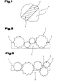
- Fig. 1 shows a friction member 1 with a first surface 2. On this surface 2, a functional surface 3 is formed, which is designed for frictional engagement with a second, not shown friction member. This functional surface is provided with a friction lining 4 or friction varnish.
- This friction lining 4 is in Fig. 2 better represented. It comprises a binder matrix 5, in which friction particles 6 are embedded in such a way that they project beyond a binder matrix surface 7.
- the friction particles 6 preferably have a Mohs hardness selected from a range having a lower limit of 8 and an upper limit of 10.
- friction particles 6 have to have approximately the same size, but it is possible to provide a spectrum or one or more sieve fractions at different diameters of the friction particles 6.
- the friction particles 6 have a non-elongated habit, that is, for example, are approximately round or bulbous, as in Fig. 2 you can see. It can thus be prevented that the friction particles 6 are embedded in the binder matrix 5 in a preferred orientation.
- the friction particles 6 have pronounced peaks and edges to increase the friction effect.
- Fig. 3 a variant of the friction lining 4 is shown.
- the friction particles 6 project on the one hand over the outer binder matrix surface 7 and over the lower, on the friction member 1 facing binder matrix surface 8.
- friction components 1 in the form of differential locks, dry or wet-running clutches, dry or wet-running brakes, multi-disc brakes, holding brakes, safety brakes were used with the friction lining 4 according to the invention in the form of synchronizer rings, brake disks, brake shoes, clutch disks or friction components 1 or hydrodynamic drives coated.
- the coating is carried out on the functional surfaces 3.
- a functional surface 3 in the context of the invention a surface of a friction member 1 is referred to, which is engageable with another friction member in frictional engagement and optionally positive engagement.
- wet applications are understood as meaning applications of the friction lining 4 in which the friction lining 4 is covered by a liquid, such as, for example, a brake fluid or fluid for an automatic transmission is wetted or impregnated during use. During use of the "wet” friction material, the fluid is squeezed out of the friction material.
- the friction lining 4 is suitable for "wet” applications, this should have a number of properties.
- the friction lining 4 should be resilient or resilient, but resistant to compressive stress, abrasion and stress, it should have a high heat resistance and be able to give off heat quickly. He should have a long-lasting, consistent and consistent friction behavior.
- the friction lining 4 according to the invention.
- corresponding synthetic resins are used as binders which have this elasticity after curing. Modification of the synthetic binders is possible, for example, by appropriately selecting the chain length and the number and type of side chains and functional group on the polymer threads of the synthetic resin, respectively. This has also been described many times in the literature, for example in “ Ullmann's Encyclopedia of Industrial Chemistry; Urban &Schwarzenberg; Kunststoff, 5th edition, 1997 ".
- the carrier of the friction lining 4 according to the invention is usually made of a metallic material. This can be produced both by a casting process, as well as formed as a sintered component. There are both carriers of pure metals, as well as alloys of several metals possible. Examples include steel, materials based on aluminum, iron, copper, magnesium. Examples of sintered metal alloys can be found in DIN V 30 910 Part 4, page 3.
- the functional surface 3 of a synchronizing ring made of steel was coated. This steel sheet serves as a support beam.
- a friction lining 4 was applied, consisting of 45 wt .-% phenolic resin as the binder matrix 5 and 55 wt .-% silicon carbide particles as friction particles. 6
- the phenolic resin was applied as a dispersion on thegnacs simulation.3.
- Ethanol was used as a solvent or dispersant in a proportion of 25% based on the phenol resin with solvent.
- solvents or dispersants may also be used, e.g. generally alcohols, butanone, xylene, or generally aromatic solvents.
- the proportion of the solvent may be between 15% and 40%, in particular between 20% and 30%, based on the phenolic resin with solvent.
- the silicon carbide particles were scattered on the phenol resin which had still hardened. Silicon carbide particles were used, of which 50% had a particle diameter of 40 ⁇ m. The phenolic resin was applied in a layer thickness of 20 microns.
- the phenolic resin was cured at a temperature of 220 ° C, thereby embedding the silicon carbide particles in the phenolic resin matrix.
- the friction lining 4 thus produced shows very good friction properties and low noise.
- a pressure was exerted on the friction lining 4 before solidification of the phenolic resin matrix, whereby the silicon carbide particles were pressed into the matrix. It was thus possible to achieve an improvement in the thermal conductivity and, in addition, better delamination properties could be detected.
- the pressure on the friction lining was maintained for a period of 15 seconds to 30 seconds after heating to 250 ° C. A pressure of 15 N / mm 2 was used.
- the synchronizer ring can be coated, for example, in a corresponding form via a spray nozzle with the phenolic resin and the silicon carbide particles are sprinkled in the still open mold on the phenolic resin. After closing the mold, both the elevated temperature and the pressure are made available via this.
- an adhesion promoter was applied to the functional surface before the application of the phenolic resin to increase the adhesive strength - in the context of the invention is not mandatory.
- the adhesion promoter used was a so-called phenolic resin-based primer (dilute phenolic resin).
- phenolic resin-based primer dilute phenolic resin
- the surface can also be pretreated by grinding.
- the mechanical surface treatment it is also possible to perform a chemical surface treatment, for example, to etch the surface, the Etching naturally depends on the material used for the carrier material. It is also possible to phosphatize the surface or activate the surface in the plasma.
- a friction lining 4 based on phenolic resin of the above composition was produced on a clutch disk of a sintered material "Sint D11" (according to DIN 30910-4). Again, pressure was applied to the silicon carbide particles to obtain a mechanical entanglement with the sintered material.
- This embodiment has a significantly higher adhesion of the friction lining 4 on the surface of the sintered component.
- Embodiments 1 to 5 were repeated, replacing the phenol resin with a polyamideimide resin.
- the proportion of the polyamideimide resin on the friction lining 4 was 55%.
- the friction lining 4 it is also possible in addition to the previously mentioned Aufstreu method to produce a dispersion of the polymerizable synthetic binder and the friction particles contained therein 6 and apply this dispersion directly on the functional surface 3 of the corresponding friction member 1.
- This dispersion can for example be brushed on, rolled, printed or sprayed.
- Corresponding printing methods such as e.g. HVLP processes (high volume low pressure), screen printing processes, are already known from the prior art.
- the resins used are preferably thermosetting.
- the friction particles 6 used have an average diameter which is chosen so large that at least a portion of these friction particles 6 protrude beyond the binder matrix by a height which is selected from a range with a lower limit of 0, 5 microns and an upper limit of 70 microns.
- these particles have an average diameter which is dimensioned such that this height has a value which is selected from a range with a lower limit of 3 ⁇ m and an upper limit of 30 ⁇ m.
- the particles have an average diameter dimensioned such that this height has a value selected from a range with a lower limit of 0.5 ⁇ m and an upper limit of 10 ⁇ m.
- these values mainly apply to the projection of the friction particles 6 on the outer surface of the friction component 1, that is to say the surface which can be brought into frictional engagement with a further friction component.
- these friction particles may have a projection with respect to the binder matrix 5 whose height assumes a value selected from a region with a lower limit of 0, 1 ⁇ m and an upper limit of 5 ⁇ m, in particular selected from a range with a lower limit of 0.1 ⁇ m and an upper limit of 2 ⁇ m.
- the friction lining 4 according to the invention can withstand surface pressures of up to about 100 bar, even if this friction lining 4 is used under limited lubrication conditions.
- the friction lining 4 according to the invention also achieves a relatively constant friction during the engagement or disengagement of the components of, for example, the transmission and the brake system. It can thus be achieved a constant power transmission.
- the friction material further has a good shear strength, whereby the friction member 1 itself resists delamination during use as much as possible.
- the friction lining 4 can be used on the thread of a screw or the internal thread of a screw receiving bore to secure the screw.
- this friction lining 4 can be applied directly to at least a portion of the thread of the screw or the thread of the screw seat.
- 4 screw connections are secured with the friction lining according to the invention, which usually hitherto by additional securing means, such as pin pins, circlips, or adhesives, which are applied to the thread, must be secured to prevent, for example, the loosening of the screw due to vibration.
- the friction lining 4 this not only has the advantage of a higher security is given to the screw, but the threaded connection can also be repeatedly solved and tightened again without - as is the case with adhesives - the friction lining 4 after the one-off Loosening would have to be reapplied. It can thus be avoided additional steps in the assembly, for example, for attaching the split pins or circlips.
Landscapes
- Engineering & Computer Science (AREA)
- General Engineering & Computer Science (AREA)
- Mechanical Engineering (AREA)
- Braking Arrangements (AREA)
- Mechanical Operated Clutches (AREA)
- Manufacture Of Macromolecular Shaped Articles (AREA)
Applications Claiming Priority (1)
| Application Number | Priority Date | Filing Date | Title |
|---|---|---|---|
| ATA211/2007A AT504820B1 (de) | 2007-02-09 | 2007-02-09 | Reibbelag |
Publications (3)
| Publication Number | Publication Date |
|---|---|
| EP1959152A2 true EP1959152A2 (fr) | 2008-08-20 |
| EP1959152A3 EP1959152A3 (fr) | 2011-05-18 |
| EP1959152B1 EP1959152B1 (fr) | 2016-11-16 |
Family
ID=39563537
Family Applications (1)
| Application Number | Title | Priority Date | Filing Date |
|---|---|---|---|
| EP08002097.7A Not-in-force EP1959152B1 (fr) | 2007-02-09 | 2008-02-05 | Garniture de friction |
Country Status (3)
| Country | Link |
|---|---|
| US (1) | US8025134B2 (fr) |
| EP (1) | EP1959152B1 (fr) |
| AT (1) | AT504820B1 (fr) |
Cited By (7)
| Publication number | Priority date | Publication date | Assignee | Title |
|---|---|---|---|---|
| DE102009023402A1 (de) | 2009-05-29 | 2010-12-02 | Esk Ceramics Gmbh & Co. Kg | Suspension zur Herstellung einer reibwerterhöhenden Schicht, Formkörper mit einer solchen reibwerterhöhenden Schicht, Verfahren zu dessen Herstellung und dessen Verwendung |
| DE102010014957A1 (de) | 2010-04-14 | 2011-12-01 | Volkswagen Ag | Reibvorrichtung |
| EP2540781A1 (fr) * | 2011-06-29 | 2013-01-02 | Raimund Beck Nageltechnik GmbH | Moyen de fixation doté d'un revêtement contenant un corps de remplissage |
| US8894333B2 (en) | 2012-11-13 | 2014-11-25 | Raimund Beck Nageltechnik Gmbh | Fastening means with a coating containing filling material |
| US9291202B2 (en) | 2010-12-07 | 2016-03-22 | Aktiebolaget Skf | Friction-enhancing lacquer and machine part coated therewith |
| DE102015220169A1 (de) * | 2015-10-16 | 2017-04-20 | Bayerische Motoren Werke Aktiengesellschaft | Folie zur Reibungserhöhung zwischen zwei kraftschlüssig verbundenen Bauteilen |
| EP3366509A1 (fr) * | 2017-02-23 | 2018-08-29 | Adient Engineering and IP GmbH | Système de rail pour un dispositif de réglage en longueur et siège de véhicule |
Families Citing this family (24)
| Publication number | Priority date | Publication date | Assignee | Title |
|---|---|---|---|---|
| DE102007024170A1 (de) * | 2007-05-24 | 2008-11-27 | Andreas Stihl Ag & Co. Kg | Handgeführtes Arbeitsgerät und Verfahren zur Herstellung einer Bremseinrichtung eines handgeführten Arbeitsgeräts |
| DE102007057906B4 (de) * | 2007-11-29 | 2015-10-22 | Ab Skf | Beschichtungsanordnung |
| SE532159C2 (sv) * | 2008-03-12 | 2009-11-03 | Skf Ab | En monteringshylsa för montering av en ring på en axel och en lagerenhet innefattande en sådan monteringshylsa |
| DE102008021636B3 (de) * | 2008-04-30 | 2009-11-19 | Esk Ceramics Gmbh & Co. Kg | Verfahren zum Fixieren eines Verbindungselements auf einem Werkstück und Bauteil aus einem Werkstück mit einem darauf fixierten Verbindungselement |
| DE102009030506A1 (de) * | 2008-06-30 | 2009-12-31 | Borgwarner Inc., Auburn Hills | Reibungsmaterialien |
| JP5567774B2 (ja) * | 2008-10-10 | 2014-08-06 | トヨタ自動車株式会社 | 摩擦対 |
| DE102009007993A1 (de) * | 2009-02-07 | 2010-10-21 | Ab Skf | Verbindung |
| DE102009007992A1 (de) * | 2009-02-07 | 2010-08-19 | Ab Skf | Beschichtungsanordnung |
| WO2013179423A1 (fr) * | 2012-05-30 | 2013-12-05 | 三菱電機株式会社 | Base de machine de levage d'ascenseur et dispositif d'ascenseur |
| EP2781784A1 (fr) * | 2013-03-21 | 2014-09-24 | Brembo SGL Carbon Ceramic Brakes GmbH | Disques de frein renforcés avec des fibres de carbone |
| WO2014176301A1 (fr) * | 2013-04-25 | 2014-10-30 | Schaeffler Technologies Gmbh & Co. Kg | Rondelle de butée incluant un matériau de friction humide avec une surface revêtue de résine |
| DE102015204813B4 (de) | 2014-03-26 | 2019-05-02 | Ford Global Technologies, Llc | Verfahren zur Herstellung einer Bremsscheibe sowie Bremsscheibe |
| KR102433048B1 (ko) * | 2014-04-01 | 2022-08-18 | 섀플러 테크놀로지스 아게 운트 코. 카게 | 에칭된 클러치 표면을 구비한 토크 컨버터의 제조 방법 및 에칭된 클러치 표면을 구비한 토크 컨버터 |
| DE102014007103A1 (de) * | 2014-05-15 | 2015-11-19 | GM Global Technology Operations LLC (n. d. Ges. d. Staates Delaware) | Reibschlüssige Befestigung eines ersten Bauteils an einem zweiten Bauteil |
| CN107208677A (zh) * | 2015-02-18 | 2017-09-26 | 宝马股份公司 | 车辆行走机构区域中在可分离地彼此夹紧的接合匹配件之间的连接系统 |
| DE102015108770A1 (de) | 2015-06-03 | 2016-12-08 | Tmd Friction Services Gmbh | Verfahren zur Besandung von Trommelbremsbelägen |
| US9771994B2 (en) * | 2015-11-06 | 2017-09-26 | Schaeffler Technologies AG & Co. KG | Wet friction materials including cristobalite as filler material |
| JP6719312B2 (ja) * | 2016-07-15 | 2020-07-08 | 株式会社キトー | ブレーキ付モータおよびブレーキ付モータの製造方法 |
| DE102017203561A1 (de) | 2017-03-06 | 2018-09-06 | Siemens Aktiengesellschaft | Drehmomente übertragende Reibscheibe mit Nasen, Verbindung und Verfahren zur Herstellung |
| US10584740B2 (en) * | 2018-02-12 | 2020-03-10 | Schaeffler Technologies AG & Co. KG | Thrust bushing surface layer using directly bonded heat activated nitrile-phenolic adhesive film |
| DE102018116192A1 (de) * | 2018-07-04 | 2020-01-09 | Westfalia-Automotive Gmbh | Zugfahrzeugkupplung-Sensorvorrichtung mit reibschlüssigem Mitnehmer |
| EP3742002A1 (fr) * | 2019-05-24 | 2020-11-25 | 3M Innovative Properties Company | Élément de connexion augmentant la friction de connexion des composants, procédé de fabrication d'un élément de connexion et utilisation d'un élément de connexion |
| US11541516B2 (en) * | 2019-09-25 | 2023-01-03 | Snap-On Incorporated | Fastener retention and anti-camout tool bit |
| CN114294360A (zh) * | 2021-12-31 | 2022-04-08 | 青岛方冠摩擦材料有限公司 | 一种新型低膨胀率金属纤维增强树脂基刹车片混合材料 |
Citations (3)
| Publication number | Priority date | Publication date | Assignee | Title |
|---|---|---|---|---|
| AT387395B (de) | 1987-02-25 | 1989-01-10 | Miba Sintermetall Ag | Verfahren zum beschichten eines stuetztraegers mit einem kunstharzgebundenen reibbelag |
| DE69831821T2 (de) | 1997-01-16 | 2006-05-18 | Borgwarner Inc., Auburn Hills | Hochleitungs-zweischichtigesreibungsmaterial |
| DE60210953T2 (de) | 2002-08-30 | 2006-09-21 | Borgwarner Inc., Auburn Hills | Reibungsmaterial mit Reibungsveränderungsschicht |
Family Cites Families (23)
| Publication number | Priority date | Publication date | Assignee | Title |
|---|---|---|---|---|
| US1955572A (en) * | 1932-08-06 | 1934-04-17 | Silk City Metals Coating Compa | Art of metal coating bodies |
| US2281558A (en) * | 1933-03-06 | 1942-05-05 | Minnesota Mining & Mfg | Manufacture of abrasive articles and apparatus therefor |
| US2225877A (en) * | 1939-09-22 | 1940-12-24 | Carborundum Co | Method and apparatus for manufacturing granular coated webs |
| US2322156A (en) * | 1941-12-30 | 1943-06-15 | Behr Manning Corp | Coated abrasive |
| US2411867A (en) * | 1942-12-19 | 1946-12-03 | Brenner Bert | Industrial diamond tool and method of producing same |
| US3048482A (en) * | 1958-10-22 | 1962-08-07 | Rexall Drug Co | Abrasive articles and methods of making the same |
| US3117845A (en) * | 1960-04-27 | 1964-01-14 | Bendix Corp | Friction coated metal base |
| US3508890A (en) * | 1968-01-02 | 1970-04-28 | Gen Electric | Coated abrasive articles having plural metal coatings |
| US3692341A (en) * | 1970-03-02 | 1972-09-19 | Kenneth G Wynne Brown | Bolted-up friction joints in structural steel-work |
| DE7009386U (de) * | 1970-03-14 | 1972-09-07 | Scharf Gmbh Maschf | Bremsbacke aus stahl fuer sicherheitsbremsvorrichtungen bei schienengebundenen bergbaufoerdermitteln, insbesondere haenge- und standbahnen. |
| CH542274A (de) * | 1970-10-30 | 1973-09-30 | Luethy Erich | Pedal für Fahrzeuge |
| CA1032792A (fr) * | 1974-07-15 | 1978-06-13 | Donald R. Wesner | Revetement modificateur de couple pour organes de liaison filetes |
| DE2832609C2 (de) * | 1978-07-22 | 1983-08-11 | Heinrich H. Klüssendorf GmbH & Co KG, 1000 Berlin | Platte aus elastischem Material |
| US4662972A (en) * | 1984-02-16 | 1987-05-05 | Thompson Thomas L | Method of forming a non-skid surfaced structure |
| DE3907443C2 (de) * | 1989-03-08 | 1994-02-24 | Miba Frictec Gmbh | Verfahren und Vorrichtung zum Herstellen einer Reiblamelle |
| US5083650A (en) * | 1991-05-24 | 1992-01-28 | Minnesota Mining And Manufacturing Company | Friction material having heat-resistant paper support bearing resin-bonded carbon particles |
| DE4121839C2 (de) | 1991-07-02 | 2003-01-09 | Werner Hermann Wera Werke | Werkzeug mit drehmomentübertragenden Arbeitsflächen und Verfahren zur Herstellung desselben |
| US5856244A (en) * | 1993-08-04 | 1999-01-05 | Borg-Warner Automotive, Inc. | Carbon deposit friction lining material |
| DE29521198U1 (de) * | 1995-08-23 | 1996-12-19 | Sintermetallwerk Krebsöge GmbH, 42477 Radevormwald | Bauteil mit einer zumindest in Teilbereichen seiner Oberfläche erhöhten Rauheit für eine Preßverbindung mit einem Bauelement |
| US6182804B1 (en) | 1997-01-16 | 2001-02-06 | Borgwarner, Inc. | High performance two-ply friction material |
| DE19823928A1 (de) * | 1998-05-28 | 1999-12-09 | Kempten Elektroschmelz Gmbh | Verbindungselement zur kraftschlüssigen Verbindung von Bauteilen |
| US6347905B1 (en) | 1998-05-28 | 2002-02-19 | Elektroschmelzwerk Kempten Gmbh | Connecting element for the frictional connection of components |
| DE10148831A1 (de) * | 2001-10-04 | 2003-04-24 | Wacker Chemie Gmbh | Kraftübertragende Oberflächenschicht und Verfahren zu ihrer Herstellung |
-
2007
- 2007-02-09 AT ATA211/2007A patent/AT504820B1/de not_active IP Right Cessation
-
2008
- 2008-02-05 EP EP08002097.7A patent/EP1959152B1/fr not_active Not-in-force
- 2008-02-06 US US12/012,955 patent/US8025134B2/en not_active Expired - Fee Related
Patent Citations (3)
| Publication number | Priority date | Publication date | Assignee | Title |
|---|---|---|---|---|
| AT387395B (de) | 1987-02-25 | 1989-01-10 | Miba Sintermetall Ag | Verfahren zum beschichten eines stuetztraegers mit einem kunstharzgebundenen reibbelag |
| DE69831821T2 (de) | 1997-01-16 | 2006-05-18 | Borgwarner Inc., Auburn Hills | Hochleitungs-zweischichtigesreibungsmaterial |
| DE60210953T2 (de) | 2002-08-30 | 2006-09-21 | Borgwarner Inc., Auburn Hills | Reibungsmaterial mit Reibungsveränderungsschicht |
Cited By (8)
| Publication number | Priority date | Publication date | Assignee | Title |
|---|---|---|---|---|
| DE102009023402A1 (de) | 2009-05-29 | 2010-12-02 | Esk Ceramics Gmbh & Co. Kg | Suspension zur Herstellung einer reibwerterhöhenden Schicht, Formkörper mit einer solchen reibwerterhöhenden Schicht, Verfahren zu dessen Herstellung und dessen Verwendung |
| DE102010014957A1 (de) | 2010-04-14 | 2011-12-01 | Volkswagen Ag | Reibvorrichtung |
| US9291202B2 (en) | 2010-12-07 | 2016-03-22 | Aktiebolaget Skf | Friction-enhancing lacquer and machine part coated therewith |
| EP2540781A1 (fr) * | 2011-06-29 | 2013-01-02 | Raimund Beck Nageltechnik GmbH | Moyen de fixation doté d'un revêtement contenant un corps de remplissage |
| US8894333B2 (en) | 2012-11-13 | 2014-11-25 | Raimund Beck Nageltechnik Gmbh | Fastening means with a coating containing filling material |
| DE102015220169A1 (de) * | 2015-10-16 | 2017-04-20 | Bayerische Motoren Werke Aktiengesellschaft | Folie zur Reibungserhöhung zwischen zwei kraftschlüssig verbundenen Bauteilen |
| US10968928B2 (en) | 2015-10-16 | 2021-04-06 | Bayerische Motoren Werke Aktiengesellschaft | Film for increasing friction between two frictionally connected components |
| EP3366509A1 (fr) * | 2017-02-23 | 2018-08-29 | Adient Engineering and IP GmbH | Système de rail pour un dispositif de réglage en longueur et siège de véhicule |
Also Published As
| Publication number | Publication date |
|---|---|
| AT504820A1 (de) | 2008-08-15 |
| US8025134B2 (en) | 2011-09-27 |
| AT504820B1 (de) | 2012-10-15 |
| EP1959152B1 (fr) | 2016-11-16 |
| US20080308365A1 (en) | 2008-12-18 |
| EP1959152A3 (fr) | 2011-05-18 |
Similar Documents
| Publication | Publication Date | Title |
|---|---|---|
| EP1959152B1 (fr) | Garniture de friction | |
| EP2670999B1 (fr) | Matière anti-friction | |
| DE60309396T2 (de) | Reibmaterial mit Reibungsmodifizierungsschicht, die symmetrische geometrische Formen aufweist | |
| DE60221006T2 (de) | Reibungsmaterial mit Nanopartikel enthaltender Reibungsveräanderungsschicht | |
| DE102009042621B4 (de) | Reibmaterial für ein Reibelement eines Drehmoment übertragenden Mechanismus | |
| EP2435724A1 (fr) | Suspension pour la fabrication d'une couche augmentant le coefficient de friction, corps moulé pourvu de ladite couche augmentant le coefficient de friction, son procédé de fabrication et son utilisation | |
| EP2848824B1 (fr) | Feuille augmentant la friction | |
| EP3938673B1 (fr) | Assemblage de friction | |
| DE69005791T2 (de) | Nassreibungsmaterial. | |
| EP3816471B1 (fr) | Insert d'augmentation de friction pour les composants à liaison par complémentarité de force, procédé de fabrication d'un insert d'augmentation de friction et procédé de fabrication d'un emmanchement à force | |
| AT504336B1 (de) | Kettenrad | |
| DE10338199B4 (de) | Kupplungsbeläge aus faserverstärkten keramischen Werkstoffen | |
| EP3708276B1 (fr) | Doublure de friction | |
| EP2012038B1 (fr) | Garniture de friction fonctionnant à sec | |
| EP2458241B1 (fr) | Procédé de fabrication d'un élément de friction | |
| EP3137785A1 (fr) | Garniture de friction pour freins industriels et éléments d'entraînement, et procédé de fabrication d'une garniture de friction pour freins industriels et éléments d'entraînement | |
| DE19946706C2 (de) | Reibbelag | |
| DE102010020001A1 (de) | Reibbelag zur Drehmomentübertragung | |
| WO2008009261A1 (fr) | Système de friction | |
| EP2053265B1 (fr) | Dispositif de frein pour un véhicule automobile | |
| DE102018205761B4 (de) | Verfahren zur Herstellung eines Reibmaterials, hierdurch hergestelltes Reibmaterial und dessen Verwendung | |
| DE102008039029A1 (de) | Reibbelag | |
| DE102007047015A1 (de) | Beschichtetes Bauteil und Verfahren zur Herstellung eines solchen Bauteils |
Legal Events
| Date | Code | Title | Description |
|---|---|---|---|
| PUAI | Public reference made under article 153(3) epc to a published international application that has entered the european phase |
Free format text: ORIGINAL CODE: 0009012 |
|
| AK | Designated contracting states |
Kind code of ref document: A2 Designated state(s): AT BE BG CH CY CZ DE DK EE ES FI FR GB GR HR HU IE IS IT LI LT LU LV MC MT NL NO PL PT RO SE SI SK TR |
|
| AX | Request for extension of the european patent |
Extension state: AL BA MK RS |
|
| PUAL | Search report despatched |
Free format text: ORIGINAL CODE: 0009013 |
|
| AK | Designated contracting states |
Kind code of ref document: A3 Designated state(s): AT BE BG CH CY CZ DE DK EE ES FI FR GB GR HR HU IE IS IT LI LT LU LV MC MT NL NO PL PT RO SE SI SK TR |
|
| AX | Request for extension of the european patent |
Extension state: AL BA MK RS |
|
| 17P | Request for examination filed |
Effective date: 20110711 |
|
| AKX | Designation fees paid |
Designated state(s): AT BE BG CH CY CZ DE DK EE ES FI FR GB GR HR HU IE IS IT LI LT LU LV MC MT NL NO PL PT RO SE SI SK TR |
|
| 17Q | First examination report despatched |
Effective date: 20140310 |
|
| GRAP | Despatch of communication of intention to grant a patent |
Free format text: ORIGINAL CODE: EPIDOSNIGR1 |
|
| INTG | Intention to grant announced |
Effective date: 20160608 |
|
| GRAS | Grant fee paid |
Free format text: ORIGINAL CODE: EPIDOSNIGR3 |
|
| GRAA | (expected) grant |
Free format text: ORIGINAL CODE: 0009210 |
|
| AK | Designated contracting states |
Kind code of ref document: B1 Designated state(s): AT BE BG CH CY CZ DE DK EE ES FI FR GB GR HR HU IE IS IT LI LT LU LV MC MT NL NO PL PT RO SE SI SK TR |
|
| REG | Reference to a national code |
Ref country code: GB Ref legal event code: FG4D Free format text: NOT ENGLISH |
|
| RIN1 | Information on inventor provided before grant (corrected) |
Inventor name: FOEGE, VOLKER DIPL.-ING. Inventor name: TSIOPTSIAS, ZISIS |
|
| REG | Reference to a national code |
Ref country code: CH Ref legal event code: EP Ref country code: DE Ref legal event code: R082 Ref document number: 502008014794 Country of ref document: DE Representative=s name: ANWAELTE BURGER UND PARTNER RECHTSANWALT GMBH, AT Ref country code: DE Ref legal event code: R082 Ref document number: 502008014794 Country of ref document: DE Representative=s name: ABP BURGER RECHTSANWALTSGESELLSCHAFT MBH, DE |
|
| REG | Reference to a national code |
Ref country code: IE Ref legal event code: FG4D Free format text: LANGUAGE OF EP DOCUMENT: GERMAN |
|
| REG | Reference to a national code |
Ref country code: AT Ref legal event code: REF Ref document number: 846247 Country of ref document: AT Kind code of ref document: T Effective date: 20161215 |
|
| REG | Reference to a national code |
Ref country code: DE Ref legal event code: R096 Ref document number: 502008014794 Country of ref document: DE |
|
| REG | Reference to a national code |
Ref country code: DE Ref legal event code: R096 Ref document number: 502008014794 Country of ref document: DE |
|
| PG25 | Lapsed in a contracting state [announced via postgrant information from national office to epo] |
Ref country code: LV Free format text: LAPSE BECAUSE OF FAILURE TO SUBMIT A TRANSLATION OF THE DESCRIPTION OR TO PAY THE FEE WITHIN THE PRESCRIBED TIME-LIMIT Effective date: 20161116 |
|
| REG | Reference to a national code |
Ref country code: NL Ref legal event code: MP Effective date: 20161116 |
|
| REG | Reference to a national code |
Ref country code: LT Ref legal event code: MG4D |
|
| PG25 | Lapsed in a contracting state [announced via postgrant information from national office to epo] |
Ref country code: GR Free format text: LAPSE BECAUSE OF FAILURE TO SUBMIT A TRANSLATION OF THE DESCRIPTION OR TO PAY THE FEE WITHIN THE PRESCRIBED TIME-LIMIT Effective date: 20170217 Ref country code: LT Free format text: LAPSE BECAUSE OF FAILURE TO SUBMIT A TRANSLATION OF THE DESCRIPTION OR TO PAY THE FEE WITHIN THE PRESCRIBED TIME-LIMIT Effective date: 20161116 Ref country code: NO Free format text: LAPSE BECAUSE OF FAILURE TO SUBMIT A TRANSLATION OF THE DESCRIPTION OR TO PAY THE FEE WITHIN THE PRESCRIBED TIME-LIMIT Effective date: 20170216 Ref country code: NL Free format text: LAPSE BECAUSE OF FAILURE TO SUBMIT A TRANSLATION OF THE DESCRIPTION OR TO PAY THE FEE WITHIN THE PRESCRIBED TIME-LIMIT Effective date: 20161116 Ref country code: SE Free format text: LAPSE BECAUSE OF FAILURE TO SUBMIT A TRANSLATION OF THE DESCRIPTION OR TO PAY THE FEE WITHIN THE PRESCRIBED TIME-LIMIT Effective date: 20161116 |
|
| PG25 | Lapsed in a contracting state [announced via postgrant information from national office to epo] |
Ref country code: BE Free format text: LAPSE BECAUSE OF NON-PAYMENT OF DUE FEES Effective date: 20170228 Ref country code: PL Free format text: LAPSE BECAUSE OF FAILURE TO SUBMIT A TRANSLATION OF THE DESCRIPTION OR TO PAY THE FEE WITHIN THE PRESCRIBED TIME-LIMIT Effective date: 20161116 Ref country code: FI Free format text: LAPSE BECAUSE OF FAILURE TO SUBMIT A TRANSLATION OF THE DESCRIPTION OR TO PAY THE FEE WITHIN THE PRESCRIBED TIME-LIMIT Effective date: 20161116 Ref country code: HR Free format text: LAPSE BECAUSE OF FAILURE TO SUBMIT A TRANSLATION OF THE DESCRIPTION OR TO PAY THE FEE WITHIN THE PRESCRIBED TIME-LIMIT Effective date: 20161116 Ref country code: PT Free format text: LAPSE BECAUSE OF FAILURE TO SUBMIT A TRANSLATION OF THE DESCRIPTION OR TO PAY THE FEE WITHIN THE PRESCRIBED TIME-LIMIT Effective date: 20170316 Ref country code: ES Free format text: LAPSE BECAUSE OF FAILURE TO SUBMIT A TRANSLATION OF THE DESCRIPTION OR TO PAY THE FEE WITHIN THE PRESCRIBED TIME-LIMIT Effective date: 20161116 |
|
| PG25 | Lapsed in a contracting state [announced via postgrant information from national office to epo] |
Ref country code: SK Free format text: LAPSE BECAUSE OF FAILURE TO SUBMIT A TRANSLATION OF THE DESCRIPTION OR TO PAY THE FEE WITHIN THE PRESCRIBED TIME-LIMIT Effective date: 20161116 Ref country code: RO Free format text: LAPSE BECAUSE OF FAILURE TO SUBMIT A TRANSLATION OF THE DESCRIPTION OR TO PAY THE FEE WITHIN THE PRESCRIBED TIME-LIMIT Effective date: 20161116 Ref country code: EE Free format text: LAPSE BECAUSE OF FAILURE TO SUBMIT A TRANSLATION OF THE DESCRIPTION OR TO PAY THE FEE WITHIN THE PRESCRIBED TIME-LIMIT Effective date: 20161116 Ref country code: DK Free format text: LAPSE BECAUSE OF FAILURE TO SUBMIT A TRANSLATION OF THE DESCRIPTION OR TO PAY THE FEE WITHIN THE PRESCRIBED TIME-LIMIT Effective date: 20161116 Ref country code: CZ Free format text: LAPSE BECAUSE OF FAILURE TO SUBMIT A TRANSLATION OF THE DESCRIPTION OR TO PAY THE FEE WITHIN THE PRESCRIBED TIME-LIMIT Effective date: 20161116 |
|
| REG | Reference to a national code |
Ref country code: DE Ref legal event code: R097 Ref document number: 502008014794 Country of ref document: DE |
|
| PG25 | Lapsed in a contracting state [announced via postgrant information from national office to epo] |
Ref country code: BG Free format text: LAPSE BECAUSE OF FAILURE TO SUBMIT A TRANSLATION OF THE DESCRIPTION OR TO PAY THE FEE WITHIN THE PRESCRIBED TIME-LIMIT Effective date: 20170216 Ref country code: IT Free format text: LAPSE BECAUSE OF FAILURE TO SUBMIT A TRANSLATION OF THE DESCRIPTION OR TO PAY THE FEE WITHIN THE PRESCRIBED TIME-LIMIT Effective date: 20161116 |
|
| PLBE | No opposition filed within time limit |
Free format text: ORIGINAL CODE: 0009261 |
|
| STAA | Information on the status of an ep patent application or granted ep patent |
Free format text: STATUS: NO OPPOSITION FILED WITHIN TIME LIMIT |
|
| PG25 | Lapsed in a contracting state [announced via postgrant information from national office to epo] |
Ref country code: MC Free format text: LAPSE BECAUSE OF FAILURE TO SUBMIT A TRANSLATION OF THE DESCRIPTION OR TO PAY THE FEE WITHIN THE PRESCRIBED TIME-LIMIT Effective date: 20161116 |
|
| REG | Reference to a national code |
Ref country code: CH Ref legal event code: PL |
|
| 26N | No opposition filed |
Effective date: 20170817 |
|
| PG25 | Lapsed in a contracting state [announced via postgrant information from national office to epo] |
Ref country code: LI Free format text: LAPSE BECAUSE OF NON-PAYMENT OF DUE FEES Effective date: 20170228 Ref country code: CH Free format text: LAPSE BECAUSE OF NON-PAYMENT OF DUE FEES Effective date: 20170228 |
|
| REG | Reference to a national code |
Ref country code: IE Ref legal event code: MM4A |
|
| PG25 | Lapsed in a contracting state [announced via postgrant information from national office to epo] |
Ref country code: SI Free format text: LAPSE BECAUSE OF FAILURE TO SUBMIT A TRANSLATION OF THE DESCRIPTION OR TO PAY THE FEE WITHIN THE PRESCRIBED TIME-LIMIT Effective date: 20161116 |
|
| REG | Reference to a national code |
Ref country code: FR Ref legal event code: ST Effective date: 20171031 |
|
| PG25 | Lapsed in a contracting state [announced via postgrant information from national office to epo] |
Ref country code: LU Free format text: LAPSE BECAUSE OF NON-PAYMENT OF DUE FEES Effective date: 20170205 |
|
| PG25 | Lapsed in a contracting state [announced via postgrant information from national office to epo] |
Ref country code: FR Free format text: LAPSE BECAUSE OF NON-PAYMENT OF DUE FEES Effective date: 20170228 |
|
| REG | Reference to a national code |
Ref country code: BE Ref legal event code: MM Effective date: 20170228 |
|
| PG25 | Lapsed in a contracting state [announced via postgrant information from national office to epo] |
Ref country code: IE Free format text: LAPSE BECAUSE OF NON-PAYMENT OF DUE FEES Effective date: 20170205 |
|
| REG | Reference to a national code |
Ref country code: AT Ref legal event code: MM01 Ref document number: 846247 Country of ref document: AT Kind code of ref document: T Effective date: 20170205 |
|
| PGFP | Annual fee paid to national office [announced via postgrant information from national office to epo] |
Ref country code: DE Payment date: 20180205 Year of fee payment: 11 Ref country code: GB Payment date: 20180205 Year of fee payment: 11 |
|
| PG25 | Lapsed in a contracting state [announced via postgrant information from national office to epo] |
Ref country code: AT Free format text: LAPSE BECAUSE OF NON-PAYMENT OF DUE FEES Effective date: 20170205 |
|
| REG | Reference to a national code |
Ref country code: DE Ref legal event code: R082 Ref document number: 502008014794 Country of ref document: DE Representative=s name: ABP BURGER RECHTSANWALTSGESELLSCHAFT MBH, DE |
|
| PG25 | Lapsed in a contracting state [announced via postgrant information from national office to epo] |
Ref country code: MT Free format text: LAPSE BECAUSE OF FAILURE TO SUBMIT A TRANSLATION OF THE DESCRIPTION OR TO PAY THE FEE WITHIN THE PRESCRIBED TIME-LIMIT Effective date: 20161116 |
|
| PG25 | Lapsed in a contracting state [announced via postgrant information from national office to epo] |
Ref country code: HU Free format text: LAPSE BECAUSE OF FAILURE TO SUBMIT A TRANSLATION OF THE DESCRIPTION OR TO PAY THE FEE WITHIN THE PRESCRIBED TIME-LIMIT; INVALID AB INITIO Effective date: 20080205 |
|
| REG | Reference to a national code |
Ref country code: DE Ref legal event code: R119 Ref document number: 502008014794 Country of ref document: DE |
|
| GBPC | Gb: european patent ceased through non-payment of renewal fee |
Effective date: 20190205 |
|
| PG25 | Lapsed in a contracting state [announced via postgrant information from national office to epo] |
Ref country code: CY Free format text: LAPSE BECAUSE OF NON-PAYMENT OF DUE FEES Effective date: 20161116 |
|
| PG25 | Lapsed in a contracting state [announced via postgrant information from national office to epo] |
Ref country code: DE Free format text: LAPSE BECAUSE OF NON-PAYMENT OF DUE FEES Effective date: 20190903 Ref country code: GB Free format text: LAPSE BECAUSE OF NON-PAYMENT OF DUE FEES Effective date: 20190205 |
|
| PG25 | Lapsed in a contracting state [announced via postgrant information from national office to epo] |
Ref country code: TR Free format text: LAPSE BECAUSE OF FAILURE TO SUBMIT A TRANSLATION OF THE DESCRIPTION OR TO PAY THE FEE WITHIN THE PRESCRIBED TIME-LIMIT Effective date: 20161116 |
|
| PG25 | Lapsed in a contracting state [announced via postgrant information from national office to epo] |
Ref country code: IS Free format text: LAPSE BECAUSE OF FAILURE TO SUBMIT A TRANSLATION OF THE DESCRIPTION OR TO PAY THE FEE WITHIN THE PRESCRIBED TIME-LIMIT Effective date: 20170316 |