EP1959155A1 - Verfahren zur Vernichtung von Stossbelastungen hydraulischer Stoßdämpfer - Google Patents
Verfahren zur Vernichtung von Stossbelastungen hydraulischer Stoßdämpfer Download PDFInfo
- Publication number
- EP1959155A1 EP1959155A1 EP07003045A EP07003045A EP1959155A1 EP 1959155 A1 EP1959155 A1 EP 1959155A1 EP 07003045 A EP07003045 A EP 07003045A EP 07003045 A EP07003045 A EP 07003045A EP 1959155 A1 EP1959155 A1 EP 1959155A1
- Authority
- EP
- European Patent Office
- Prior art keywords
- piston
- damping force
- piston velocity
- damper
- comfort
- Prior art date
- Legal status (The legal status is an assumption and is not a legal conclusion. Google has not performed a legal analysis and makes no representation as to the accuracy of the status listed.)
- Granted
Links
Images


Classifications
-
- B—PERFORMING OPERATIONS; TRANSPORTING
- B60—VEHICLES IN GENERAL
- B60G—VEHICLE SUSPENSION ARRANGEMENTS
- B60G13/00—Resilient suspensions characterised by arrangement, location or type of vibration dampers
- B60G13/02—Resilient suspensions characterised by arrangement, location or type of vibration dampers having dampers dissipating energy, e.g. frictionally
- B60G13/06—Resilient suspensions characterised by arrangement, location or type of vibration dampers having dampers dissipating energy, e.g. frictionally of fluid type
- B60G13/08—Resilient suspensions characterised by arrangement, location or type of vibration dampers having dampers dissipating energy, e.g. frictionally of fluid type hydraulic
-
- B—PERFORMING OPERATIONS; TRANSPORTING
- B60—VEHICLES IN GENERAL
- B60G—VEHICLE SUSPENSION ARRANGEMENTS
- B60G17/00—Resilient suspensions having means for adjusting the spring or vibration-damper characteristics, for regulating the distance between a supporting surface and a sprung part of vehicle or for locking suspension during use to meet varying vehicular or surface conditions, e.g. due to speed or load
- B60G17/06—Characteristics of dampers, e.g. mechanical dampers
- B60G17/08—Characteristics of fluid dampers
-
- F—MECHANICAL ENGINEERING; LIGHTING; HEATING; WEAPONS; BLASTING
- F16—ENGINEERING ELEMENTS AND UNITS; GENERAL MEASURES FOR PRODUCING AND MAINTAINING EFFECTIVE FUNCTIONING OF MACHINES OR INSTALLATIONS; THERMAL INSULATION IN GENERAL
- F16F—SPRINGS; SHOCK-ABSORBERS; MEANS FOR DAMPING VIBRATION
- F16F9/00—Springs, vibration-dampers, shock-absorbers, or similarly-constructed movement-dampers using a fluid or the equivalent as damping medium
- F16F9/32—Details
- F16F9/50—Special means providing automatic damping adjustment, i.e. self-adjustment of damping by particular sliding movements of a valve element, other than flexions or displacement of valve discs; Special means providing self-adjustment of spring characteristics
- F16F9/512—Means responsive to load action, i.e. static load on the damper or dynamic fluid pressure changes in the damper, e.g. due to changes in velocity
-
- B—PERFORMING OPERATIONS; TRANSPORTING
- B60—VEHICLES IN GENERAL
- B60G—VEHICLE SUSPENSION ARRANGEMENTS
- B60G2202/00—Indexing codes relating to the type of spring, damper or actuator
- B60G2202/20—Type of damper
- B60G2202/24—Fluid damper
Definitions
- the present invention relates to a novel dissipation method of impact loadings, met in particular in a suspension system of a motor vehicle during extreme events.
- Typical telescopic hydraulic suspension damper comprises a tube filled with working liquid, inside of which a slidable piston assembly is placed.
- the piston assembly is attached to a piston rod led outside the damper through a piston rod guide.
- Damper comprises a set of rebound and compression valve assemblies which control the flow of working liquid between compression, extension and reservoir chambers of the damper.
- a passive shock-absorber for passenger cars are matched in order to achieve an established compromise between car handling, ride and NVH (noise-vibration-harshness) requirements.
- Typical characteristic of damping force versus velocity is presented in Fig. 1 .
- Two operating regions of the damper can be distinguished in dependence on a car wheel bounce velocity.
- the first one also referred to as "comfort relevant, is defined by low velocities and damping forces selected for the best possible comfort and car body control.
- safety becomes the major criterion for the damping forces selection.
- the second region also referred to as "safety relevant” is usually described by higher damping forces evolved according to some different rule. Definitions of the comfort and safety regions are application-dependent. In a basic damper, the damping forces are adjusted for the both regions using e.g. a regular valve system with limited capabilities.
- a characteristic of damping force as a function of piston displacement/stroke may be studied, for a defined kinematic excitation conditions, usually using sinusoidal course with constant stroke and variable frequency.
- An example of such characteristic for a typical damper is shown in Fig. 2 .
- the area surrounded by this closed curve represents amount of energy dissipated by the damper during one excitation cycle.
- the object of the present invention is to provide a damping method for a hydraulic damper enabling to achieve further increase of energy dissipation for impact loadings, when the wheel bounce velocity exceeds some predefined activation threshold (V AT ).
- V AT some predefined activation threshold
- the object of the invention is to provide a method which would beneficially affect a car comfort and safety, as well as durability of the suspension components in cases of impact loadings, and which would not interfere with the damper performance in normal, comfort relevant operating range.
- the proposed method is a consequence of detailed study of impact loading phenomenon carried out by the inventors.
- additional damping forces are generated as long as the piston velocity magnitude, is above a predefined deactivation threshold, which is significantly lower than the activation threshold, and when the piston velocity magnitude decreases below the deactivation threshold the damping force returns to the comfort relevant characteristic below the activation threshold.
- the method advantageously improves the damper performance by increasing the amount of dissipated energy.
- the method may be applied both for the compression and rebound stroke of the piston.
- the method may be implemented e.g. in a passive damper, provided with a specially designed valve system, supplementing the regular valves of the piston assembly and/or base assembly of the damper tube.
- additional damping forces denotes forces, which are generated differently than the forces generated in the comfort relevant range, e.g. with the use of above mentioned additional valve assemblies that are activated and deactivated correspondingly after the velocity increases above or decreases below some predefined thresholds.
- the fundamental feature of the method is that the activation and deactivation thresholds are different to each other and the method depends only on the velocity magnitude. Therefore, the additional damping forces may be generated in any suspension position, where the long effective stroke enables to decelerate the unsprung mass at extreme events before it reaches full compression or rebound position of the suspension.
- the deactivation threshold value is close to 0 m/s.
- the hydraulic suspension damper with a device for adjusting the damping force in a function of the piston velocity, and in particular a device comprising at least one piston valve assembly and/or at least one base valve assembly.
- the method of the invention may be easily applied using known technical means from the prior art.
- the damping force (F) expands and contracts according to some function of the piston velocity (V).
- the corresponding force vs. stroke (S) relationship of this damper is schematically shown in Fig. 2 .
- the damping force is equal to zero at the ends of the rebound and compression strokes, i.e. at the extreme positions of the piston assembly within the damper tube, and reaches its maximum values (F MAX ) in the middle of the stroke.
- the surface surrounded by the force vs. stroke curve is equal to the work of the damper or the amount of energy dissipated by the damper during one full cycle.
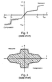
- Fig. 3 corresponds to the damper in which the damping force increases and decreases according to another function of the piston velocity, where after exceeding by the piston velocity some predefined activation threshold (V AT ), additional damping forces are generated so that the damping force progressively increases in order to slow down the accelerated masses to a greater extent.
- V AT some predefined activation threshold
- Additional damping forces may be achieved e.g. by providing the piston assembly with additional valves acting after the piston reaches the velocity activation threshold. Comparing Fig. 2 and Fig. 4 , one may easily note that application of an additional compression and rebound valve assemblies would enable to obtain the same amount of dissipated energy (area under the curve) for a shorter stroke of a car suspension. However, it is visible in Fig. 3 that the damping force changes along the same path for the piston velocity increase or decrease. In other words, in this approach, the activation threshold and deactivation threshold are the same.
- Fig. 5 schematically shows the force-velocity relation for an exemplary damper, in which the method of the present invention is implemented.
- V AT activation threshold
- V MAX maximum value
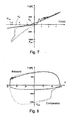
- Figs. 7 and 8 show actual characteristics obtained by the inventors during the tests of a basic damper (solid line) and the damper provided with additional passive valve assemblies on the compression side, which implements the method of the present invention (dashed line). Both dampers were tested on a rig with the same sinusoidal excitation. The valve assemblies of the second damper were adjusted so that the activation threshold (V AT ) was about 2.5 m/s, the deactivation threshold (V DT ) was about 0 m/s and the maximum force (F MAX ) of about 11 kN at V MAX .
- V AT activation threshold
- V DT deactivation threshold
- F MAX maximum force
- the thresholds V AT and V DT of the method of the present invention should be adjusted in dependence on application.
Landscapes
- Engineering & Computer Science (AREA)
- Mechanical Engineering (AREA)
- General Engineering & Computer Science (AREA)
- Physics & Mathematics (AREA)
- Fluid Mechanics (AREA)
- Fluid-Damping Devices (AREA)
- Vehicle Body Suspensions (AREA)
- Vibration Dampers (AREA)
Priority Applications (3)
| Application Number | Priority Date | Filing Date | Title |
|---|---|---|---|
| AT07003045T ATE467066T1 (de) | 2007-02-13 | 2007-02-13 | VERFAHREN ZUR VERNICHTUNG VON STOSSBELASTUNGEN HYDRAULISCHER STOßDÄMPFER |
| EP07003045A EP1959155B1 (de) | 2007-02-13 | 2007-02-13 | Verfahren zur Vernichtung von Stossbelastungen hydraulischer Stoßdämpfer |
| DE602007006275T DE602007006275D1 (de) | 2007-02-13 | 2007-02-13 | Verfahren zur Vernichtung von Stossbelastungen hydraulischer Stoßdämpfer |
Applications Claiming Priority (1)
| Application Number | Priority Date | Filing Date | Title |
|---|---|---|---|
| EP07003045A EP1959155B1 (de) | 2007-02-13 | 2007-02-13 | Verfahren zur Vernichtung von Stossbelastungen hydraulischer Stoßdämpfer |
Publications (2)
| Publication Number | Publication Date |
|---|---|
| EP1959155A1 true EP1959155A1 (de) | 2008-08-20 |
| EP1959155B1 EP1959155B1 (de) | 2010-05-05 |
Family
ID=38191860
Family Applications (1)
| Application Number | Title | Priority Date | Filing Date |
|---|---|---|---|
| EP07003045A Active EP1959155B1 (de) | 2007-02-13 | 2007-02-13 | Verfahren zur Vernichtung von Stossbelastungen hydraulischer Stoßdämpfer |
Country Status (3)
| Country | Link |
|---|---|
| EP (1) | EP1959155B1 (de) |
| AT (1) | ATE467066T1 (de) |
| DE (1) | DE602007006275D1 (de) |
Cited By (1)
| Publication number | Priority date | Publication date | Assignee | Title |
|---|---|---|---|---|
| EP3489049A1 (de) * | 2017-11-28 | 2019-05-29 | Volvo Car Corporation | Elektronischer dämpfer mit hoher schlagzähigkeit (ehid) |
Citations (6)
| Publication number | Priority date | Publication date | Assignee | Title |
|---|---|---|---|---|
| FR1181645A (fr) * | 1957-08-26 | 1959-06-17 | Veb | Amortisseurs pour véhicules |
| FR2041630A5 (de) * | 1969-05-08 | 1971-01-29 | Simca Automobiles Sa | |
| EP0409094A1 (de) * | 1989-07-15 | 1991-01-23 | Stabilus GmbH | Lenkungsdämpfer |
| EP1215414A1 (de) * | 2000-12-16 | 2002-06-19 | Stabilus GmbH | Kolben-Zylinderaggregat mit einer geschwindigkeitsabhängigen Dämpfkraft |
| US20030010587A1 (en) * | 2000-01-26 | 2003-01-16 | Valentin Eroshenko | Damper with high dissipating power |
| EP1538367A1 (de) * | 2003-12-01 | 2005-06-08 | ZF Friedrichshafen AG | Dämpfventileinrichtung mit progressiver Dämpfkraftkennlinie |
-
2007
- 2007-02-13 AT AT07003045T patent/ATE467066T1/de not_active IP Right Cessation
- 2007-02-13 DE DE602007006275T patent/DE602007006275D1/de active Active
- 2007-02-13 EP EP07003045A patent/EP1959155B1/de active Active
Patent Citations (6)
| Publication number | Priority date | Publication date | Assignee | Title |
|---|---|---|---|---|
| FR1181645A (fr) * | 1957-08-26 | 1959-06-17 | Veb | Amortisseurs pour véhicules |
| FR2041630A5 (de) * | 1969-05-08 | 1971-01-29 | Simca Automobiles Sa | |
| EP0409094A1 (de) * | 1989-07-15 | 1991-01-23 | Stabilus GmbH | Lenkungsdämpfer |
| US20030010587A1 (en) * | 2000-01-26 | 2003-01-16 | Valentin Eroshenko | Damper with high dissipating power |
| EP1215414A1 (de) * | 2000-12-16 | 2002-06-19 | Stabilus GmbH | Kolben-Zylinderaggregat mit einer geschwindigkeitsabhängigen Dämpfkraft |
| EP1538367A1 (de) * | 2003-12-01 | 2005-06-08 | ZF Friedrichshafen AG | Dämpfventileinrichtung mit progressiver Dämpfkraftkennlinie |
Cited By (2)
| Publication number | Priority date | Publication date | Assignee | Title |
|---|---|---|---|---|
| EP3489049A1 (de) * | 2017-11-28 | 2019-05-29 | Volvo Car Corporation | Elektronischer dämpfer mit hoher schlagzähigkeit (ehid) |
| US10792970B2 (en) | 2017-11-28 | 2020-10-06 | Volvo Car Corporation | Method for a vehicle, an arrangement for a vehicle and a vehicle |
Also Published As
| Publication number | Publication date |
|---|---|
| ATE467066T1 (de) | 2010-05-15 |
| DE602007006275D1 (de) | 2010-06-17 |
| EP1959155B1 (de) | 2010-05-05 |
Similar Documents
| Publication | Publication Date | Title |
|---|---|---|
| Wu et al. | A semi-active control policy to reduce the occurrence and severity of end-stop impacts in a suspension seat with an electrorheological fluid damper | |
| JP3479647B2 (ja) | 振動ダンパー | |
| EP1664578B1 (de) | Hubabhängige umgehung | |
| EP3039312B1 (de) | Stossdämpfer mit frequenzabhängigem passivem ventil | |
| US8457841B2 (en) | Suspension system with optimized damping response | |
| US9080634B2 (en) | Shock absorber with frequency dependent passive valve | |
| KR20170012194A (ko) | 주파수 의존형 수동 밸브를 가지는 충격 흡수기 | |
| EP1548322A1 (de) | Dämpfer | |
| US8757333B2 (en) | Vibration damping method | |
| CN114810911A (zh) | 冲程依赖性阻尼器组件 | |
| CN109973584B (zh) | 一种重卡驾驶室减震器的温控设计方法 | |
| KR101008298B1 (ko) | 자기유변유체를 이용한 일체형 현가장치 | |
| EP1959155B1 (de) | Verfahren zur Vernichtung von Stossbelastungen hydraulischer Stoßdämpfer | |
| US20220412425A1 (en) | Vehicle Shock Absorber | |
| KR102152027B1 (ko) | 쇽업소버 | |
| US10047816B2 (en) | Damping strut with a hydraulic shock absorber and method for operating the damping strut | |
| GB2341909A (en) | A frequency dependent fluid damper for a vehicle suspension. | |
| CN109838495A (zh) | 汽车悬架减振器总成 | |
| KR0116172Y1 (ko) | 현가장치의 쇽 업소오버 | |
| KR102302543B1 (ko) | 유압식 댐퍼용 밸브 | |
| WO2018082958A1 (en) | Shock absorber and vehicle | |
| JP2004036871A (ja) | セミアクティブ油圧緩衝器 | |
| Senar | Double Hydraulic Stop (DHS) Suspension | |
| JPH0658360A (ja) | 車両用油圧緩衝器 | |
| CN109070677B (zh) | 车辆的液压悬架系统 |
Legal Events
| Date | Code | Title | Description |
|---|---|---|---|
| PUAI | Public reference made under article 153(3) epc to a published international application that has entered the european phase |
Free format text: ORIGINAL CODE: 0009012 |
|
| AK | Designated contracting states |
Kind code of ref document: A1 Designated state(s): AT BE BG CH CY CZ DE DK EE ES FI FR GB GR HU IE IS IT LI LT LU LV MC NL PL PT RO SE SI SK TR |
|
| AX | Request for extension of the european patent |
Extension state: AL BA HR MK RS |
|
| 17P | Request for examination filed |
Effective date: 20090220 |
|
| AKX | Designation fees paid |
Designated state(s): AT BE BG CH CY CZ DE DK EE ES FI FR GB GR HU IE IS IT LI LT LU LV MC NL PL PT RO SE SI SK TR |
|
| GRAP | Despatch of communication of intention to grant a patent |
Free format text: ORIGINAL CODE: EPIDOSNIGR1 |
|
| GRAS | Grant fee paid |
Free format text: ORIGINAL CODE: EPIDOSNIGR3 |
|
| GRAA | (expected) grant |
Free format text: ORIGINAL CODE: 0009210 |
|
| AK | Designated contracting states |
Kind code of ref document: B1 Designated state(s): AT BE BG CH CY CZ DE DK EE ES FI FR GB GR HU IE IS IT LI LT LU LV MC NL PL PT RO SE SI SK TR |
|
| REG | Reference to a national code |
Ref country code: GB Ref legal event code: FG4D |
|
| REG | Reference to a national code |
Ref country code: CH Ref legal event code: EP |
|
| REG | Reference to a national code |
Ref country code: IE Ref legal event code: FG4D |
|
| REF | Corresponds to: |
Ref document number: 602007006275 Country of ref document: DE Date of ref document: 20100617 Kind code of ref document: P |
|
| REG | Reference to a national code |
Ref country code: NL Ref legal event code: VDEP Effective date: 20100505 |
|
| LTIE | Lt: invalidation of european patent or patent extension |
Effective date: 20100505 |
|
| PG25 | Lapsed in a contracting state [announced via postgrant information from national office to epo] |
Ref country code: ES Free format text: LAPSE BECAUSE OF FAILURE TO SUBMIT A TRANSLATION OF THE DESCRIPTION OR TO PAY THE FEE WITHIN THE PRESCRIBED TIME-LIMIT Effective date: 20100816 Ref country code: NL Free format text: LAPSE BECAUSE OF FAILURE TO SUBMIT A TRANSLATION OF THE DESCRIPTION OR TO PAY THE FEE WITHIN THE PRESCRIBED TIME-LIMIT Effective date: 20100505 Ref country code: SE Free format text: LAPSE BECAUSE OF FAILURE TO SUBMIT A TRANSLATION OF THE DESCRIPTION OR TO PAY THE FEE WITHIN THE PRESCRIBED TIME-LIMIT Effective date: 20100505 Ref country code: LT Free format text: LAPSE BECAUSE OF FAILURE TO SUBMIT A TRANSLATION OF THE DESCRIPTION OR TO PAY THE FEE WITHIN THE PRESCRIBED TIME-LIMIT Effective date: 20100505 |
|
| PG25 | Lapsed in a contracting state [announced via postgrant information from national office to epo] |
Ref country code: AT Free format text: LAPSE BECAUSE OF FAILURE TO SUBMIT A TRANSLATION OF THE DESCRIPTION OR TO PAY THE FEE WITHIN THE PRESCRIBED TIME-LIMIT Effective date: 20100505 Ref country code: SI Free format text: LAPSE BECAUSE OF FAILURE TO SUBMIT A TRANSLATION OF THE DESCRIPTION OR TO PAY THE FEE WITHIN THE PRESCRIBED TIME-LIMIT Effective date: 20100505 Ref country code: FI Free format text: LAPSE BECAUSE OF FAILURE TO SUBMIT A TRANSLATION OF THE DESCRIPTION OR TO PAY THE FEE WITHIN THE PRESCRIBED TIME-LIMIT Effective date: 20100505 Ref country code: LV Free format text: LAPSE BECAUSE OF FAILURE TO SUBMIT A TRANSLATION OF THE DESCRIPTION OR TO PAY THE FEE WITHIN THE PRESCRIBED TIME-LIMIT Effective date: 20100505 Ref country code: IS Free format text: LAPSE BECAUSE OF FAILURE TO SUBMIT A TRANSLATION OF THE DESCRIPTION OR TO PAY THE FEE WITHIN THE PRESCRIBED TIME-LIMIT Effective date: 20100905 |
|
| PG25 | Lapsed in a contracting state [announced via postgrant information from national office to epo] |
Ref country code: PL Free format text: LAPSE BECAUSE OF FAILURE TO SUBMIT A TRANSLATION OF THE DESCRIPTION OR TO PAY THE FEE WITHIN THE PRESCRIBED TIME-LIMIT Effective date: 20100505 Ref country code: CY Free format text: LAPSE BECAUSE OF FAILURE TO SUBMIT A TRANSLATION OF THE DESCRIPTION OR TO PAY THE FEE WITHIN THE PRESCRIBED TIME-LIMIT Effective date: 20100602 |
|
| PG25 | Lapsed in a contracting state [announced via postgrant information from national office to epo] |
Ref country code: EE Free format text: LAPSE BECAUSE OF FAILURE TO SUBMIT A TRANSLATION OF THE DESCRIPTION OR TO PAY THE FEE WITHIN THE PRESCRIBED TIME-LIMIT Effective date: 20100505 Ref country code: DK Free format text: LAPSE BECAUSE OF FAILURE TO SUBMIT A TRANSLATION OF THE DESCRIPTION OR TO PAY THE FEE WITHIN THE PRESCRIBED TIME-LIMIT Effective date: 20100505 Ref country code: GR Free format text: LAPSE BECAUSE OF FAILURE TO SUBMIT A TRANSLATION OF THE DESCRIPTION OR TO PAY THE FEE WITHIN THE PRESCRIBED TIME-LIMIT Effective date: 20100806 Ref country code: PT Free format text: LAPSE BECAUSE OF FAILURE TO SUBMIT A TRANSLATION OF THE DESCRIPTION OR TO PAY THE FEE WITHIN THE PRESCRIBED TIME-LIMIT Effective date: 20100906 |
|
| PG25 | Lapsed in a contracting state [announced via postgrant information from national office to epo] |
Ref country code: SK Free format text: LAPSE BECAUSE OF FAILURE TO SUBMIT A TRANSLATION OF THE DESCRIPTION OR TO PAY THE FEE WITHIN THE PRESCRIBED TIME-LIMIT Effective date: 20100505 Ref country code: BE Free format text: LAPSE BECAUSE OF FAILURE TO SUBMIT A TRANSLATION OF THE DESCRIPTION OR TO PAY THE FEE WITHIN THE PRESCRIBED TIME-LIMIT Effective date: 20100505 Ref country code: CZ Free format text: LAPSE BECAUSE OF FAILURE TO SUBMIT A TRANSLATION OF THE DESCRIPTION OR TO PAY THE FEE WITHIN THE PRESCRIBED TIME-LIMIT Effective date: 20100505 Ref country code: RO Free format text: LAPSE BECAUSE OF FAILURE TO SUBMIT A TRANSLATION OF THE DESCRIPTION OR TO PAY THE FEE WITHIN THE PRESCRIBED TIME-LIMIT Effective date: 20100505 |
|
| PLBE | No opposition filed within time limit |
Free format text: ORIGINAL CODE: 0009261 |
|
| STAA | Information on the status of an ep patent application or granted ep patent |
Free format text: STATUS: NO OPPOSITION FILED WITHIN TIME LIMIT |
|
| 26N | No opposition filed |
Effective date: 20110208 |
|
| REG | Reference to a national code |
Ref country code: DE Ref legal event code: R097 Ref document number: 602007006275 Country of ref document: DE Effective date: 20110207 |
|
| PG25 | Lapsed in a contracting state [announced via postgrant information from national office to epo] |
Ref country code: MC Free format text: LAPSE BECAUSE OF NON-PAYMENT OF DUE FEES Effective date: 20110228 |
|
| REG | Reference to a national code |
Ref country code: CH Ref legal event code: PL |
|
| GBPC | Gb: european patent ceased through non-payment of renewal fee |
Effective date: 20110213 |
|
| PG25 | Lapsed in a contracting state [announced via postgrant information from national office to epo] |
Ref country code: LI Free format text: LAPSE BECAUSE OF NON-PAYMENT OF DUE FEES Effective date: 20110228 Ref country code: CH Free format text: LAPSE BECAUSE OF NON-PAYMENT OF DUE FEES Effective date: 20110228 |
|
| REG | Reference to a national code |
Ref country code: IE Ref legal event code: MM4A |
|
| PG25 | Lapsed in a contracting state [announced via postgrant information from national office to epo] |
Ref country code: IT Free format text: LAPSE BECAUSE OF NON-PAYMENT OF DUE FEES Effective date: 20110213 |
|
| PG25 | Lapsed in a contracting state [announced via postgrant information from national office to epo] |
Ref country code: IE Free format text: LAPSE BECAUSE OF NON-PAYMENT OF DUE FEES Effective date: 20110213 |
|
| PG25 | Lapsed in a contracting state [announced via postgrant information from national office to epo] |
Ref country code: GB Free format text: LAPSE BECAUSE OF NON-PAYMENT OF DUE FEES Effective date: 20110213 |
|
| PG25 | Lapsed in a contracting state [announced via postgrant information from national office to epo] |
Ref country code: LU Free format text: LAPSE BECAUSE OF NON-PAYMENT OF DUE FEES Effective date: 20110213 |
|
| PG25 | Lapsed in a contracting state [announced via postgrant information from national office to epo] |
Ref country code: BG Free format text: LAPSE BECAUSE OF FAILURE TO SUBMIT A TRANSLATION OF THE DESCRIPTION OR TO PAY THE FEE WITHIN THE PRESCRIBED TIME-LIMIT Effective date: 20100805 Ref country code: TR Free format text: LAPSE BECAUSE OF FAILURE TO SUBMIT A TRANSLATION OF THE DESCRIPTION OR TO PAY THE FEE WITHIN THE PRESCRIBED TIME-LIMIT Effective date: 20100505 |
|
| PG25 | Lapsed in a contracting state [announced via postgrant information from national office to epo] |
Ref country code: HU Free format text: LAPSE BECAUSE OF FAILURE TO SUBMIT A TRANSLATION OF THE DESCRIPTION OR TO PAY THE FEE WITHIN THE PRESCRIBED TIME-LIMIT Effective date: 20100505 |
|
| REG | Reference to a national code |
Ref country code: FR Ref legal event code: PLFP Year of fee payment: 10 |
|
| REG | Reference to a national code |
Ref country code: FR Ref legal event code: PLFP Year of fee payment: 11 |
|
| REG | Reference to a national code |
Ref country code: FR Ref legal event code: CA Effective date: 20171124 Ref country code: FR Ref legal event code: TP Owner name: BWI COMPANY LIMITED S.A., LU Effective date: 20171124 |
|
| REG | Reference to a national code |
Ref country code: FR Ref legal event code: PLFP Year of fee payment: 12 |
|
| REG | Reference to a national code |
Ref country code: DE Ref legal event code: R081 Ref document number: 602007006275 Country of ref document: DE Owner name: BWI COMPANY LIMITED S.A., LU Free format text: FORMER OWNER: DELPHI TECHNOLOGIES, INC., TROY, MICH., US Ref country code: DE Ref legal event code: R082 Ref document number: 602007006275 Country of ref document: DE |
|
| PGFP | Annual fee paid to national office [announced via postgrant information from national office to epo] |
Ref country code: DE Payment date: 20241231 Year of fee payment: 19 |
|
| PGFP | Annual fee paid to national office [announced via postgrant information from national office to epo] |
Ref country code: FR Payment date: 20260218 Year of fee payment: 20 |