EP1959164A2 - Différentiel de véhicule - Google Patents
Différentiel de véhicule Download PDFInfo
- Publication number
- EP1959164A2 EP1959164A2 EP08151453A EP08151453A EP1959164A2 EP 1959164 A2 EP1959164 A2 EP 1959164A2 EP 08151453 A EP08151453 A EP 08151453A EP 08151453 A EP08151453 A EP 08151453A EP 1959164 A2 EP1959164 A2 EP 1959164A2
- Authority
- EP
- European Patent Office
- Prior art keywords
- pinion gear
- pinion
- gears
- pair
- differential
- Prior art date
- Legal status (The legal status is an assumption and is not a legal conclusion. Google has not performed a legal analysis and makes no representation as to the accuracy of the status listed.)
- Withdrawn
Links
- 230000002093 peripheral effect Effects 0.000 claims description 43
- 238000003780 insertion Methods 0.000 claims description 42
- 230000037431 insertion Effects 0.000 claims description 42
- 238000010276 construction Methods 0.000 description 13
- 125000006850 spacer group Chemical group 0.000 description 12
- 230000000694 effects Effects 0.000 description 9
- 230000033001 locomotion Effects 0.000 description 5
- 230000001105 regulatory effect Effects 0.000 description 5
- 238000005299 abrasion Methods 0.000 description 2
- 230000005540 biological transmission Effects 0.000 description 2
- 230000000717 retained effect Effects 0.000 description 2
- 230000000881 depressing effect Effects 0.000 description 1
- 230000007774 longterm Effects 0.000 description 1
- 238000000034 method Methods 0.000 description 1
- 238000003825 pressing Methods 0.000 description 1
- 238000013341 scale-up Methods 0.000 description 1
Images




Classifications
-
- F—MECHANICAL ENGINEERING; LIGHTING; HEATING; WEAPONS; BLASTING
- F16—ENGINEERING ELEMENTS AND UNITS; GENERAL MEASURES FOR PRODUCING AND MAINTAINING EFFECTIVE FUNCTIONING OF MACHINES OR INSTALLATIONS; THERMAL INSULATION IN GENERAL
- F16H—GEARING
- F16H48/00—Differential gearings
- F16H48/06—Differential gearings with gears having orbital motion
- F16H48/08—Differential gearings with gears having orbital motion comprising bevel gears
-
- F—MECHANICAL ENGINEERING; LIGHTING; HEATING; WEAPONS; BLASTING
- F16—ENGINEERING ELEMENTS AND UNITS; GENERAL MEASURES FOR PRODUCING AND MAINTAINING EFFECTIVE FUNCTIONING OF MACHINES OR INSTALLATIONS; THERMAL INSULATION IN GENERAL
- F16H—GEARING
- F16H48/00—Differential gearings
- F16H48/06—Differential gearings with gears having orbital motion
- F16H48/08—Differential gearings with gears having orbital motion comprising bevel gears
- F16H2048/087—Differential gearings with gears having orbital motion comprising bevel gears characterised by the pinion gears, e.g. their type or arrangement
-
- F—MECHANICAL ENGINEERING; LIGHTING; HEATING; WEAPONS; BLASTING
- F16—ENGINEERING ELEMENTS AND UNITS; GENERAL MEASURES FOR PRODUCING AND MAINTAINING EFFECTIVE FUNCTIONING OF MACHINES OR INSTALLATIONS; THERMAL INSULATION IN GENERAL
- F16H—GEARING
- F16H48/00—Differential gearings
- F16H48/38—Constructional details
- F16H2048/387—Shields or washers
-
- F—MECHANICAL ENGINEERING; LIGHTING; HEATING; WEAPONS; BLASTING
- F16—ENGINEERING ELEMENTS AND UNITS; GENERAL MEASURES FOR PRODUCING AND MAINTAINING EFFECTIVE FUNCTIONING OF MACHINES OR INSTALLATIONS; THERMAL INSULATION IN GENERAL
- F16H—GEARING
- F16H48/00—Differential gearings
- F16H48/38—Constructional details
- F16H48/40—Constructional details characterised by features of the rotating cases
Definitions
- the invention relates to a differential for a vehicle, and more particularly to a differential for a vehicle including a pinion gear shaft for preventing falling of a pinion gear which receives a rotation driving force from a drive side.
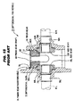
- the differential 71 for a vehicle includes a differential case 72 which rotates by receiving an engine torque, side gears 73 L and 73 R which are provided in parallel with each other along an axis line of rotation of the differential case 72 , and a pinion gear 74 which is engaged with each of the side gears 73 L and 73 R.
- the differential case 72 is provided with a pinion gear insertion hole 75 , and axle insertion holes 76 L and 76 R.
- an axis line of the pinion gear insertion hole 75 , and each of axis lines of the axle insertion holes 76 L and 76 R are at right angles to each other.
- the differential case 72 is provided with a recess groove 78 which is formed in an inner surface of the pinion gear insertion hole 75 and to which a snap ring 77 is fitted.
- the side gears 73 L and 73 R are constituted by unbottomed cylindrical bevel gears which have a boss portion 79L and a gear portion 80 L, and a boss portion 79 R and a gear portion 80 R, respectively. Also, the side gears 73 L and 73 R are disposed so as to be movable in the axis line of rotation of the differential case 72 , and are supported rotatably within the differential case 72 so that the boss portions 79 L and 79 R face the axle insertion holes 76 L and 76 R, respectively.
- Axles 81 L and 81 R are spline-fitted into the side gears 73 L and 73 R, respectively, with parts of the axles 81 L and 81 R positioned within the axle insertion holes 76 L and 76 R, respectively.
- Annular sliding members 82 L and 82 R which are located in the circumstances of the boss portions 79 L and 79 R, respectively, are interposed between the gear portion 80 L (back surface) of the side gear 73 L, and an inner opening periphery of the axle insertion hole 76 L, and between the gear portion 80 R (back surface) of the side gear 73 R, and an inner opening periphery of the axle insertion hole 76 R, respectively.
- the pinion gear 74 is constituted by an unbottomed cylindrical bevel gear. Also, the pinion gear 74 is retained by a pinion gear holding plate 83 interposed between the snap ring 77 and the pinion gear 74 , and is rotatably supported within the pinion insertion hole 75 . A pinion gear shaft 84 for preventing gear falling is inserted through a center of an axle of the pinion gear 74 .
- the left-hand and right-hand axles are connected to the side gears 73 L and 73 R, respectively, through the spline fitting, the torque from the engine side is distributed depending on the driving situation of the vehicle to be transmitted to the left-hand and right-hand axles through the drive pinion, the ring gear, the differential case 72 , the pinion gear 74 , and the side gears 73 L and 73 R.
- the seizure or the partial abrasion is generated either in the pinion gear 74 or in the pinion gear hole 75 . It is thought that in the differential for a vehicle described in Utility Model Registration No. 2,520,728 , the pinion gear 74 is formed to have a larger diameter than that of each of the side gears 73 L and 73 R, and the pinion gear shaft 84 is inserted through the central portion of an axle of the pinion gear 74 , thereby avoiding that problem.
- the pinion gear 74 must not be rotatably supported by a pinion gear shaft 84 , but an outer peripheral surface of the pinion gear 74 must frictionally slide on an inner peripheral surface of the pinion gear insertion hole 75 in a state of being parallel therewith.
- a gap defined between the inner peripheral surface of the pinion gear 74 and the outer peripheral surface of the pinion gear shaft 84 can not be made smaller than that defined between the outer peripheral surface of the pinion gear 74 and the inner peripheral surface of the pinion gear insertion hole 75 .
- the pinion gear 74 is not rotatably supported in a normal state by the pinion shaft 84, If the pinion gear 74 is rotatably supported in the normal state by the pinion shaft 84 , this is made when the pinion gear 74 is inclined. Therefore, it is thought that even with the construction as described above, the inclination of the pinion gear 74 can not be yet reliably removed, especially, the seizure or the partial abrasion can not be prevented from being generated in an edge portion in a direction of the center of an axle of the pinion gear shaft 84 in the sliding portion between the pinion gear 74 and the pinion gear insertion hole 75 .
- a differential for a vehicle including: a differential case; one pair of side gears rotatably accommodated in the differential case; at least one pair of pinion gears engaged at right angles with the one pair of side gears, shaft insertion holes being provided in central portions of axles of the at least one pair of pinion gears, respectively ; and a pinion gear shaft inserted through the shaft insertion holes and supported by the differential case; in which the differential case has a first pinion gear supporting portion for rotatably supporting outer peripheral surfaces of the at least one pair of pinion gears, the pinion gear shaft has a second pinion gear supporting portion for rotatably supporting the at least one pair of pinion gears by sliding on inner surfaces of the shaft insertion holes, and the second pinion gear supporting portion is disposed on a side of an axis line of rotation of the differential case with respect to the first pinion gear supporting portion.
- a differential for a vehicle including: a differential case; one pair of side gears rotatably accommodated in the differential case; at least one pair of pinion gears engaged at right angles with the one pair of side gears, each of the at least one pair of pinion gears having hole portions each opening on a side of an axis line of rotation of the differential case; and a supporting member interposed between the at least one pair of pinion gears, and between the one pair of side gears; in which the differential case has a first pinion gear supporting portion for rotatably supporting outer peripheral surfaces of the at least one pair of pinion gears, and the supporting member has a second pinion gear supporting portion for being brought into contact with opening inner surfaces of the hole portions to rotatably support the at least one pair of pinion gears.
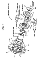
- FIG. 1 is an exploded perspective view explaining a differential for a vehicle according to a first embodiment of the invention
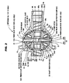
- FIG. 2 is a cross sectional view explaining the differential for a vehicle according to the first embodiment of the invention
- FIG. 3 is a perspective view explaining a differential case of the differential for a vehicle according to the first embodiment of the invention.
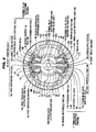
- FIG. 4 is a cross sectional view showing an assembled pinion gear of the differential for a vehicle according to the first embodiment of the invention in a state of being cut at right angles to an axis line of rotation of the differential case shown in FIG. 3 .
- FIG. 5 is a cross sectional view explaining a stable operation of the pinion gear in the differential for a vehicle according to the first embodiment of the invention.
- FIG. 6 is a cross sectional view explaining the differential case in the differential for a vehicle according to the first embodiment of the invention.
- FIG. 7 is a perspective view explaining the pinion gear of the differential for a vehicle according to the first embodiment of the invention.
- a differential 1 for a vehicle is roughly composed of a differential case 2 which rotates by receiving an engine torque, a pinion gear shaft 50 which is located on an axis line at right angles to an axis line, O, of rotation of the differential case 2 , one pair of (upper and lower two) pinion gears 3 and 4 which are disposed in parallel with each other on the pinion gear shaft 50 , one pair of (left-hand and right-hand two) side gears 5 L and 5 R which are engaged at right angles with the upper and lower two pinion gears 3 and 4 , and thrust washers 6 L and 6 R which are located on back surface sides of the left-hand and right-hand two side gears 5 L and 5 R, respectively.
- the differential case 2 has in its inside a space portion 2 A for accommodating therein the pinion gears 3 and 4 , the side gears 5 L and 5 R, and the thrust washers 6 L and 6 R, and differential oil introducing portions 7 and 8 for introducing a differential oil into a space defined between sliding surfaces (first supported portions 3 a and 4 a of base portions 3 M and 4 M which will be described later, and second supported portions 3 b and 4 b of gear portions 3 N and 4 N which will be described later) of the pinion gears 3 and 4 , and supporting surfaces (first pinion gear supporting surfaces 10 a and 10 b of pinion gear back surface holes 10 A and 11 A which will be described later, and second pinion gear supporting surfaces 10 b and 11 b of extension portions 10 B and 11 B which will be described later) of pinion gear supporting portions 10 and 11 .
- the entire differential case 2 is formed in the form of an integral one-piece member.
- the differential oil introducing portions 7 and 8 are composed of protrusions 7 a and 8 a for paddling the differential oil by rotation of the differential case 2 , and the pinion gears 3 and 4 .
- the protrusions 7 and 8 are formed integrally with the extension portions 10 B and 11 B which will be described later so as to extend from second pinion gear supporting surfaces 10 b and 11 b to the side of the axis line of rotation of the differential case 2 , respectively, and are disposed in two positions along rotation directions of the pinion gears 3 and 4, respectively.
- the differential case 2 is provided with left-hand and right-hand two axle insertion holes 9 L and 9 R which open along an axis line, O, of rotation, and the pair of upper and lower pinion gear supporting portions 10 and 11 which have the axis lines in a direction at right angles to the axis lines of the axle insertion holes 9 L and 9 R.
- the differential case 2 is provided with side gear passing holes 12 L and 12 R which are located in respective regions symmetrical with respect to the axis line, O, of rotation, that is, portions which are circumferentially located at equal intervals away from the pinion gear supporting portions 10 and 11. As shown in FIGS.
- annular ring gear attaching flange 13 is integrally provided on the side of the left-hand axle of the differential case 2 so as to be parallel with the circumferential direction within a plane at right angles to the axis line, O, of rotation.
- the axle insertion holes 9 L and 9 R are formed in the form of through holes each opening in a direction along the axis line, O, of rotation.
- Left-hand and right-hand axles (not shown) are inserted through the axle insertion holes 9 L and 9 R, respectively.
- Thrust washer receiving portions 9 La and 9 Ra each having a spherical surface, which receive the thrust washers 6 L and 6 R, respectively, are provided in the inner opening peripheries of the axle insertion holes 9 L and 9 R, respectively.
- the pinion gear supporting portions 10 and 11 are composed of a pinion gear back surface hole 10 A and an extension portion 10 B, and a pinion gear back surface hole 11 A and an extension portion 11 B, respectively.
- each of the pinion gear back surface holes 10 A and 11 A is formed in the form of a stepped through hole which opens inside and outside the differential case 2 and in which the inside of the differential case 2 is enlarged in its diameter while having an axis line at right angles to the axis line, O, of rotation.
- each of the pinion gear back surface holes 10 A and 11 A functions as a processing hole as well for a pinion gear supporting hole.
- An inner opening size of each of the pinion gear back surface holes 10 A and 11 A is set as a size having a minor diameter (a minor diameter smaller than the major diameter of each of the side gears 5 L and 5 R) approximately equal to a major diameter of each of the pinion gears 3 and 4 .
- Inner surfaces of the pinion gear back surface holes 10 A and 11 A are formed in the form of first pinion gear supporting surfaces 10 a and 11 a which rotatably support first supported portions (portions other than the second supported portions 3 b and 4 b as outer peripheral surfaces of portions provided with tooth surfaces of gears) 3 a and 4 a as sliding portions of the pinion gears 3 and 4 , and first pinion gear supporting surfaces 10 a and 12 a which relatively slide on the first supported portions 3 a and 4 a, respectively.
- first stepped surfaces of the pinion gear back surface holes 10 A and 11 A are respectively provided with pinion gear receiving portions (top portions) 10 M and 11 M which are formed in the form of spherical surfaces each having a predetermined curvature, and which receive the pinion gears 3 and 4 on each of which a centrifugal force acts.
- Second stepped surfaces of the pinion gear back surface holes 10 A and 11 A are respectively provided with washer receiving portions 10 C and 11 C which receive annular washers 21 and 22 each serving as a stopper body.
- the annular washers 21 and 22 are interposed between a back surface of the pinion gear 3 (a fourth supported portion 3 B) and the washer receiving portion 10 C, and between a back surface of the pinion gear 4 (a fourth supported portion 4 B) and the washer receiving portion 11 C, respectively,
- the extension portions 10 B and 11 B which are disposed in parallel at equal intervals in the circumferential direction so as to extend to the side of the axis line of rotation of the differential case 2 (the inside of the differential case 2 ) are integrally provided in the inner opening peripheries of the pinion gear back surface holes 10 A and 11 A , respectively.
- Second pinion gear supporting surfaces 10 b and 11 b are provided in the extension portions 10 B and 11 B, respectively.
- the second pinion gear supporting surfaces 10 b and 11 b support second supported portions 3 b and 4 b corresponding to the outer peripheral surfaces of the portions having the tooth surfaces of the pinion gears 3 and 4 formed therein, respectively.
- the second pinion gear supporting surfaces 10 b and 11 b are articulated with first pinion gear supporting surfaces 10 a and 11 a , respectively.
- the second pinion gear supporting surfaces 10 b and 11 b correspond, together with the first pinion gear supporting surfaces 10 a and 11 a, to "a first pinion gear supporting portion" of the invention.
- At least parts of the second pinion gear supporting surfaces 10 b and 11 b are disposed on a side opposite to the axis line, O, of rotation of the differential case 2 with respect to the engagement portions between the pinion gears 3 and 4 , and the side gears 5 L and 5 R in an axial direction of the pinion gear shaft 50 .
- each of the side gear passing holes 12 L and 12 R is formed in the form of a through hole having an opening portion having a planar non-circular shape. Also, the opening sizes of the side gear passing holes 12 L and 12 R are set as sizes allowing the pinion gears 3 and 4 , and the side gears 5 L and 5 R to be inserted into the differential case 2 .
- the pinion gear shaft 50 has pinion gear supporting surfaces 50 A and 50 B which rotatably support the pinion gears 3 and 4 , respectively, and is inserted through the pinion gears 3 and 4 (the shaft insertion holes 3 A and 4 A), and the washers 21 and 22 to be supported by the pinion gear back surface holes 10 A and 11 A of the differential case 2 .
- the pinion gear supporting surfaces 50 A and 50 B correspond to "a second pinion gear supporting portion" of the invention.
- At least parts of the pinion gear supporting surfaces 50 A and 50 B are disposed on the side of the axis line, O, of rotation with respect to the engagement portions between the pinion gears 3 and 4 , and the side gears 5 L and 5 R in the axial direction of the pinion gear shaft 50 .
- the pinion gear supporting surfaces 50 A and 50 B are disposed on the side of the axis line, O, of rotation of the differential case 2 with respect to the pinion gear supporting portions 10 and 11 . More specifically, the pinion gear supporting surfaces 50A and 50 B are disposed at a predetermined interval on the side of the axis line, O, of rotation with respect to the second pinion gear supporting surfaces 10 b and 11 b in the axial direction of the pinion gear shaft 50 .
- a spherical bulge portion 50 C protruding in a radial direction of the pinion gear shaft 50 is integrally provided approximately at a central portion in the direction of the axis line of the pinion gear shaft 50 .
- pinion gears 3 and 4 have approximately the same construction, for example, only the pinion gear 3 will now be described. It is noted that reference symbols of the portions of the pinion gear 4 are given so as to correspond to those of the portions of the pinion gears 3 (for example, a base portion of the pinion gear 4 is designated with reference symbol 4 M so as to correspond to a base portion 3 M of the pinion gear 3 , and a gear portion of the pinion gear 4 is designated with reference symbol 4 N so as to correspond to a gear portion 3 N of the pinion gear 3 ), and thus a description thereof is omitted here for the sake of simplicity.
- the pinion gear 3 is constituted by a bevel gear in which the base portion 3 M having a peripheral surface having a predetermined major diameter, and the gear portion 3 N having concave teeth C 1 and tooth grooves C 2 alternately disposed in parallel with each other in a circumferential direction are formed in the outer peripheral portion.
- the pinion gear 3 is rotatably supported by the first pinion gear supporting surface 10 a of the pinion gear back surface hole 10 A, the second pinion gear supporting surface 10 b of the extension portion 10 B, and the pinion gear supporting surface 50 A of the pinion gear shaft 50 .
- the side of the pinion gear 3 of the both sides in the direction of the rotation axis, which is located on the side of the axis line, O, of rotation of the differential case 2 when the pinion gear 3 is assembled to the differential case 2 is defined as a gear head side, and the side of the pinion gear 3 which is located on the side opposite to that side is defined as a gear base side.
- the pinion gear 3 is provided with a plurality of recess grooves 3 C, 3 C, ... serving as a differential oil inflowing portion which open to the first supported portion 3 a as the sliding surface for the first pinion gear supporting surface 10 a of the pinion gear back surface hole 10 A.
- a shaft insertion hole 3 A through which the pinion gear shaft 50 is inserted is provided at the central portion of an axle of the pinion gear 3 .
- the shaft insertion hole 3 A is formed in the form of a stepped hole having large and small two inner surfaces which are different in minor diameter from each other.
- One, having the smaller minor diameter, of both the inner surfaces of the shaft insertion hole 3 A is formed by a third supported portion 3 m which slides on the pinion gear supporting surface 50 A of the pinion gear shaft 50 .
- the other (a portion other than the third supported portion 3 m), having the larger minor diameter, of both the inner surfaces of the shaft insertion holes 3 A and 4 A is formed by a non-sliding portion 30 m which does not slide on the outer peripheral surface of the pinion gear shaft 50 .
- the base portion 3 M is formed in an end portion on a side opposite to the side gear side end portion of the pinion gear 3 , that is, a portion except for a side gear engagement portion which is engaged with each of the side gears 5 L and 5 R.
- a first supported portion 3 a corresponding to the first pinion gear supporting surface 10 a of the pinion gear back surface hole 10 A, and a second supported portion 3 b corresponding to the second pinion gear supporting surface 10 b of the extension portion 10 B are provided in an outer peripheral surface of the base portion 3 M.
- a fourth supported portion 3 B which is formed in the form of a spherical surface adapted to the pinion gear receiving portion 10 M of the pinion gear back surface hole 10 A is provided on a back surface of the pinion gear 3.
- the gear portion 3 N is composed of a straight portion Cs including the second supported portion 3 b of the pinion gear 3 , and a tapered portion Ct articulated with the straight portion Cs. Also, the gear portion 3 N is engaged with each of the side gears 5 L and 5 R on the side of the axis line, O, of rotation of the differential case 2 . The gear portion 3 N, as shown in FIG. 2 , is engaged with each of the gear portions of the side gears 5 L and 5 R.
- a portion (a central point in engagement) in which a surface pressure becomes highest at the time of transmission of the torque from the pinion gear 3 to each of the side gears 5 L and 5 R is located in the vicinity of a central point of a tooth surface of the gear portion 3 N.
- a tooth top surface c (a part of a tooth top surface of the gear engagement portion continuous to the outer peripheral surface of the base portion 3 M) of the concave tooth C 1 in the straight portion Cs is formed by a peripheral surface having a predetermined major diameter.
- the tooth top surface c of the convex tooth C 1 in the tapered portion Ct is formed by a peripheral surface which becomes smaller toward the gear head portion from the gear base portion.
- the side gears 5 L and 5 R are constructed by approximately annular gears (the bevel gears each having a larger major diameter than that of each of the pinion gears 3 and 4 , and each having a single tooth top conical angle) which have the boss portions 5 La and 5 Lb different in major diameter from each other, and the gear portions 5 Lb and 5 Rb.
- the side gears 5 L and 5 R are rotatably supported within the differential case 2 , and are engaged with the pinion gears 3 and 4 .
- the number of teeth of each of the side gears 5 L and 5 R is set as being 2.1 times or more as large as that of each of the pinion gears 3 and 4 (for example, the number of teeth of each of the pinion gears 3 and 4 is set to 7 , while the number of teeth of each of the pinion gears 5 L and 5 R is set to 15 ).
- the major diameter of each of the side gears 5 L and 5 R is set as a size which is larger than each of the major diameter of each of the pinion gears 3 and 4 , and the size of each of the extension portions 10 B and 11 B.
- Sliding portions 5 Lc and 5 Rc which are constituted by spherical surfaces adapted to the thrust washer receiving portions 9 Lc and 9 Rc through the thrust washers 6 L and 6 R are provided on the back surfaces of the side gears 5 L and 5 R, respectively.
- Left-hand and right-hand axles (not shown) are inserted through the axle insertion holes 9 L and 9 R to be spline-fitted into the side gears 5 L and 5 R, respectively.
- An axle spacer 23 as an axle movement regulating member, as shown in FIG. 2 is interposed between the side gears 5 L and 5 R.
- the axle spacer 23 has recess portions 24 and 25 having both end portions into which the head portions of the left-hand and right-hand axles are fitted, respectively, and is disposed on the axis line, O, of rotation of the differential case 2 .
- the entire axle spacer 23 is formed in the form of an approximately columnar body obtained by combining a pair of spacer elements 23 A and 23 B. As a result, the connection (spline-fitting) between the side gears 5 L and 5 R, and the left-hand and right-hand axles is smoothly and reliably carried out. Bottom surfaces of the recess portions 24 and 25 are formed by engagement surfaces 26 and 27 with which the head portions of the axles are engaged, respectively.
- the axle spacer 23 is provided with a columnar shaft insertion hole 28 through which the pinion gear shaft 50 is inserted, and a spherical inner space 29 to which the bulge portion 50 C of the pinion gear shaft 50 is fitted,to be fixed.
- the shaft insertion hole 28 is formed by providing approximately semi-columnar space portions 28 A and 28 B in the spacer elements 23 A and 23 B, respectively.
- the inner space 29 is formed by providing approximately semispherical spaces 29 A and 29 B in the spacer elements 23 A and 23 B, respectively. Also, the shaft insertion hole 28 and the inner space 29 prevent the pinion gear shaft 50 from being displaced.
- the thrust washers 6 L and 6 R are constituted by annular washers having washer main bodies 6 La and 6 Ra which receive thrust forces from the side gears 5 L and 5 R, respectively.
- the thrust washers 6 L and 6 R are interposed between the back surface of the side gear 5 L and the thrust washer receiving portion 9 Lc, and between the back surface,of the side gear 5 R and the thrust washer receiving portion and 9 Rc, respectively.
- the thrust washers 6 L and 6 R adjust the engagement between the side gears 5 L and 5 R, and the pinion gears 3 and 4 .
- Planar approximately T-like engagement pieces 30 and 31 which can be plastic-deformed are integrally on the outer peripheries of the thrust washers 6 L and 6 R, respectively.
- the engagement pieces 30 and 31 are plastic-deformed to be engaged with the outer peripheral surfaces of the side gears 5 L and 5 R, respectively, and also are disposed in the respective positions allowing the rotation of the side gears 5 L and 5 R. In addition, the engagement pieces 30 and 31 prevent the thrust washers 6 L and 6 R from being deformed radsially with respect to the side gears 5 L and 5 R, respectively.
- the thrust washers 6 L and 6 R are provided with differential oil introducing paths 32 (only one of them is illustrated in FIG. 1 ) for introducing the differential oil from the washer inner peripheral portions into the washer outer peripheral portions.
- the differential case 2 When the torque from the engine side of the vehicle is inputted to the differential case 2 through the drive pinion and the ring gear, the differential case 2 rotates around the axis line, O, of rotation. When the differential case 2 rotates, the rotating force is transmitted to the pinion gears 3 and 4 through the pinion gear shaft 50 , and is then transmitted from the pinion gears 3 and 4 to the side gears 5 L and 5 R, respectively.
- the axles (not shown) are spline-fitted into the left-hand and right-hand side gears 5 L and 5 R, respectively, the torque from the engine side is transmitted to the left-hand and right-hand axles through the drive pinion, the ring gear, the differential case 2 , the pinion gear shaft 50 , the pinion gears 3 and 4 , and the side gears 5 L and 5 R.
- the first supported portions 3 a and 4 a, and the second supported portions 3 b and 4 b slide on the first pinion gear supporting surfaces 10 a and 11 a, and the second pinion gear supporting surfaces 10 b and 11 b, respectively.
- the third supported portions 3 m and 4m slide on the pinion gear supporting surfaces 50 A and 50 B of the pinion gear shaft 50 , respectively.
- Thrust force in the direction of the rotation axis of the pinion gears 3 and 4 is generated on each of the engagement surfaces with the side gears 5 L and 5 R by the rotations of the pinion gears 3 and 4 , respectively.
- the side gears 5 L and 5 R are moved in a direction of getting away from each other by the thrust force, thereby pressing the thrust washers 6 L and 6 R against the thrust washer receiving portions 9 Lc and 9 Rc, respectively.
- the frictional resistances are generated between the thrust washers 6 L and 6 R, and the thrust washer receiving portions 9 Lc and 9 Rc, respectively.
- the differential rotations of the side gears 5 L and 5 R are limited by those frictional resistances as well.
- the pinion gear shaft 50 is inserted through the pinion gears 3 and 4 , and the washers 21 and 22 to be supported by the pinion gear back surface holes 10 A and 11 A of the differential case 2 .
- the pinion gear supporting surfaces 50 A and 50B are disposed on the side of the axis line, O, of rotation of the differential case 2 with respect to the pinion gear supporting portions 10 and 11 .
- the pinion gears 3 and 4 stably slide on the pinion gear shaft 50 . Consequently, it is possible to sufficiently exercise the effect of preventing the inclination of the pinion gears 3 and 4 by the pinion gear shaft 50 .
- a notch axially extending may be provided in the pinion gear shaft 50, and an engagement portion which is engaged with the notch to regulate the axial movement of the pinion gear shaft 50 may be formed in the axle spacer 23.
- the pinion gear shaft 50 may not be fixed to the axle spacer 23, but parts of the pinion gear back surface holes 10 A and 11 A either may be made small in their diameters or may be closed, and the pinion gear shaft 50 may be fixed to the differential case 2.
- three or four pinion gear shafts are supported by the differential case 2, and end portions of these pinion gear shafts on the side opposite to the support side end portions thereof are fixed to the axle space 23 to be integrated therewith.
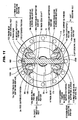
- FIG. 9 is a cross sectional view showing an assembled pinion gear of a differential for a vehicle according to a second embodiment of the invention in a state of being cut in parallel with an axis line of rotation of a differential case.
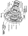
- FIG. 10 is a perspective view, parts of a differential case and the pinion gear being broken away for explanation of the differential for a vehicle according to the second embodiment of the invention.
- the same or corresponding members as those shown in FIGS. 1 to 7 are designated with the same reference numerals and reference symbols, respectively, and a detailed description thereof is omitted here for the sake of simplicity.
- the pinion gear shaft 50 has no bulge portion, and thus is formed in the form of a columnar body having a major diameter which is set as an approximately uniform size.
- the pinion gear shaft 50 is provided with a pin insertion hole 50 D which radially opens.
- a pair of notch recess portions 50 E and 50 E which open along the axis line, O, of rotation are respectively provided in portions, in the outer peripheral surface of the both end portions of the pinion gear shaft 50, which face the gear portions 5 Lb and 5 Rb of the side gears 5 L and 5 R, respectively.
- the pair of notch recess portions 50 E and 50 E in the end portions of the pinion gear shaft 50 are respectively disposed in positions which are located in parallel with each other at equal intervals (of 180 °) in the circumferential direction.
- the size, in the direction of the axis line, of each of the pair of notch recess portions 50 E and 50 E is set as being larger than that, in the direction of the axis line, of each of the shaft insertion holes 3 A and 4 A.
- an oil path is defined between the outer peripheral surface of the pinion gear shaft 50 and each of the inner peripheral surfaces of the shaft insertion holes 3 A and 4 A (between the outer peripheral surface of the pinion gear shaft 50 , and each of the third supported portions 3m and 4 m of the shaft insertion holes 3 A and 4 A, and between the outer peripheral surface of the pinion gear shaft 50 , and each of the non-sliding portions 30 m and 40 m of the shaft insertion holes 3 A and 4 A).
- the outer peripheral surface of the pinion gear shaft 50 , and the inner peripheral surfaces of the pinion gears 3 and 4 are lubricated.
- each of the pinion gear back surface holes 10 D and 11 D is set as being approximately equal to the major diameter of the pinion gear shaft 50 .
- the differential case 2 is provided with pin attaching holes 2 b and 2 b which open along the axis line, O, of rotation in the inner peripheral surface of the pinion gear back surface hole 10 D and which is disposed in parallel with each other at equal intervals (of 180 °) in the circumferential direction.
- Both end portions of a pin 52 which is inserted through the pinion insertion hole 50 D of the pinion gear shaft 50 are fixed to the pin attaching holes 2 b and 2 b, respectively.
- the pinion gear shaft 50 is supported by the differential case 2 through the pin 52 .
- the rotation of the pinion gear shaft 50 around its axis is stopped, and the pinion gear shaft 50 is axially retained.
- annular shaft supporting portions 100 D and 110 D may be provided in which the inner surface of the differential case 2 corresponding to the back surface sides of the pinion gears 3 and 4 is formed so as to protrude inward along the pinion gear shaft 50 , and the pinion gear shaft 50 may be supported by the annular shaft supporting portions 100 D and 110 D.
- a supporting structure having high rigidity is obtained as a supporting structure for the pinion gear shaft 50 .
- the surface pressure generated between the pinion gear shaft 50 and each of the shaft supporting portions 100 D and 110 D can be reduced as compared with the case where the pinion gear shaft 50 is supported by the pinion gear back surface holes 10 D and 11 D.
- the pinion gear shaft 50 may be press-filled into or welded to the hole portion formed in the differential case 2, thereby stopping the rotation of the pinion gear shaft 50.
- a part of the pinion gear shaft 50 may be cut out, and a part of the differential case 2 may be engaged with the resulting notch, thereby stopping the rotation of the pinion gear shaft 50.
- FIG. 12 is a cross sectional view showing an assembled pinion gear of a differential for a vehicle according to a third embodiment of the invention in a state of being cut in parallel with an axis line of rotation of a differential case,
- the same or corresponding members as those shown in FIGS. 1 to 7 are designated with the same reference numerals and reference symbols, respectively, and a detailed description thereof is omitted here for the sake of simplicity.
- a differential for a vehicle of this embodiment includes a supporting member 90 having pinion gear supporting portions 90 A and 90 B, as a second pinion gear supporting member, which are brought into contact with gear head side opening inner surfaces of the through holes (hole portions) 3 A and 4 A of the pinion gears 3 and 4 to rotatably support the pinion gears 3 and 4, respectively, instead of including the axle spacer 23 and the pinion gear shaft 50 in the first embodiment.
- the supporting member 90 is interposed between the side gears 5 L and 5 R, and between the pinion gears 3 and 4.
- the supporting member 90 is disposed in a position where at least parts of the pinion gear supporting portions 90 A and 90B are inserted into the through holes 3 A and 4 A, respectively, to regulate the movements of the pinion gears 3 and 4 to the side of the axis line, O, of rotation.
- the motions of the pinion gears 3 and 4 to the side of approaching the axis line, O, of rotation is regulated, and the inclination of the central axis lines of the pinion gears 3 and 4 with respect to the central axis lines of the inner peripheral surfaces of the pinion gear supporting portions 10 and 11 is regulated.
- the assembly of the differential for a vehicle can be carried out as follows. Firstly, the pinion gears 3 and 4 are fitted into the pinion gear supporting portions 10 and 11, respectively. Next, the supporting member 90 is disposed between both the pinion gears 3 and 4. After that, the side gears 5 L and 5 R are built thereinto, and the thrust washers 6 L and 6 R are interposed between the side gears 5 L and 5 R, and the differential case 2.
- the effect that the number of parts and the number of assembly processes can be reduced is obtained in addition to the effects of the first embodiment.
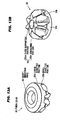
- FIGS. 13A and 13B are respectively perspective views showing a pinion gear of a differential for a vehicle according to a fourth embodiment of the invention.
- FIG. 13A shows a state in which the pinion gear is viewed from the upside
- FIG. 13B shows a state in which the pinion gear is viewed from the downside
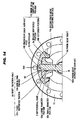
- FIG. 14 is a cross sectional view showing a state in which the pinion gear of the differential for a vehicle according to the fourth embodiment of the invention is suppressed by a pinion gear supporting portion.
- the same or corresponding members as those shown in FIGS. 1 to 7 are designated with the same reference numerals and reference symbols, respectively, and a detailed description thereof is omitted here for the sake of simplicity.
- the differential for a vehicle of this embodiment is different from that of the first embodiment in that an upper outer peripheral surface of a pinion gear 33 is composed of a large diameter portion 33 a which frictionally slides on the second pinion gear supporting surface 10 b to be located on the gear base side, and a small diameter portion 33 b which is formed to have a diameter smaller than that of the large diameter portion 33 a, and is located on the gear head side.
- an upper outer peripheral surface of a pinion gear 33 is composed of a large diameter portion 33 a which frictionally slides on the second pinion gear supporting surface 10 b to be located on the gear base side, and a small diameter portion 33 b which is formed to have a diameter smaller than that of the large diameter portion 33 a, and is located on the gear head side.
- the large diameter portion 33 a of the outer peripheral portion of the pinion gear 33 is disposed on the side of the gear base portion with respect to the central point in engagement between the pinion gear 33 , and each of the side gears 5 L and 5 R.
- a third supported portion 33 m of the shaft insertion hole 3 A of the pinion gear 33 is disposed on the side of the gear head portion with respect to the central point of the engagement between the pinion gear 33 , and each of the side gears 5 L and 5 R, That is to say, the large diameter portion 33a and the third supported portion 33 m are disposed so as to hold the above central point in engagement between the pinion gear 33 , and each of the side gears 5 L and 5 R in the axial direction of the pinion gear 33 . It is noted that since the other pinion gear paired with the pinion gear 33 is constructed approximately and identically to the pinion gear 33 , a description thereof is omitted here for the sake of simplicity.
- the large diameter portion 33 a and the third supported portion 33 m are respectively disposed on the both sides of the central point in engagement between the pinion gear 33 , and each of the side gears 5 L and 5 R so as to be located across that central point in engagement from each other.
- a depressing force due to the engagement between the pinion gear 33 , and each of the side gears 5 L and 5 R is distributed between the large diameter portion 33 a and the third supported portion 33 m in a balanced manner.
- the distribution ratio hardly changes due to the frictional wear caused by the traveling state of the vehicle, and the long-term use. Consequently, the differential limit force can be obtained in the more stable state.
- a construction may also be adopted such that the pinion gear 33 is formed in the form of a columnar body having an outer peripheral surface having a uniform major diameter, and an amount of protrusion of the second pinion gear supporting surface 10b to the axis line, O, of rotation of the differential case 2 is shortened, thereby rotatably supporting the pinion gear 33 only on the side of the gear base portion with respect to the central point in engagement by the second pinion gear supporting surface 10 b .
- a construction may also be adopted such that a first portion of the second pinion gear supporting surface on the side of the gear base portion with respect to the central point in engagement of the pinion gear 33 is made a small diameter portion having a minor diameter of a, a second portion of the second pinion gear supporting surface located on the side of the gear head portion is made a large diameter portion having a minor diameter of b (b > a), and the large diameter portion is inhibited from being brought into contact with the outer peripheral surface of the pinion gear 33 .
- differential case 2 is formed in the form of one-piece member, the invention is not limited thereto.
- the differential case 2 may also be composed of a plurality of case elements.
- a differential ( 1 ) for a vehicle includes a differential case ( 2 ), side gears ( 5 L, 5 R) rotatably accommodated in the differential case ( 2 ), pinion gears ( 3 , 4 ) engaged with the side gears ( 5 L, 5 R), and pinion gear shaft ( 50 ) inserted through the pinion gears ( 3 , 4 ) to be supported by the differential case ( 2 ), in which the differential case ( 2 ) has pinion gear supporting portions ( 10 , 11 ) for rotatably supporting the pinion gears ( 3 , 4 ), respectively, the pinion gear shaft ( 50 ) has pinion gear supporting surfaces ( 50 A, 50 B) for rotatably supporting the pinion gears ( 3 , 4 ), respectively, and the pinion gear supporting surfaces ( 50 A, 50 B) are disposed on a side of an axis line of rotation of the differential case ( 2 ) with respect to the pinion gear supporting portions ( 10, 11 ).
Landscapes
- Engineering & Computer Science (AREA)
- General Engineering & Computer Science (AREA)
- Mechanical Engineering (AREA)
- Retarders (AREA)
- Motor Power Transmission Devices (AREA)
Applications Claiming Priority (2)
| Application Number | Priority Date | Filing Date | Title |
|---|---|---|---|
| JP2007033697 | 2007-02-14 | ||
| JP2007106358A JP5109453B2 (ja) | 2007-02-14 | 2007-04-13 | 車両用差動装置 |
Publications (2)
| Publication Number | Publication Date |
|---|---|
| EP1959164A2 true EP1959164A2 (fr) | 2008-08-20 |
| EP1959164A3 EP1959164A3 (fr) | 2010-10-06 |
Family
ID=39323062
Family Applications (1)
| Application Number | Title | Priority Date | Filing Date |
|---|---|---|---|
| EP08151453A Withdrawn EP1959164A3 (fr) | 2007-02-14 | 2008-02-14 | Différentiel de véhicule |
Country Status (2)
| Country | Link |
|---|---|
| US (1) | US8092335B2 (fr) |
| EP (1) | EP1959164A3 (fr) |
Families Citing this family (6)
| Publication number | Priority date | Publication date | Assignee | Title |
|---|---|---|---|---|
| US8216105B2 (en) * | 2007-11-02 | 2012-07-10 | Jtekt Corporation | Differential apparatus for vehicle and assembling method thereof |
| JP5391605B2 (ja) * | 2008-08-04 | 2014-01-15 | 株式会社ジェイテクト | 車両用差動装置 |
| KR101025183B1 (ko) * | 2010-09-27 | 2011-04-07 | (주) 선원 밸브 | 어구용 스냅링 |
| JP6264021B2 (ja) * | 2013-12-19 | 2018-01-24 | 株式会社ジェイテクト | 車両用差動装置 |
| JP6711093B2 (ja) * | 2016-04-07 | 2020-06-17 | 株式会社ジェイテクト | 差動装置 |
| US10352425B2 (en) * | 2017-02-14 | 2019-07-16 | American Axle & Manufacturing, Inc. | Driveline component having differential assembly with retaining member welded to differential case to retain cross-pin |
Citations (3)
| Publication number | Priority date | Publication date | Assignee | Title |
|---|---|---|---|---|
| US1446545A (en) | 1919-03-08 | 1923-02-27 | Alanson P Brush | Differential gearing |
| US4305313A (en) | 1979-12-06 | 1981-12-15 | Eaton Corporation | Differential case fastener |
| JPS5790948U (fr) | 1980-11-24 | 1982-06-04 |
Family Cites Families (2)
| Publication number | Priority date | Publication date | Assignee | Title |
|---|---|---|---|---|
| JPS5790948A (en) | 1980-11-27 | 1982-06-05 | Nippon Mining Co Ltd | Bonding wire for semiconductor element |
| JP2520728B2 (ja) | 1989-03-30 | 1996-07-31 | 株式会社ダイフク | 棚へのネット取付け構造 |
-
2008
- 2008-02-14 US US12/031,370 patent/US8092335B2/en not_active Expired - Fee Related
- 2008-02-14 EP EP08151453A patent/EP1959164A3/fr not_active Withdrawn
Patent Citations (3)
| Publication number | Priority date | Publication date | Assignee | Title |
|---|---|---|---|---|
| US1446545A (en) | 1919-03-08 | 1923-02-27 | Alanson P Brush | Differential gearing |
| US4305313A (en) | 1979-12-06 | 1981-12-15 | Eaton Corporation | Differential case fastener |
| JPS5790948U (fr) | 1980-11-24 | 1982-06-04 |
Also Published As
| Publication number | Publication date |
|---|---|
| EP1959164A3 (fr) | 2010-10-06 |
| US20080194373A1 (en) | 2008-08-14 |
| US8092335B2 (en) | 2012-01-10 |
Similar Documents
| Publication | Publication Date | Title |
|---|---|---|
| US8292775B2 (en) | Vehicle differential apparatus | |
| US8092335B2 (en) | Differential for vehicle | |
| US8216105B2 (en) | Differential apparatus for vehicle and assembling method thereof | |
| JP2008082533A (ja) | 車両用差動装置及びその組立方法 | |
| US9188213B2 (en) | Differential apparatus | |
| US20080227583A1 (en) | Differential case for vehicle and differential device for vehicle including differential case | |
| JP5817199B2 (ja) | トロイダル型無段変速機 | |
| EP4524417A1 (fr) | Joint homocinétique du type coulissant | |
| JP7398310B2 (ja) | 等速ジョイント | |
| JP5767273B2 (ja) | トリポート型等速ジョイント | |
| JP2014092263A (ja) | スラスト玉軸受及びトロイダル型無段変速機 | |
| JP5109453B2 (ja) | 車両用差動装置 | |
| JP2021173299A (ja) | 歯車装置 | |
| JP2000038003A (ja) | 車輪用転がり軸受ユニット | |
| JP5240507B2 (ja) | 摺動式トリポード型等速ジョイント | |
| JP5817282B2 (ja) | トロイダル型無段変速機 | |
| JP5747486B2 (ja) | トロイダル型無段変速機 | |
| JP2009085292A (ja) | 車両用差動装置及びその組立方法 | |
| JP6787026B2 (ja) | トロイダル型無段変速機 | |
| JP4604782B2 (ja) | 摩擦式無段変速機 | |
| JP2007292145A (ja) | トロイダル型無段変速機 | |
| JP2006275185A (ja) | トロイダル型無段変速機 | |
| JP2008208938A (ja) | トロイダル型無段変速機 | |
| JP2007040419A (ja) | トリポート型等速ジョイント | |
| JP2008202768A (ja) | 等速ジョイント |
Legal Events
| Date | Code | Title | Description |
|---|---|---|---|
| PUAI | Public reference made under article 153(3) epc to a published international application that has entered the european phase |
Free format text: ORIGINAL CODE: 0009012 |
|
| AK | Designated contracting states |
Kind code of ref document: A2 Designated state(s): AT BE BG CH CY CZ DE DK EE ES FI FR GB GR HR HU IE IS IT LI LT LU LV MC MT NL NO PL PT RO SE SI SK TR |
|
| AX | Request for extension of the european patent |
Extension state: AL BA MK RS |
|
| PUAL | Search report despatched |
Free format text: ORIGINAL CODE: 0009013 |
|
| AK | Designated contracting states |
Kind code of ref document: A3 Designated state(s): AT BE BG CH CY CZ DE DK EE ES FI FR GB GR HR HU IE IS IT LI LT LU LV MC MT NL NO PL PT RO SE SI SK TR |
|
| AX | Request for extension of the european patent |
Extension state: AL BA MK RS |
|
| 17P | Request for examination filed |
Effective date: 20110314 |
|
| AKX | Designation fees paid |
Designated state(s): DE |
|
| 17Q | First examination report despatched |
Effective date: 20120417 |
|
| STAA | Information on the status of an ep patent application or granted ep patent |
Free format text: STATUS: THE APPLICATION IS DEEMED TO BE WITHDRAWN |
|
| 18D | Application deemed to be withdrawn |
Effective date: 20180901 |