EP1959308A2 - Bilderzeugungsvorrichtung - Google Patents
Bilderzeugungsvorrichtung Download PDFInfo
- Publication number
- EP1959308A2 EP1959308A2 EP08101588A EP08101588A EP1959308A2 EP 1959308 A2 EP1959308 A2 EP 1959308A2 EP 08101588 A EP08101588 A EP 08101588A EP 08101588 A EP08101588 A EP 08101588A EP 1959308 A2 EP1959308 A2 EP 1959308A2
- Authority
- EP
- European Patent Office
- Prior art keywords
- fixing unit
- image forming
- unit
- temperature
- power
- Prior art date
- Legal status (The legal status is an assumption and is not a legal conclusion. Google has not performed a legal analysis and makes no representation as to the accuracy of the status listed.)
- Withdrawn
Links
Images


Classifications
-
- G—PHYSICS
- G03—PHOTOGRAPHY; CINEMATOGRAPHY; ANALOGOUS TECHNIQUES USING WAVES OTHER THAN OPTICAL WAVES; ELECTROGRAPHY; HOLOGRAPHY
- G03G—ELECTROGRAPHY; ELECTROPHOTOGRAPHY; MAGNETOGRAPHY
- G03G15/00—Apparatus for electrographic processes using a charge pattern
- G03G15/20—Apparatus for electrographic processes using a charge pattern for fixing, e.g. by using heat
- G03G15/2003—Apparatus for electrographic processes using a charge pattern for fixing, e.g. by using heat using heat
- G03G15/2014—Apparatus for electrographic processes using a charge pattern for fixing, e.g. by using heat using heat using contact heat
- G03G15/2039—Apparatus for electrographic processes using a charge pattern for fixing, e.g. by using heat using heat using contact heat with means for controlling the fixing temperature
-
- G—PHYSICS
- G03—PHOTOGRAPHY; CINEMATOGRAPHY; ANALOGOUS TECHNIQUES USING WAVES OTHER THAN OPTICAL WAVES; ELECTROGRAPHY; HOLOGRAPHY
- G03G—ELECTROGRAPHY; ELECTROPHOTOGRAPHY; MAGNETOGRAPHY
- G03G15/00—Apparatus for electrographic processes using a charge pattern
- G03G15/20—Apparatus for electrographic processes using a charge pattern for fixing, e.g. by using heat
- G03G15/2003—Apparatus for electrographic processes using a charge pattern for fixing, e.g. by using heat using heat
- G03G15/2014—Apparatus for electrographic processes using a charge pattern for fixing, e.g. by using heat using heat using contact heat
- G03G15/2053—Structural details of heat elements, e.g. structure of roller or belt, eddy current, induction heating
-
- G—PHYSICS
- G03—PHOTOGRAPHY; CINEMATOGRAPHY; ANALOGOUS TECHNIQUES USING WAVES OTHER THAN OPTICAL WAVES; ELECTROGRAPHY; HOLOGRAPHY
- G03G—ELECTROGRAPHY; ELECTROPHOTOGRAPHY; MAGNETOGRAPHY
- G03G15/00—Apparatus for electrographic processes using a charge pattern
- G03G15/50—Machine control of apparatus for electrographic processes using a charge pattern, e.g. regulating differents parts of the machine, multimode copiers, microprocessor control
- G03G15/5004—Power supply control, e.g. power-saving mode, automatic power turn-off
Definitions
- the present invention relates to an image forming apparatus and more particularly, to an image forming apparatus which supplies electric power to a fixing unit and a method of controlling a temperature of the fixing unit thereof
- a conventional image forming apparatus forms a predetermined image based on printing data.
- a conventional image forming apparatus achieves image formation, which includes a photosensitive medium 11, an electrifier 12 which electrifies the photosensitive medium 11 in uniform electric potential, an exposure unit 13 which scans light corresponding to printing data to the photosensitive medium 11 and forms an electrostatic latent image, a developing unit 14 which includes a developer and deposits the developer on the electrostatic latent image formed to the electrified photosensitive medium 11, and a transfer unit 15 which transfers a toner developed on the electrified photosensitive medium 11 to a printing medium using a transfer belt 16.
- the fixing unit 20 includes a heat roller 22 which is heated up to the temperature of about 200°, and also includes a pressing roller 24 to press an image onto a printing medium.
- a fixing unit temperature control circuit first confirms whether an image forming unit 10 has been initialized. Electric power is supplied to the fixing unit 20 after initialization has been completed. Accordingly, since an image can only be printed on a printing medium after both of the initialization of the image forming unit 10 and warming-up of the fixing unit 20 are completed, a user's standby time is undesirably prolonged.
- the present invention provides an image forming apparatus and controlling a temperature of a fixing unit thereof, which supplies electric power to the fixing unit together with initialization of an image forming unit, to thereby minimize a standby time of printing on a printing medium.
- an image forming apparatus including an image forming unit to form an image, a fixing unit to fix the image which is formed by the image forming unit and transferred on a printing medium, a power supply unit to supply electric power to the fixing unit, a first fixing unit control part to control the power supply unit to supply electric power to the fixing unit if initialization of the image forming unit is ended, and a second fixing unit control part to control the power supply unit to supply electric power to the fixing unit while the initialization is performed by the first fixing unit control part.
- the second fixing unit control part may control the power supply unit to supply electric power to the fixing unit if an external electric power is applied.
- the second fixing unit control part may discontinue control of the power supply unit if the initialization of the image forming unit is ended.
- the second fixing unit control part may further include a comparator to compare a highest electric power level which is permitted to the fixing unit with an electric power level which is supplied to the fixing unit, to thus control the power supply unit to cut off the electric power supplied to the fixing unit if the supplied electric power level is higher than the highest electric power level according to the comparison result.
- the fixing unit may fix the transferred image on the printing medium by radiant heat generated from a halogen lamp.
- a temperature control method of a fixing unit in an image forming apparatus including an image forming unit which forms an image and the fixing unit which fixes the image which is formed by the image forming unit and transferred on a printing medium, the temperature control method including performing an initializing operation corresponding to the image forming unit, and supplying electric power to the fixing unit while the initialization is performed.
- the supplying of electric power to the fixing unit may include supplying electric power to the fixing unit if an external electric power is applied.
- the supplying of the electric power to the fixing unit may further include discontinuing control of the electric power to be supplied to the fixing unit in the case that initialization of the image forming unit is ended.
- the supplying of the electric power to the fixing unit further includes comparing a highest electric power level which is permitted to the fixing unit with an electric power level which is supplied to the fixing unit, and cutting off the electric power supplied to the fixing unit if the supplied electric power level is higher than the highest electric power level.
- the fixing unit may perform the fixing by radiant heat generated from a halogen lamp.
- a fixing unit control part to control temperature of a fixing unit of an image forming apparatus
- the fixing unit control part comprising a temperature sensor to sense the temperature of the fixing unit, a first control circuit to control the fixing unit to generate heat during an initialization of the image forming apparatus, and a second control circuit to control the fixing unit to generate heat during the initialization of the image forming apparatus, wherein the first control circuit controls the second control circuit to cut off power supplied to the fixing unit based on a comparison between the temperature sensed by the temperature sensor and a predetermined reference temperature.
- the initialization may start upon receipt of an external power or a command to perform printing in the image forming apparatus.
- the first control part may comprise a controller to control the fixing unit to emit heat based on the comparison between the temperature of the fixing unit and the predetermined reference temperature.
- the controller may cut off power supplied to the fixing unit when the temperature sensed by the temperature sensor is greater than the predetermined reference temperature.
- the controller may cut off power supplied to the second control unit when the temperature sensed by the temperature sensor is greater than the predetermined reference temperature.
- an image forming apparatus comprising an image forming unit to form an image to be transferred onto a printing medium, a fixing unit to fix the image onto the printing medium, a temperature sensor to sense a temperature of the fixing unit, and a plurality of fixing unit control parts to selectively supply power to the fixing unit based on a comparison between the temperature of the fixing unit and a predetermined reference temperature and one of initialization and printing of the image forming unit.
- the at least two of the plurality of fixing unit control parts may supply power to the fixing unit during the initialization of the image forming apparatus.
- the at least one of the plurality of fixing unit control parts may control at least another one of the plurality of fixing unit control parts to stop supplying power to the fixing unit based on the comparison between the temperature of the fixing unit and the predetermined reference temperature.
- the supply of power may be stopped when the temperature of the fixing unit exceeds the predetermined reference temperature.
- the plurality of fixing unit control parts may selectively supply power to the fixing unit if a temperature of the fixing unit is below the predetermined reference temperature.
- Each of the plurality of fixing unit control parts may comprise a comparator to compare the temperature of the fixing unit to the predetermined reference temperature.
- At least one of the plurality of fixing unit control parts may comprise a comparator to compare the temperature of the fixing unit to the reference temperature, and a circuit to determine whether the power is supplied to the fixing unit.
- a method of controlling temperature of a fixing unit of an image forming apparatus comprising sensing the temperature of the fixing unit, controlling the fixing unit to generate heat during an initialization of the image forming apparatus with a first control circuit, controlling the fixing unit to generate heat during the initialization of the image forming apparatus with a second control circuit, wherein the first control circuit controls the second control circuit to cut off power supplied to the fixing unit based on a comparison between the sensed temperature sensed and a predetermined reference temperature.
- the initialization may start upon receipt of an external power or a command to perform printing in the image forming apparatus.
- the method may further comprise cutting off power supplied to the fixing unit when the sensed temperature is greater than the predetermined reference temperature.
- the method may further comprise cutting off power supplied to the second control unit when the sensed temperature is greater than the predetermined reference temperature.
- an image forming apparatus comprising forming an electrostatic latent image on a printing medium, sensing a temperature of a fixing unit, selectively supplying power to the fixing unit based on a comparison between the temperature of the fixing unit and a predetermined reference temperature and one of initialization and printing of the image forming apparatus, and fixing the electrostatic latent image onto the printing medium.
- the method may further comprise selectively supplying power to the fixing unit if a temperature of the fixing unit is below the predetermined reference temperature.
- the selectively supplying power to the fixing unit may be performed by a plurality of fixing unit control parts.
- the method may further comprise supplying power to the fixing unit during the initialization of the image forming apparatus using at least two of the plurality of fixing unit control parts.
- the method may further comprise selectively controlling at least one of the plurality of fixing unit control parts to stop supplying power to the fixing unit based on the comparison between the temperature of the fixing unit and the predetermined reference temperature.
- the supply of power may be stopped when the temperature of the fixing unit exceeds the predetermined reference temperature.
- FIG. 2 is a block diagram illustrating a configuration of an image forming apparatus 100 according to an embodiment of the present invention.
- the image forming apparatus 100 includes an image forming unit 10, a fixing unit 20, a power supply unit 30, a first fixing unit control part 40 and a second fixing unit control part 50, and is implemented in an electrophotographic printing device.
- the image forming apparatus 100 of Figure 2 may have a similar structure to the conventional image forming apparatus of Figure 1 .
- the image forming unit 10 forms an image based on printing data.
- the image forming unit 10 according to an embodiment of the present invention includes a photosensitive medium 11, an electrifying unit 12, an exposure unit 13, a developing unit 14 and a transfer unit 15.
- the photosensitive medium 11 forms an electrostatic latent image based on printing data.
- the electrifying unit 12 electrifies the photosensitive medium 11 in a predetermined electric potential.
- the exposure unit 13 scans light on photosensitive medium 11, to form the electrostatic latent image.
- the developing unit 14 supplies toner to the photosensitive medium 11, on which the electrostatic latent image has been formed, to form a visible image.
- the printing medium passes between the photosensitive medium 11 and the transfer unit 15 by a conveying (or transfer) belt 16. Accordingly, the visible image which has been developed on the photosensitive medium 11 is transferred to the printing medium surface facing the photosensitive medium 11.
- the image which has been formed by the image forming unit 10 and transferred on the printing medium is fixed on the printing medium by the fixing unit 20 through thermal pressing.
- the fixing unit 20 includes a heat roller 22 including a heater (not illustrated) therein to emit heat, and a pressing roller 24 which contacts the heat roller 22 to form a fixing nip.
- the heat roller 22 and the pressing roller 24 rotate in engagement with each other at a predetermined pressure, to apply heat and pressure to the image formed by the image forming unit 10 to thereby fix the image on the printing medium.
- a heating unit which generates heat may be provided in at least one of the heat roller 22 and the pressing roller 24.
- the fixing unit 20 includes a temperature sensor 26 which measures temperature on one or more outer circumferential surfaces of the heat roller 22 and/or the pressing roller 24, and a fixing unit controller 28 which controls temperature or an amount of heat radiation of the heat roller 22 according to the temperature measured by the temperature sensor 26.
- the heater included in the heat roller 22 may be implemented as one of a halogen lamp, a heat wire and an induction heater, and the temperature sensor 26 may be embodied as a thermistor having a feature of a relatively large resistance change even with a small temperature change.
- the fixing unit controller 28 includes a photocoupler 28a which transfers an output signal output from the first fixing control part 40 and/or the second fixing control part 50, a Triac 28b, which is turned on when an output signal corresponding to the turn-on signal is transmitted from the photocoupler 28a, and transmits an alternating-current (AC) power to the heat roller 22 of the fixing unit 20, and a relay 28c which controls power supplied to the heat roller 22.
- a photocoupler 28a which transfers an output signal output from the first fixing control part 40 and/or the second fixing control part 50
- a Triac 28b which is turned on when an output signal corresponding to the turn-on signal is transmitted from the photocoupler 28a, and transmits an alternating-current (AC) power to the heat roller 22 of the fixing unit 20, and a relay 28c which controls power supplied to the heat roller 22.
- AC alternating-current
- the power supply unit 30 supplies electric power to the image forming unit 10 and the fixing unit 20.
- the power supply unit 30 according to an embodiment of the present invention supplies electric power to the heat roller 22 of the fixing unit 20, by a Pulse Width Modulation (PWM) method.
- the power supply unit 30 may also include a High Voltage Power Supply (HVPS) which applies high tension electric power to the image forming unit 10.
- HVPS High Voltage Power Supply
- the first fixing unit control part 40 controls the power supply unit 30 to supply electric power to the image forming unit 10 during initialization of the image forming unit 10 and controls the power supply unit 30 to supply electric power to the fixing unit 20 after initialization of the image forming unit 10 is completed.
- the initialization of the image forming apparatus 100 may include initialization of an HDD (not illustrated) that stores, for example, image data to correspond to the electrostatic latent image as well as to the heating of the fixing unit 20. It is not possible for the first fixing unit control part 40 to control the supply of electric power to the fixing unit 20 during initialization of the image forming unit 10.
- the first fixing unit control part 40 includes a comparator 42 which compares the temperature of the fixing unit 20, which is sensed by the temperature sensor 26, with a predetermined highest temperature according to heat radiation of the fixing unit 20, and a transistor block 44 including transistors Q1, Q2, and Q3.
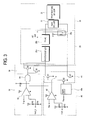
- Figure 3 is a circuit diagram illustrating a fixing unit control part of the image forming apparatus 100 according to an embodiment of the present invention.
- the first fixing unit control part 40 includes a controller 40a which reads the temperature sensed by the temperature sensor 26 and outputs a signal to turn on either the transistor Q2 or the transistor Q3 according to the temperature sensed. If the temperature sensed by the temperature sensor 26 is higher than the predetermined highest temperature according to the heat radiation of the fixing unit 20, then the transistor Q2 is turned on. In contrast, if the temperature sensed by the temperature sensor 26 is lower than the predetermined highest temperature according to the heat radiation of the fixing unit 20, then the transistor Q3 is turned on. When the transistor Q3 is turned on, a relay 28c of the fixing unit controller 28 is also turned on, and thus an alternating current (AC) power is applied to the fixing unit 20. The transistor Q2 and the transistor Q3 are never on simultaneously.
- AC alternating current
- the comparator 42 included in the first fixing unit control part 40 compares the temperature of the fixing unit 20 that is sensed by the temperature sensor 26 with the predetermined highest temperature according to the heat radiation of the fixing unit 20, and outputs a high-level signal when the sensed temperature of the fixing unit 20 is lower than the predetermined highest temperature according to the heat radiation of the fixing unit 20, that is, when an electric potential corresponding to the highest temperature is lower than the electric potential of the temperature sensor 26. Accordingly, an electric potential level of a point "A" becomes high and the transistor Q1 is turned on. As a result, the photocoupler 28a of the fixing unit controller 28 is turned on and the Triac is turned on so that the alternating current (AC) power is applied to the heat roller 22 of the fixing unit 20, to thus emit heat.
- AC alternating current
- the comparator 42 outputs a low-level signal when the sensed temperature of the fixing unit 20 is higher than the predetermined highest temperature according to the heat radiation of the fixing unit 20, that is, when an electric potential corresponding to the highest temperature is higher than the electric potential of the temperature sensor 26.
- the photocoupler 28a of the fixing unit controller 28 opens, and the Triac 28b is turned off. As a result, power supply to the heat roller 22 of the fixing unit 20 is cut off.
- the controller 40a senses that the temperature of the fixing unit 20 is continuously ascending according to an electric potential level of the temperature sensor 26 included in the fixing unit 20, the first fixing unit control part 40 opens the transistor Q3, to thereby turn off the relay 28c included in the fixing unit controller 28 to abruptly interrupt electric power being supplied to the fixing unit 20.
- the second fixing unit control part 50 controls the power supply unit 30 to supply electric power to the fixing unit 20 while the first fixing unit control part 40 performs initialization of the image forming unit 10.
- the second fixing unit control part 50 includes a comparator 52 which compares the temperature of the fixing unit 20 that is sensed by the temperature sensor 26 with a reference temperature, an AND circuit 54 which determines whether electric power is supplied to the fixing unit 20 according to whether electric power is being supplied to the image forming unit 10, and a transistor block 56 including transistors Q4 and Q5, whose powered states are determined according to an output of the AND circuit 54.
- the second fixing unit control part 50 will be described in detail with reference to Figure 3 . If an external power is applied to the image forming apparatus 100, an output signal becomes a high level through a resistor R5, and thus a level of an output signal of the AND circuit 54, which is dependent upon a level of an output signal from the comparator 52, is determined.
- the electric potential of the temperature sensor 26 included in the fixing unit 20 in the present embodiment is higher than that corresponding to the predetermined highest temperature according to the heat radiation of the fixing unit 20. Therefore, the level of the output signal from the comparator 52 becomes high, and the level of the output signal of the AND circuit 54 becomes also high.
- the level of the output signal from the comparator 52 included in the second fixing unit control part 50 becomes low, and thus the level of the output signal from the AND circuit 54 also becomes low.
- the transistors Q4 and Q5 open, and the photocoupler 28a included in the fixing unit controller 28 is turned off to thereby open the Triac 28b and the relay 28c to cut off heat radiation of the heat roller 22.
- the first fixing unit control part 40 applies a low-level signal to the second fixing unit control part 50. If the AND circuit 54 of the second fixing unit control part 50 receives the low-level signal from the controller 40a of the first fixing unit control part 40, even when the level of the output signal from the comparator 52 is high, the transistors Q4 and Q5 open to interrupt heat radiation of the heat roller 22.
- the first and second fixing unit control parts 40, 50 therefore operate mutually exclusively with respect to the control of the supply of power to the fixing unit 20. Accordingly, an overlapping supply of power to the fixing unit 20, via both the first and second fixing unit control parts 40, 50, can be prevented.
- the second fixing unit control part 50 supplies electric power to the fixing unit 20 during initialization of the image forming unit 10, and only when the temperature of the fixing unit 20 that is sensed by the temperature sensor 26 is not higher than a predetermined value (i.e., the predetermined highest temperature according to the heat radiation of the fixing unit 20).
- the temperature of the fixing unit 20 is lower in comparison to when the electric power is supplied to the fixing unit 20 to perform a fixing operation. Further, it takes a lot of time to reach temperature necessary to fix an image on a printing medium. In particular, it takes a lot of time to emit heat at a certain temperature when a heater equipped in the heat roller 22 of the fixing unit 20 is implemented by a halogen lamp.
- the second fixing unit control part 50 supplies electric power to the fixing unit 20 while the initialization of the image forming unit 10 is executed, to thereby reduce a user's standby time.
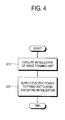
- the first fixing unit control part 40 performs an initialization operation of the image forming unit 10.
- the second fixing unit control part 50 supplies electric power to the fixing unit 20 while the first fixing unit control part 40 executes the initialization of the image forming unit 10 in operation S10. Accordingly, in operation S20, electric power can be supplied to the fixing unit 20 when an external power is applied to the image forming apparatus 100. Further, in operation S20, the electric power may be supplied to the fixing unit 20 if the temperature of the fixing unit 20 is not higher than a predetermined value (i.e., the predetermined highest temperature according to the heat radiation of the fixing unit 20), such as when an external power is initially applied to the image forming apparatus 100.
- a predetermined value i.e., the predetermined highest temperature according to the heat radiation of the fixing unit 20
- operation S20 may further include an operation of cutting off supplying of electric power to the fixing unit 20 when the initialization of the image forming unit 10 ends. Accordingly, the overlapping supply of electric power to the fixing unit 20 can be prevented.
- operation S20 may further include the operations of comparing the highest electric power level which is permitted to the fixing unit 20 with the electric power level which is supplied to the fixing unit 20 according to the temperature that is sensed by the temperature sensor 26, and blocking electric power supply to the fixing unit 20 when the electric power level that is supplied to the fixing unit 20 is larger than the highest electric power level in the fixing unit 20, according to the comparison result. Accordingly, this can also prevent the overlapping supply of power to the fixing unit 20.
- the present invention provides an image forming apparatus and a method of controlling a temperature of a fixing unit thereof, in which electric power is supplied to a fixing unit while an image forming unit is initialized, to thereby minimize a user's standby time of printing on a printing medium.
Landscapes
- Physics & Mathematics (AREA)
- General Physics & Mathematics (AREA)
- Engineering & Computer Science (AREA)
- Microelectronics & Electronic Packaging (AREA)
- Fixing For Electrophotography (AREA)
- Control Or Security For Electrophotography (AREA)
- Accessory Devices And Overall Control Thereof (AREA)
Applications Claiming Priority (1)
| Application Number | Priority Date | Filing Date | Title |
|---|---|---|---|
| KR1020070015065A KR20080075742A (ko) | 2007-02-13 | 2007-02-13 | 화상형성장치 및 그 정착기 온도제어방법 |
Publications (2)
| Publication Number | Publication Date |
|---|---|
| EP1959308A2 true EP1959308A2 (de) | 2008-08-20 |
| EP1959308A3 EP1959308A3 (de) | 2014-05-28 |
Family
ID=39430994
Family Applications (1)
| Application Number | Title | Priority Date | Filing Date |
|---|---|---|---|
| EP08101588.5A Withdrawn EP1959308A3 (de) | 2007-02-13 | 2008-02-13 | Bilderzeugungsvorrichtung |
Country Status (4)
| Country | Link |
|---|---|
| US (1) | US20080193155A1 (de) |
| EP (1) | EP1959308A3 (de) |
| KR (1) | KR20080075742A (de) |
| CN (1) | CN101246330A (de) |
Families Citing this family (4)
| Publication number | Priority date | Publication date | Assignee | Title |
|---|---|---|---|---|
| US8639145B2 (en) * | 2010-11-03 | 2014-01-28 | Kabushiki Kaisha Toshiba | Image forming apparatus and method |
| JP6140639B2 (ja) * | 2014-04-17 | 2017-05-31 | 京セラドキュメントソリューションズ株式会社 | 定着装置及びそれを備えた画像形成装置 |
| JP6594047B2 (ja) * | 2015-05-29 | 2019-10-23 | キヤノン株式会社 | 定着装置 |
| KR20170084817A (ko) * | 2016-01-13 | 2017-07-21 | 에스프린팅솔루션 주식회사 | 정착기를 컨트롤하는 방법 및 화상형성장치 |
Family Cites Families (8)
| Publication number | Priority date | Publication date | Assignee | Title |
|---|---|---|---|---|
| JPS58105180A (ja) * | 1981-12-17 | 1983-06-22 | Fuji Xerox Co Ltd | 複写機の電力制御装置 |
| WO2001048560A1 (en) * | 1999-12-28 | 2001-07-05 | Toshiba Tec Kabushiki Kaisha | Image forming device and fixing device |
| WO2001048557A1 (fr) * | 1999-12-28 | 2001-07-05 | Toshiba Tec Kabushiki Kaisha | Dispositif de formation d'image dote d'un dispositif fixateur pour fixer l'image formee par le revelateur sur un support d'enregistrement, par chauffage par induction de rouleau chauffant |
| JP2002304088A (ja) * | 2001-04-09 | 2002-10-18 | Ricoh Co Ltd | 画像形成装置 |
| JP3664136B2 (ja) * | 2002-01-22 | 2005-06-22 | 村田機械株式会社 | ヒータ通電制御回路 |
| US20030235422A1 (en) * | 2002-06-24 | 2003-12-25 | Toshiba Tec Kabushiki Kaisha | Image forming apparatus |
| JP2004061559A (ja) * | 2002-07-24 | 2004-02-26 | Toshiba Tec Corp | 定着装置 |
| KR100608017B1 (ko) * | 2004-12-14 | 2006-08-02 | 삼성전자주식회사 | 순시적으로 전력을 제어하는 정착장치 |
-
2007
- 2007-02-13 KR KR1020070015065A patent/KR20080075742A/ko not_active Withdrawn
-
2008
- 2008-01-15 US US12/014,247 patent/US20080193155A1/en not_active Abandoned
- 2008-02-03 CN CNA2008100057127A patent/CN101246330A/zh active Pending
- 2008-02-13 EP EP08101588.5A patent/EP1959308A3/de not_active Withdrawn
Also Published As
| Publication number | Publication date |
|---|---|
| KR20080075742A (ko) | 2008-08-19 |
| CN101246330A (zh) | 2008-08-20 |
| US20080193155A1 (en) | 2008-08-14 |
| EP1959308A3 (de) | 2014-05-28 |
Similar Documents
| Publication | Publication Date | Title |
|---|---|---|
| KR101273509B1 (ko) | 화상형성장치 및 상기 화상형성장치의 정착유닛 제어방법 | |
| US6959158B2 (en) | Fixing device and image forming apparatus | |
| US7228084B2 (en) | Image forming apparatus and fixing device | |
| EP2498137B1 (de) | Heizvorrichtung und damit ausgerüstete Bilderzeugungsvorrichtung | |
| US8311424B2 (en) | Fixing device usable with an image forming apparatus | |
| KR100491577B1 (ko) | 화상형성 장치의 정착기의 온도제어 방법 | |
| US20030091359A1 (en) | Power control method and apparatus for fusing roller of electrophotographic image forming apparatus | |
| JP7292906B2 (ja) | 定着装置及び画像形成装置 | |
| EP1959308A2 (de) | Bilderzeugungsvorrichtung | |
| KR100552483B1 (ko) | 화상 형성 장치의 정착 시스템 및 그 온도 제어 방법 | |
| JP2004198535A (ja) | 定着装置の温度制御方法および画像形成装置 | |
| JP2011107447A (ja) | 画像形成装置 | |
| JP2004233745A (ja) | 定着ヒータ制御装置及び画像形成装置 | |
| US7965956B2 (en) | Image forming apparatus preventing power supply during initialization and control method thereof | |
| JPH11167307A (ja) | 画像形成装置 | |
| US10503106B2 (en) | Image forming apparatus and image forming method | |
| JP2023045369A (ja) | 画像形成装置およびその制御方法 | |
| JP3569408B2 (ja) | 被加熱体温度制御方法 | |
| JPH03221983A (ja) | 画像形成装置 | |
| JP4332397B2 (ja) | 定着装置 | |
| KR20040000055A (ko) | 화상 형성 장치의 정착기 온도 제어방법 | |
| JP2003151720A (ja) | 加熱装置、及びこれを備えた画像形成装置 | |
| JP4786165B2 (ja) | 画像形成装置 | |
| JP5359421B2 (ja) | 定着装置と画像形成装置とプログラム | |
| JP2023059808A (ja) | 画像形成装置およびその制御方法 |
Legal Events
| Date | Code | Title | Description |
|---|---|---|---|
| PUAI | Public reference made under article 153(3) epc to a published international application that has entered the european phase |
Free format text: ORIGINAL CODE: 0009012 |
|
| AK | Designated contracting states |
Kind code of ref document: A2 Designated state(s): AT BE BG CH CY CZ DE DK EE ES FI FR GB GR HR HU IE IS IT LI LT LU LV MC MT NL NO PL PT RO SE SI SK TR |
|
| AX | Request for extension of the european patent |
Extension state: AL BA MK RS |
|
| RAP1 | Party data changed (applicant data changed or rights of an application transferred) |
Owner name: SAMSUNG ELECTRONICS CO., LTD. |
|
| PUAL | Search report despatched |
Free format text: ORIGINAL CODE: 0009013 |
|
| AK | Designated contracting states |
Kind code of ref document: A3 Designated state(s): AT BE BG CH CY CZ DE DK EE ES FI FR GB GR HR HU IE IS IT LI LT LU LV MC MT NL NO PL PT RO SE SI SK TR |
|
| AX | Request for extension of the european patent |
Extension state: AL BA MK RS |
|
| RIC1 | Information provided on ipc code assigned before grant |
Ipc: G03G 15/20 20060101ALI20140424BHEP Ipc: G03G 15/00 20060101AFI20140424BHEP |
|
| AKY | No designation fees paid | ||
| AXX | Extension fees paid |
Extension state: BA Extension state: RS Extension state: MK Extension state: AL |
|
| REG | Reference to a national code |
Ref country code: DE Ref legal event code: R108 |
|
| REG | Reference to a national code |
Ref country code: DE Ref legal event code: R108 Effective date: 20150204 |
|
| STAA | Information on the status of an ep patent application or granted ep patent |
Free format text: STATUS: THE APPLICATION IS DEEMED TO BE WITHDRAWN |
|
| 18D | Application deemed to be withdrawn |
Effective date: 20141129 |