EP1959524A2 - Dispositif d'isolation électrique capable de limiter la saturation magnétique même à la réception d'une polarisation CC haute puissance et son procédé de fabrication - Google Patents
Dispositif d'isolation électrique capable de limiter la saturation magnétique même à la réception d'une polarisation CC haute puissance et son procédé de fabrication Download PDFInfo
- Publication number
- EP1959524A2 EP1959524A2 EP08101663A EP08101663A EP1959524A2 EP 1959524 A2 EP1959524 A2 EP 1959524A2 EP 08101663 A EP08101663 A EP 08101663A EP 08101663 A EP08101663 A EP 08101663A EP 1959524 A2 EP1959524 A2 EP 1959524A2
- Authority
- EP
- European Patent Office
- Prior art keywords
- core
- wire
- hole
- wires
- wrapping
- Prior art date
- Legal status (The legal status is an assumption and is not a legal conclusion. Google has not performed a legal analysis and makes no representation as to the accuracy of the status listed.)
- Withdrawn
Links
Images




Classifications
-
- H—ELECTRICITY
- H01—ELECTRIC ELEMENTS
- H01R—ELECTRICALLY-CONDUCTIVE CONNECTIONS; STRUCTURAL ASSOCIATIONS OF A PLURALITY OF MUTUALLY-INSULATED ELECTRICAL CONNECTING ELEMENTS; COUPLING DEVICES; CURRENT COLLECTORS
- H01R13/00—Details of coupling devices of the kinds covered by groups H01R12/70 or H01R24/00 - H01R33/00
- H01R13/66—Structural association with built-in electrical component
- H01R13/6608—Structural association with built-in electrical component with built-in single component
- H01R13/6633—Structural association with built-in electrical component with built-in single component with inductive component, e.g. transformer
-
- H—ELECTRICITY
- H01—ELECTRIC ELEMENTS
- H01R—ELECTRICALLY-CONDUCTIVE CONNECTIONS; STRUCTURAL ASSOCIATIONS OF A PLURALITY OF MUTUALLY-INSULATED ELECTRICAL CONNECTING ELEMENTS; COUPLING DEVICES; CURRENT COLLECTORS
- H01R13/00—Details of coupling devices of the kinds covered by groups H01R12/70 or H01R24/00 - H01R33/00
- H01R13/66—Structural association with built-in electrical component
- H01R13/719—Structural association with built-in electrical component specially adapted for high frequency, e.g. with filters
-
- H—ELECTRICITY
- H04—ELECTRIC COMMUNICATION TECHNIQUE
- H04L—TRANSMISSION OF DIGITAL INFORMATION, e.g. TELEGRAPHIC COMMUNICATION
- H04L25/00—Baseband systems
- H04L25/02—Details ; arrangements for supplying electrical power along data transmission lines
- H04L25/0264—Arrangements for coupling to transmission lines
- H04L25/0266—Arrangements for providing Galvanic isolation, e.g. by means of magnetic or capacitive coupling
-
- H—ELECTRICITY
- H04—ELECTRIC COMMUNICATION TECHNIQUE
- H04L—TRANSMISSION OF DIGITAL INFORMATION, e.g. TELEGRAPHIC COMMUNICATION
- H04L25/00—Baseband systems
- H04L25/02—Details ; arrangements for supplying electrical power along data transmission lines
- H04L25/0264—Arrangements for coupling to transmission lines
- H04L25/028—Arrangements specific to the transmitter end
- H04L25/0282—Provision for current-mode coupling
-
- H—ELECTRICITY
- H04—ELECTRIC COMMUNICATION TECHNIQUE
- H04L—TRANSMISSION OF DIGITAL INFORMATION, e.g. TELEGRAPHIC COMMUNICATION
- H04L25/00—Baseband systems
- H04L25/02—Details ; arrangements for supplying electrical power along data transmission lines
- H04L25/0264—Arrangements for coupling to transmission lines
- H04L25/028—Arrangements specific to the transmitter end
- H04L25/0284—Arrangements to ensure DC-balance
-
- Y—GENERAL TAGGING OF NEW TECHNOLOGICAL DEVELOPMENTS; GENERAL TAGGING OF CROSS-SECTIONAL TECHNOLOGIES SPANNING OVER SEVERAL SECTIONS OF THE IPC; TECHNICAL SUBJECTS COVERED BY FORMER USPC CROSS-REFERENCE ART COLLECTIONS [XRACs] AND DIGESTS
- Y10—TECHNICAL SUBJECTS COVERED BY FORMER USPC
- Y10T—TECHNICAL SUBJECTS COVERED BY FORMER US CLASSIFICATION
- Y10T29/00—Metal working
- Y10T29/49—Method of mechanical manufacture
- Y10T29/49002—Electrical device making
- Y10T29/4902—Electromagnet, transformer or inductor
- Y10T29/49071—Electromagnet, transformer or inductor by winding or coiling
Definitions
- the pair of wires may ideally have voltage potentials to ground such that a voltage in one wire of the pair is equal and opposite to the voltage in the other wire of the pair.
- one wire may have a potential of -2.5 volts and the other wire may have a potential of +2.5 volts.
- the two wires may not have exactly equal and opposite voltages. For example, one wire may have -2 volts and the other wire may have +3 volts.
- Transformer 40 may be used as an isolating magnetic device.
- Transformer 40 is formed by winding wires 44, 46, 48 and 50 around a toroid shaped core 42 formed of a conductive material.
- Core 42 has a substantially circular cross-section.
- Wires 44, 46, 48 and 50 are evenly wound around core 42 except in a gap area 38.
- a high power DC current bias is added onto an alternating current and applied to one side of transformer 40, the entire core of transformer 40 may become saturated from the induced magnetic flux. Such saturation inhibits transfer of data in the alternating current component.
- Some attempts to compensate for this problem in the prior art include using a larger core 42. However, use of a larger core is not practical in many applications including connector applications due to space limitations.
- One aspect of the invention is a method for producing an electric device.
- the method comprises inserting at least a first wire through a first hole in a core and wrapping the first wire around a first side of the core.
- the method further comprises inserting at least a second wire through a second hole in the core, the second hole being spaced from the first hole and having a long axis extending substantially parallel to a long axis of the first hole; and wrapping the second wire around a second side of the core, the second side being spaced from the first side.
- Another aspect of the invention is an electrical device produced by a method of inserting at least a first wire through a first hole in a core and wrapping the first wire around a first side of the core.
- the method further comprises inserting at least a second wire through a second hole in the core, the second hole being spaced from the first hole and having a long axis extending substantially parallel to a long axis of the first hole; and wrapping the second wire around a second side of the core, the second side being spaced from the first side.
- the connector for enabling electrical communication with a plug.
- the connector comprises a set of contacts and a filter circuit in communication with the set of contacts.
- the connector further comprises a set of terminals in communication with the filter circuit; wherein the filter circuit includes a transformer with a core.
- the transformer is produced by the steps of inserting at least a first wire through a first hole in the core and wrapping the first wire around a first side of the core.
- the transformer is further produced by inserting at least a second wire through a second hole in the core, the second hole being spaced from the first hole and having a long axis extending substantially parallel to a long axis of the first hole.
- the transformer is further produced by wrapping the second wire around a second side of the core, the second side being spaced from the first side.
- Another aspect of the invention is a method for producing an electrical device.
- the method comprises wrapping a first and second wire around a first core and inserting the first and second wire and a third and a fourth wire through a first hole in a second core.
- the method further comprises wrapping the first, second, third and fourth wires around a first side of the second core and inserting fifth, sixth, seventh and eighth wires through a second hole in the second core, the second hole being spaced from the first hole and having a long axis extending substantially parallel to a long axis of the first hole.
- the method further comprises wrapping the fifth, sixth, seventh and eighth wires around a second side of the second core, the second side being spaced from the first side; and wrapping the fifth and sixth wires around the first core.
- Yet another aspect of the invention is a connector for enabling electrical communication with a plug.
- the connector comprises a set of contacts and a filter circuit in communication with the set of contacts.
- the connector further comprises a set of terminals in communication with the filter circuit.
- the filter circuit is produced by the steps of wrapping a first and second wire around a first core and inserting the first and second wire and a third and a fourth wire through a first hole in a second core.
- the filter circuit is further produced by the steps of wrapping the first, second, third and fourth wires around a first side of the second core and inserting fifth, sixth, seventh and eighth wires through a second hole in the second core, the second hole being spaced from the first hole and having a long axis extending substantially parallel to a long axis of the first hole.
- the filter circuit is further produced by the steps of wrapping the fifth, sixth, seventh and eighth wires around a second side of the second core, the second side being spaced from the first side; and wrapping the fifth and sixth wires around the first core.
- Yet another aspect of the invention is an electrical device comprising a body having first and second holes extending therethough, the holes being spaced from one another and having longitudinal axes extending substantially parallel to one another.
- the electrical device further comprises at least one wire extending through the first hole, the wire wrapped around a first side of the body and at least a second wire extending through the second hole in the body and wrapped around a second side of the body, the second side being spaced from the first side.
- Fig. 1 is front view of a transformer in accordance with the prior art
- Fig. 2 is a side view of a core for use in accordance with an embodiment of the invention.
- Figs. 3A, 3B and 3C illustrate steps of winding wires around a core of the type shown in Fig. 2 in accordance with an embodiment of the invention
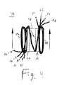
- Fig. 4 is a top view of an electric device constructed in accordance with an embodiment of the invention.
- Fig. 5 is a top view of an electric device and a common mode choke constructed in accordance with an embodiment of the invention
- Fig. 6 is a diagram of a circuit which incorporates an electric device in accordance with an embodiment of the invention.
- Fig. 7 is a diagram of a circuit and corresponding tolerances of circuit devices including an electric device in accordance with an embodiment of the invention.
- Fig. 8 is a diagram of a circuit and corresponding tolerances of circuit devices including an electric device in accordance with an embodiment of the invention.
- a core 50 resembles an ellipsoid with its ends cut off and with a substantially racetrack shaped cross-section.
- Core 50 may be made of a MgZn material with a permeability of 5000.
- core 50 includes a first hole 52 and a second hole 54 spaced from first hole 52.
- Magnetic flux lines 56 which are set up in the core during operation are also schematically shown and will become clearer upon further discussion.
- Core 50 has a first side 50a and a second side 50b. Referring to Fig.
- wires 60, 62, 64 and 66 are wrapped around core 50.
- four wires are shown simply as an example and any number of wires may be used.
- Wires 60, 62, 64 and 66 are inserted through hole 52 of core 50.
- Wires 60, 62, 64 and 66 are then wrapped around first side 50a of core 50.
- Wires 60, 62, 64 and 66 are then inserted through hole 52 again and wrapped around side 50a again for a desired number of turns. For example, X turns may be used.
- wires 60, 62, 64 and 66 have been wrapped through hole 52 and around side 50a of core 50, X number of turns, the wires are extended across either a top or bottom of core 50 for insertion into hole 54 - as shown in Fig. 3B .
- a second set of wires may be used for insertion into hole 54.
- the top and bottom of core 50 may be identical and so effectively both a top and bottom view are shown.
- wires 60, 62, 64 and 66 are then inserted through hole 54 of core 50 and then wrapped around second end 50b of core 50.
- the wires are inserted through hole 54 and wrapped around second end 50b the desired number of turns - for example, X turns. Dot notation is used to assist an assemblyman in performing the windings - where the dots indicate starting points for the wires.
- an electric device 70 in accordance with the invention is realized. Again, the extension of the wires over the top/bottom of core 50 need not be performed, if two sets of wires are used.
- device 70 may be combined with a conventional common mode choke 72 as shown in Fig. 5 .
- wires 62 and 66 are first wound around a toroid 74 having a substantially circular cross-section.
- Wires 62 and 66 (shown as being green and blue in color, respectively) are joined with wires 60 and 64 (red and natural) and wrapped through hole 52 and first side 50a.
- Wires 60, 62, 64 and 66 are then extended over a top or bottom of core 70 (except in situations where two sets of wires are used) and then wrapped through hole 54 and second side 50b.
- Wires 60, 64 remain on a left side of core 70 while wires 62 and 66 are wound again around toroid 74.
- circuit 80 which may use device 70.
- circuit 80 is a representation of the combination of device 70 and common mode choke 72 illustrated in Fig. 5 .
- magnetic flux lines occurring in a central portion of the device extend in opposing directions.
- magnetic flux lines towards distal ends of the device 70 extend in only a single direction. If such flux lines have a high enough intensity, such as may be provided by high power DC current bias, the flux may indeed saturate those portions of the device. However, as the flux lines in the central portion of the device may cancel each other out, saturation does not occur in the central portion and data transfer may still occur in that area.
- Circuit 90 may be used in a connector. As shown, contacts 92 may be used in the connector to communicate with an inserted plug (not shown). A termination circuit 94 may be used to balance a load of wires in said plug. Device 70 may be used as the load for the terminals of the plug. Choke 72 may be utilized to minimize the presence of common mode currents. As shown, optional LEDs 96 may be used. As discussed, device 70 allows data to be transmitted therethrough even in the presence of high power DC current bias and corresponding induced magnetic fields. Some tolerances which may be used for the circuit elements are shown.
- circuit 100 includes terminals 92, termination circuit 94, device 70 and choke 72. In circuit 100, four sets of devices 70 and chokes 72 are shown.
- a new electric device may be realized which can handle higher power currents and magnetizing forces which would saturate devices of the prior art.
- any number of turns may be used for each of the windings.
- the number of turns may be based on a desired return loss parameter.
- four wires are shown, clearly any number of wires may be used.
Landscapes
- Engineering & Computer Science (AREA)
- Power Engineering (AREA)
- Coils Or Transformers For Communication (AREA)
- Details Of Connecting Devices For Male And Female Coupling (AREA)
Applications Claiming Priority (1)
| Application Number | Priority Date | Filing Date | Title |
|---|---|---|---|
| US11/675,792 US20080200060A1 (en) | 2007-02-16 | 2007-02-16 | Electrical Isolation Device Capable Of Limiting Magnetic Saturation Even Upon Receipt Of High Power DC Bias And Method For Making The Same |
Publications (2)
| Publication Number | Publication Date |
|---|---|
| EP1959524A2 true EP1959524A2 (fr) | 2008-08-20 |
| EP1959524A3 EP1959524A3 (fr) | 2010-04-07 |
Family
ID=39365832
Family Applications (1)
| Application Number | Title | Priority Date | Filing Date |
|---|---|---|---|
| EP08101663A Withdrawn EP1959524A3 (fr) | 2007-02-16 | 2008-02-15 | Dispositif d'isolation électrique capable de limiter la saturation magnétique même à la réception d'une polarisation CC haute puissance et son procédé de fabrication |
Country Status (6)
| Country | Link |
|---|---|
| US (2) | US20080200060A1 (fr) |
| EP (1) | EP1959524A3 (fr) |
| CA (1) | CA2620959A1 (fr) |
| IL (1) | IL189368A0 (fr) |
| SG (1) | SG145650A1 (fr) |
| TW (1) | TW200843249A (fr) |
Families Citing this family (7)
| Publication number | Priority date | Publication date | Assignee | Title |
|---|---|---|---|---|
| CN104104350A (zh) | 2013-04-11 | 2014-10-15 | 富士康(昆山)电脑接插件有限公司 | 滤波电路及电连接器 |
| US9408335B2 (en) * | 2013-06-28 | 2016-08-02 | Cisco Technology, Inc. | ICM optimization and standardization for automation |
| EP3326246B1 (fr) | 2015-07-21 | 2022-09-21 | Bel Fuse (Macao Commercial Offshore) Limited | Fiche de connecteur modulaire pour réseaux de transmission de données à grande vitesse |
| JP6655183B2 (ja) | 2015-11-11 | 2020-02-26 | ベル フューズ (マカオ コマーシャル オフショア) リミテッド | モジュラーコネクタ |
| US10637196B2 (en) | 2015-11-11 | 2020-04-28 | Bel Fuse (Macao Commercial Offshore) Limited | Modular jack contact assembly having controlled capacitive coupling positioned within a jack housing |
| US10504647B2 (en) | 2017-04-03 | 2019-12-10 | Bel Fuse (Macao Commercial Off | Magnetic transformer having increased bandwidth for high speed data communications |
| US10530106B2 (en) | 2018-01-31 | 2020-01-07 | Bel Fuse (Macao Commercial Offshore) Limited | Modular plug connector with multilayer PCB for very high speed applications |
Family Cites Families (22)
| Publication number | Priority date | Publication date | Assignee | Title |
|---|---|---|---|---|
| BE792048A (fr) * | 1971-12-11 | 1973-03-16 | Bosch Elektronik Gmbh | Transformateur directionnel a large bande a montage en bifurcation |
| US4052785A (en) * | 1975-11-28 | 1977-10-11 | Dana Corporation | Method of making a transformer assembly |
| JP2710648B2 (ja) * | 1988-11-14 | 1998-02-10 | 日本電信電話株式会社 | 多線条平衡伝送路用コモンモードチョークコイル |
| DE69417950T2 (de) * | 1993-05-26 | 1999-09-23 | Nippon Telegraph And Telephone Corp., Tokio/Tokyo | Filter zur Erzielung der elektromagnetischen Kompatibilität für eine symmetrische mehradrige Fernmeldeleitung |
| AU3083595A (en) * | 1994-08-03 | 1996-03-04 | Madge Networks Limited | Electromagnetic interference isolator |
| US6114924A (en) * | 1997-12-11 | 2000-09-05 | Antec Corporation | Dual core RF directional coupler |
| US5956244A (en) * | 1998-03-05 | 1999-09-21 | Allen-Bradley Company Llc | Controlling currents in parallel AC/DC converters |
| US6100772A (en) * | 1998-11-16 | 2000-08-08 | Bh Electronics, Inc. | High frequency test balun with a capacitor across the output |
| US6709295B2 (en) | 2001-10-19 | 2004-03-23 | Hon Hai Precision Ind. Co., Ltd. | Connector assembly |
| US6872098B2 (en) | 2001-10-19 | 2005-03-29 | Tyco Electronics Corporation | Modular jack assembly with signal conditioning |
| US6881096B2 (en) * | 2002-04-15 | 2005-04-19 | Lantronix, Inc. | Compact serial-to-ethernet conversion port |
| TW556985U (en) | 2002-06-28 | 2003-10-01 | Hon Hai Prec Ind Co Ltd | Eclectriacl connector assembly |
| US6739915B1 (en) | 2002-11-05 | 2004-05-25 | Hon Hai Precision Ind. Co., Ltd. | Electrical connector with rear retention mechanism of outer shell |
| JP3800536B2 (ja) * | 2002-12-06 | 2006-07-26 | Tdk株式会社 | モジュラジャック |
| US6965280B2 (en) * | 2004-01-02 | 2005-11-15 | Lu Chen | Three way power splitter |
| US7012486B2 (en) * | 2004-07-28 | 2006-03-14 | Scientific Components Corporation | Miniature wideband bias tee |
| US7140923B2 (en) | 2004-09-10 | 2006-11-28 | Amphenol Corporation | Multiple port electrical connector |
| US7612641B2 (en) * | 2004-09-21 | 2009-11-03 | Pulse Engineering, Inc. | Simplified surface-mount devices and methods |
| US7033210B1 (en) | 2004-12-27 | 2006-04-25 | Tyco Electronics Corporation | Signal conditioned modular jack assembly with improved shielding |
| US7429195B2 (en) | 2007-02-16 | 2008-09-30 | Bel Fuse (Macao Commercial Offshore) Ltd. | Connector including isolation magnetic devices capable of handling high speed communications |
| JP4935568B2 (ja) * | 2007-08-06 | 2012-05-23 | 富士電機株式会社 | 零相変流器 |
| US7724118B1 (en) * | 2008-12-05 | 2010-05-25 | Taimag Corporation | Pulse transformer with a choke part |
-
2007
- 2007-02-16 US US11/675,792 patent/US20080200060A1/en not_active Abandoned
-
2008
- 2008-02-07 IL IL189368A patent/IL189368A0/en unknown
- 2008-02-12 CA CA002620959A patent/CA2620959A1/fr not_active Abandoned
- 2008-02-13 TW TW097104894A patent/TW200843249A/zh unknown
- 2008-02-14 SG SG200801247-8A patent/SG145650A1/en unknown
- 2008-02-15 EP EP08101663A patent/EP1959524A3/fr not_active Withdrawn
-
2010
- 2010-08-04 US US12/849,941 patent/US8077004B2/en active Active
Also Published As
| Publication number | Publication date |
|---|---|
| CA2620959A1 (fr) | 2008-08-16 |
| US20080200060A1 (en) | 2008-08-21 |
| IL189368A0 (en) | 2008-11-03 |
| SG145650A1 (en) | 2008-09-29 |
| US8077004B2 (en) | 2011-12-13 |
| EP1959524A3 (fr) | 2010-04-07 |
| US20110001596A1 (en) | 2011-01-06 |
| TW200843249A (en) | 2008-11-01 |
Similar Documents
| Publication | Publication Date | Title |
|---|---|---|
| US8077004B2 (en) | Electrical isolation device capable of limiting magnetic saturation even upon receipt of high power D.C. bias and, method for making the same and connector incorporating the same | |
| US20070040645A1 (en) | Transformer And Method Of Winding Same | |
| EP3607568B1 (fr) | Transformateur magnétique à largeur de bande accrue en vue de communications de données à grande vitesse | |
| JP6370989B2 (ja) | 10gbase−tイーサネット(登録商標)用パワーオーバーイーサネット(登録商標) | |
| US9502829B2 (en) | Modular jack having transformer with winding wires and method of making the same | |
| US7924130B2 (en) | Isolation magnetic devices capable of handling high speed communications | |
| CA2620901C (fr) | Connecteur comprenant des dispositifs magnetiques d'isolation ayant la capacite de traiter des telecommunications haute vitesse | |
| TWM400672U (en) | Toroid element and circuit element and modular jack with the same toroid element | |
| US10236114B2 (en) | Transformer for an electric connector | |
| CA2622411C (fr) | Transformateur d'impulsions a enroulements de feuille | |
| CN221149786U (zh) | 网络变压器及以太网设备 | |
| TW201409499A (zh) | 變壓器及其製造方法與電連接器 | |
| KR100499609B1 (ko) | 전력선 통신을 위한 신호 연결 장치 | |
| CN117637314A (zh) | 网络变压器及以太网设备 | |
| KR200327573Y1 (ko) | 전력선 통신을 위한 신호 연결 장치 | |
| JP2005260910A (ja) | 電力線通信信号重畳装置及びそれを用いた電力線通信ネットワーク | |
| HK40015223B (en) | Magnetic transformer having increased bandwidth for high speed data communications | |
| HK40015223A (en) | Magnetic transformer having increased bandwidth for high speed data communications | |
| CN1655471A (zh) | 电力线通信信号叠加装置及应用其的电力线通信网络 |
Legal Events
| Date | Code | Title | Description |
|---|---|---|---|
| PUAI | Public reference made under article 153(3) epc to a published international application that has entered the european phase |
Free format text: ORIGINAL CODE: 0009012 |
|
| AK | Designated contracting states |
Kind code of ref document: A2 Designated state(s): AT BE BG CH CY CZ DE DK EE ES FI FR GB GR HR HU IE IS IT LI LT LU LV MC MT NL NO PL PT RO SE SI SK TR |
|
| AX | Request for extension of the european patent |
Extension state: AL BA MK |
|
| PUAL | Search report despatched |
Free format text: ORIGINAL CODE: 0009013 |
|
| AK | Designated contracting states |
Kind code of ref document: A3 Designated state(s): AT BE BG CH CY CZ DE DK EE ES FI FR GB GR HR HU IE IS IT LI LT LU LV MC MT NL NO PL PT RO SE SI SK TR |
|
| AX | Request for extension of the european patent |
Extension state: AL BA MK |
|
| RIC1 | Information provided on ipc code assigned before grant |
Ipc: H04L 25/02 20060101ALI20100301BHEP Ipc: H01R 13/719 20060101ALI20100301BHEP Ipc: H01R 13/66 20060101AFI20080521BHEP |
|
| AKY | No designation fees paid | ||
| REG | Reference to a national code |
Ref country code: DE Ref legal event code: 8566 |
|
| STAA | Information on the status of an ep patent application or granted ep patent |
Free format text: STATUS: THE APPLICATION IS DEEMED TO BE WITHDRAWN |
|
| 18D | Application deemed to be withdrawn |
Effective date: 20101008 |