EP1959910B1 - Vorrichtung zur zuführung von fluiden zu einer wanne - Google Patents
Vorrichtung zur zuführung von fluiden zu einer wanne Download PDFInfo
- Publication number
- EP1959910B1 EP1959910B1 EP06829247A EP06829247A EP1959910B1 EP 1959910 B1 EP1959910 B1 EP 1959910B1 EP 06829247 A EP06829247 A EP 06829247A EP 06829247 A EP06829247 A EP 06829247A EP 1959910 B1 EP1959910 B1 EP 1959910B1
- Authority
- EP
- European Patent Office
- Prior art keywords
- nozzle
- hole
- base
- tub
- elements
- Prior art date
- Legal status (The legal status is an assumption and is not a legal conclusion. Google has not performed a legal analysis and makes no representation as to the accuracy of the status listed.)
- Not-in-force
Links
Images

Classifications
-
- A—HUMAN NECESSITIES
- A61—MEDICAL OR VETERINARY SCIENCE; HYGIENE
- A61H—PHYSICAL THERAPY APPARATUS, e.g. DEVICES FOR LOCATING OR STIMULATING REFLEX POINTS IN THE BODY; ARTIFICIAL RESPIRATION; MASSAGE; BATHING DEVICES FOR SPECIAL THERAPEUTIC OR HYGIENIC PURPOSES OR SPECIFIC PARTS OF THE BODY
- A61H33/00—Bathing devices for special therapeutic or hygienic purposes
- A61H33/60—Components specifically designed for the therapeutic baths of groups A61H33/00
- A61H33/601—Inlet to the bath
- A61H33/6021—Nozzles
- A61H33/6063—Specifically adapted for fitting in bathtub walls
-
- A—HUMAN NECESSITIES
- A61—MEDICAL OR VETERINARY SCIENCE; HYGIENE
- A61H—PHYSICAL THERAPY APPARATUS, e.g. DEVICES FOR LOCATING OR STIMULATING REFLEX POINTS IN THE BODY; ARTIFICIAL RESPIRATION; MASSAGE; BATHING DEVICES FOR SPECIAL THERAPEUTIC OR HYGIENIC PURPOSES OR SPECIFIC PARTS OF THE BODY
- A61H33/00—Bathing devices for special therapeutic or hygienic purposes
- A61H33/02—Bathing devices for use with gas-containing liquid, or liquid in which gas is led or generated, e.g. carbon dioxide baths
-
- A—HUMAN NECESSITIES
- A61—MEDICAL OR VETERINARY SCIENCE; HYGIENE
- A61H—PHYSICAL THERAPY APPARATUS, e.g. DEVICES FOR LOCATING OR STIMULATING REFLEX POINTS IN THE BODY; ARTIFICIAL RESPIRATION; MASSAGE; BATHING DEVICES FOR SPECIAL THERAPEUTIC OR HYGIENIC PURPOSES OR SPECIFIC PARTS OF THE BODY
- A61H33/00—Bathing devices for special therapeutic or hygienic purposes
- A61H33/60—Components specifically designed for the therapeutic baths of groups A61H33/00
- A61H33/601—Inlet to the bath
- A61H33/6021—Nozzles
- A61H33/6026—Nozzles in the bathtub connected to an outside pump circuit without modification of the walls
-
- A—HUMAN NECESSITIES
- A61—MEDICAL OR VETERINARY SCIENCE; HYGIENE
- A61H—PHYSICAL THERAPY APPARATUS, e.g. DEVICES FOR LOCATING OR STIMULATING REFLEX POINTS IN THE BODY; ARTIFICIAL RESPIRATION; MASSAGE; BATHING DEVICES FOR SPECIAL THERAPEUTIC OR HYGIENIC PURPOSES OR SPECIFIC PARTS OF THE BODY
- A61H33/00—Bathing devices for special therapeutic or hygienic purposes
- A61H33/60—Components specifically designed for the therapeutic baths of groups A61H33/00
- A61H33/601—Inlet to the bath
- A61H33/6021—Nozzles
- A61H33/6031—Extendible or retractable
-
- A—HUMAN NECESSITIES
- A61—MEDICAL OR VETERINARY SCIENCE; HYGIENE
- A61H—PHYSICAL THERAPY APPARATUS, e.g. DEVICES FOR LOCATING OR STIMULATING REFLEX POINTS IN THE BODY; ARTIFICIAL RESPIRATION; MASSAGE; BATHING DEVICES FOR SPECIAL THERAPEUTIC OR HYGIENIC PURPOSES OR SPECIFIC PARTS OF THE BODY
- A61H33/00—Bathing devices for special therapeutic or hygienic purposes
- A61H33/02—Bathing devices for use with gas-containing liquid, or liquid in which gas is led or generated, e.g. carbon dioxide baths
- A61H33/025—Aerating mats or frames, e.g. to be put in a bath-tub
Definitions
- the invention relates to a device for supplying fluids to a tub according to claim 1.
- hot tubs are known.
- a fluid in the form of air and / or water can be pressed into the tub by means of a pipe system located below the tub floor.
- This piping system must be adapted to the respective trough shape, so that in particular when a special trough shape is produced in only small quantities, the production cost is very high, which leads to a correspondingly high price.
- a well-known hot tub is in EP 0 645 133 disclosed.
- the present invention has as its object to provide a device by means of which fluids can be supplied to a trough, and which can be easily adapted to an individual trough shape.
- the basic idea of the invention is to arrange a main body, which carries the nozzles, completely below the trough bottom, wherein
- This basic body for a variety of tubs can have the same shape.
- the main body can in this case be accommodated in the tub bottom supporting material, such as polystyrene.
- On this base body a plurality of nozzle elements are movably arranged, which protrude through suitable holes in the bottom of the tub in this.
- the main body has a cavity with which the nozzle elements are in communication and from which they are supplied with the desired fluid, that is to say with water and / or with air.
- the mobility of the nozzle elements with respect to the base body is achieved in that the upper side of the base body has bores in each of which a part of a nozzle element, namely the nozzle base, is located.
- the nozzle foot is for this purpose at least partially convex, in particular spherical, designed so that it can be oriented in a certain angular range in the desired direction.
- the nozzle base is connected to a nozzle head, which in turn is connected in the assembled state with the tub, in particular with the tub bottom.
- nozzle base and nozzle head are connected by means of a nozzle neck whose length is adjustable.
- FIG. 1 shows a main body 10 in a plan view
- FIG. 2 shows a section along the line AA FIG. 1
- first channels 14 and second channels 16 extend, wherein first channels 14 and second channels 16 are perpendicular to each other and lie in one plane.
- first and second channels intersect, so that they are all indirectly or directly connected to each other and a cavity is formed in the body.
- the channels 14,16 exit from the body, so on the side walls of the body, there are connections for lines (not shown), through these lines, not shown, air or water or both can be supplied to the cavity.
- a conical bore 12 is disposed in the top 10 a of the base body 10, which extends into the intersecting channels.
- a nozzle member 30 is inserted, as in FIG. 3 is shown.
- the nozzle member 30 is made up of three components, namely the ball 32 through which the threaded bore 32a extends, the threaded tube 35 screwed into the threaded bore 32a, which carries a flange 36 at its upper end, and the end member 37, which consists of a disc 37a and a plug-in tube 37b, which is inserted into the threaded tube 35.
- the lowest point of the nozzle element 30 is the inlet opening E, at the uppermost point of the nozzle element 30 is the outlet opening A.
- the nozzle element 30 constructed in this embodiment of three elements consists of three sections, namely the nozzle foot F, the nozzle head K and the Düsenfuß and nozzle head nozzle neck H.
- the length of this nozzle neck can by screwing and unscrewing the threaded tube 35 into the threaded bore 32 a to be changed.
- the inlet opening E is formed by the lower end face of this threaded tube 35 or by the lower exit point of the threaded bore 32a.
- the nozzle head K is formed by the flange 36 and the disc 37.
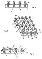
- FIG. 4 shows the main body 10 from FIG. 2 , wherein in each case a nozzle element 30 is inserted into the conical bores 12. It can be seen that each inlet port E is in contact with two channels 14/16 each, so that fluids pressed into the channels 14/16 enter the inlet ports E and are thus conveyed through the nozzle elements to the outlet ports. Due to the concave shape of the nozzle feet, the nozzle elements 30 in the conical bores 12 can be pivoted in a certain angular range in two directions, whereby the contact between inlet openings E and channels is maintained.
- FIG. 5 shows a perspective view of the base body 10 with attached nozzle elements 30 and a screwed by means of flange screws 19 on the top 10a of the base press flange 18.
- This press flange 18 extends along the edge of the top 10a and serves, as described later, the waterproof connection between the base body and a liquid foil.
- the contact surface of the press flange 18 on the upper side 10a defines the sealing plane.
- FIG. 6 how to use FIG. 6 sees, after mounting the nozzle members 30, a holding plate 20 is screwed with screws 25 to the base body 10. In this case, the holding plate 20 through openings 22, through which in each case an upper portion of the balls 32 of the nozzle elements 30 extends. The nozzle elements 30 can thus be pivoted into the desired angular position and locked by the holding plate 20. If fewer nozzle elements are to be installed than holes 12 are present, the surplus holes can be sealed by "blind balls". On such a blind ball, a neck may be arranged, the end of which carries a lamp element and / or a switch element which protrudes in the installed state (see below) just like a nozzle head into the tub.
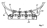
- FIG. 7 shows the installed state of the device.
- the base body 10 is located below a trough W and the nozzle necks H extend through a gap Z located between the trough bottom W and the base body 10.
- the base body 10 and trough bottom W are connected to one another via the liquid foil 40, which is pressed between the surface 10a and the press flange connected, so that the gap Z may belong to the wet area.
- Holes are arranged in the tub bottom W, through which fluid coming through the nozzle elements 30 reaches the interior of the tub.
- the flanges 36 of the nozzle members 30 abut the outside of the tub bottom while the discs 37a are on the inside of the tub bottom.
- the device can be adapted to a variety of shapes of tray bottoms, so that identical devices can be used for a variety of different wells.
Landscapes
- Health & Medical Sciences (AREA)
- Public Health (AREA)
- Epidemiology (AREA)
- Pain & Pain Management (AREA)
- Physical Education & Sports Medicine (AREA)
- Rehabilitation Therapy (AREA)
- Life Sciences & Earth Sciences (AREA)
- Animal Behavior & Ethology (AREA)
- General Health & Medical Sciences (AREA)
- Veterinary Medicine (AREA)
- Nozzles (AREA)
- Bathtub Accessories (AREA)
Description
- Die Erfindung betrifft eine Vorrichtung zur Zuführung von Fluiden zu einer Wanne nach Anspruch 1.
- In der Technik sind sogenannte Whirlpools bekannt. Im Wannenboden eines solchen Whirlpools sind Düsen vorgesehen, durch die mittels eines sich unterhalb des Wannenbodens befindenden Rohrleitungssystems ein Fluid in Form von Luft und/oder Wasser in die Wanne hineingedrückt werden kann. Dieses Rohrleitungssystem muss der jeweiligen Wannenform angepasst werden, so dass insbesondere dann, wenn eine spezielle Wannenform in nur geringen Stückzahlen hergestellt wird, der Fertigungsaufwand sehr hoch ist, was zu einem entsprechend hohen Preis führt.
- Ein bekannter Whirlpool ist in
EP 0 645 133 offenbart. - Die vorliegende Erfindung stellt sich die Aufgabe, eine Vorrichtung zu schaffen, mit deren Hilfe Fluide einer Wanne zugeführt werden können, und die sich leicht an eine individuelle Wannenform anpassen lässt.
- Diese Aufgabe wird durch eine Vorrichtung mit den Merkmalen des Anspruchs 1 gelöst.
- Die Grundidee der Erfindung besteht darin, einen Grundkörper, welcher die Düsen trägt, vollständig unterhalb des Wannenbodens anzuordnen, wobei dieser Grundkörper für eine Vielzahl von Wannen die gleiche Form haben kann. Der Grundkörper kann hierbei im den Wannenboden abstützenden Material, beispielsweise Styropor aufgenommen sein. An diesem Grundkörper sind beweglich eine Mehrzahl von Düsenelementen angeordnet, die durch geeignete Bohrungen im Boden der Wanne in diese hineinragen. Der Grundkörper weist einen Hohlraum auf, mit dem die Düsenelemente in Verbindung stehen und von dem aus sie mit dem gewünschten Fluid, also mit Wasser und/oder mit Luft versorgt werden. Die Beweglichkeit der Düsenelemente bezüglich des Grundkörpers wird dadurch erreicht, dass die Oberseite des Grundkörpers Bohrungen aufweist, in denen jeweils ein Teil eines Düsenelements, nämlich der Düsenfuß, liegt. Der Düsenfuß ist hierzu zumindest abschnittsweise konvex, insbesondere kugelförmig, ausgebildet, so dass er in einem gewissen Winkelbereich in die gewünschte Richtung orientiert werden kann. Der Düsenfuß ist mit einem Düsenkopf verbunden, der wiederum im montierten Zustand mit der Wanne, insbesondere mit dem Wannenboden verbunden ist.
- Vorzugsweise sind Düsenfuß und Düsenkopf mittels eines Düsenhalses verbunden, dessen Länge einstellbar ist.
- Die Erfindung wird nun anhand eines Ausführungsbeispiels näher erläutert. Hierbei zeigen:
-
- Figur 1
- Eine Draufsicht auf einen Grundkörper,
- Figur 2
- einen Schnitt durch den Grundkörper aus
Figur 1 entlang der Linie A-A, - Figur 3
- ein Düsenelement,
- Figur 4
- das in
Figur 2 Gezeigte mit aufgesetzten Düsenelementen, - Figur 5
- das in
Figur 4 Gezeigte in einer perspektivischen Darstellung, wobei weiterhin ein Pressflansch auf den Grundkörper aufgeschraubt ist, - Figur 6
- das in
Figur 4 Gezeigte mit aufgeschraubter Halteplatte, und - Figur 7
- die Vorrichtung aus
Figur 6 , die an einen Wannenboden angeschlossen ist. -
Figur 1 zeigt einen Grundkörper 10 in einer Draufsicht,Figur 2 zeigt einen Schnitt entlang der Linie A-A durchFigur 1 . Durch den starren Grundkörper erstrecken sich erste Kanäle 14 und zweite Kanäle 16, wobei erste Kanäle 14 und zweite Kanäle 16 senkrecht zueinander stehen und in einer Ebene liegen. Hierdurch kreuzen sich erste und zweite Kanäle, so dass sie alle mittelbar oder unmittelbar miteinander verbunden sind und ein Hohlraum im Grundkörper entsteht. Dort, wo die Kanäle 14,16 aus dem Grundkörper austreten, also an den Seitenwänden des Grundkörpers, befinden sich Anschlüsse für Leitungen (nicht dargestellt), durch diese nicht dargestellten Leitungen kann dem Hohlraum Luft oder Wasser oder beides zugeführt werden. - Dort, wo sich jeweils ein erster Kanal 14 und ein zweiter Kanal 16 schneidet, ist in der Oberseite 10a des Grundkörpers 10 eine konische Bohrung 12 angeordnet, die bis in die sich kreuzenden Kanäle reicht.
- In jede dieser Bohrung wird ein Düsenelement 30 eingesetzt, wie es in
Figur 3 dargestellt ist. Das Düsenelement 30 ist aus drei Bauteilen aufgebaut, nämlich aus der Kugel 32, durch die sich die Gewindebohrung 32a erstreckt, dem in die Gewindebohrung 32a eingeschraubten Gewinderohr 35, welches an seinem oberen Ende einen Flansch 36 trägt und dem Abschlusselement 37, welches aus einer Scheibe 37a und einem Einsteckrohr 37b besteht, welches in das Gewinderohr 35 eingesteckt ist. - Der unterste Punkt des Düsenelementes 30 ist die Einlassöffnung E, am obersten Punkt des Düsenelementes 30 befindet sich die Auslassöffnung A.
- Somit besteht das in diesem Ausführungsbeispiel aus drei Elementen aufgebaute Düsenelement 30 aus drei Abschnitten, nämlich dem Düsenfuß F, dem Düsenkopf K und dem Düsenfuß und Düsenkopf verbindenden Düsenhals H. Die Länge dieses Düsenhalses kann durch Ein- und Ausschrauben des Gewinderohres 35 in die Gewindebohrung 32a verändert werden. Je nach Einschraubtiefe des Gewinderohres 35 wird die Einlassöffnung E durch die untere Stirnseite dieses Gewinderohres 35 oder durch den unteren Austrittspunkt der Gewindebohrung 32a gebildet. Der Düsenkopf K wird durch den Flansch 36 und die Scheibe 37 gebildet.
- Die
Figur 4 zeigt den Grundkörper 10 ausFigur 2 , wobei in die konischen Bohrungen 12 jeweils ein Düsenelement 30 eingesetzt ist. Man sieht, dass jede Einlassöffnungen E in Kontakt mit je zwei Kanälen 14/16 steht, so dass Fluide, die in die Kanäle 14/16 gepresst werden, in die Eintrittsöffnungen E eintreten und so durch die Düsenelemente zu den Austrittsöffnungen gefördert werden. Aufgrund der konkaven Form der Düsenfüße können die Düsenelemente 30 in den konischen Bohrungen 12 in einem gewissen Winkelbereich in zwei Richtungen verschwenkt werden, wobei der Kontakt zwischen Einlassöffnungen E und Kanälen erhalten bleibt. -
Figur 5 zeigt eine perspektivische Darstellung des Grundkörpers 10 mit aufgesetzten Düsenelementen 30 und einem mittels Flanschschrauben 19 auf die Oberseite 10a des Grundkörpers aufgeschraubten Pressflansch 18. Dieser Pressflansch 18 erstreckt sich entlang der Kante der Oberseite 10a und dient, wie später beschrieben, der wasserdichten Verbindung zwischen Grundkörper und einer Flüssigfolie. Die Auflagefläche des Pressflansches 18 auf der Oberseite 10a definiert die Abdichtungsebene. - Wie man anhand
Figur 6 sieht, wird nach Aufsetzen der Düsenelemente 30 eine Halteplatte 20 mit Schrauben 25 auf den Grundkörper 10 aufgeschraubt. Hierbei weist die Halteplatte 20 Durchbrechungen 22 auf, durch die sich jeweils ein oberer Abschnitt der Kugeln 32 der Düsenelemente 30 erstreckt. Die Düsenelemente 30 können somit in die gewünschte Winkelposition verschwenkt und durch die Halteplatte 20 arretiert werden. Sollen weniger Düsenelemente verbaut werden, als Bohrungen 12 vorhanden sind, können die überzähligen Bohrungen durch "Blindkugeln" abgedichtet werden. An einer solche Blindkugel kann auch ein Hals angeordnet sein, dessen Ende ein Lampenelement und/oder ein Schalterelement trägt, welches in eingebautem Zustand (siehe unten) genau wie ein Düsenkopf in die Wanne hineinragt. -
Figur 7 zeigt den eingebauten Zustand der Vorrichtung. Hierbei befindet sich der Grundkörper 10 unterhalb eines Wannenbodens W und die Düsenhälse H erstrecken sich durch einen sich zwischen Wannenboden W und Grundkörper 10 befindenden Zwischenraum Z. Grundkörper 10 und Wannenboden W sind über die Flüssigfolie 40, die zwischen Oberfläche 10a und Pressflansch verpresst ist, miteinander verbunden, so dass der Zwischenraum Z zum Nassbereich gehören kann. Im Wannenboden W sind Löcher angeordnet, durch die durch die Düsenelemente 30 kommendes Fluid ins Innere der Wanne gelangt. Die Flansche 36 der Düsenelemente 30 liegen außen am Wannenboden an, während sich die Scheiben 37a auf der Innenseite des Wannenbodens befinden. - Durch die Verschwenkbarkeit der Düsenfüße und die Einstellbarkeit der Länge der Düsenhälse, lässt sich die Vorrichtung einer Vielzahl von Formen von Wannenböden anpassen, so dass für eine Vielzahl unterschiedlicher Wannen baugleiche Vorrichtungen verwendet werden können.
-
- 10
- Grundkörper
- 10a
- Oberseite
- 12
- Bohrungen
- 14
- erster Kanal
- 16
- zweiter Kanal
- 18
- Pressflansch
- 19
- Flanschschraube
- 20
- Halteplatte
- 22
- Durchbrechung
- 25
- Schraube
- 30
- Düsenelement
- 32
- Kugel
- 32a
- Gewindebohrung
- 35
- Gewinderohr
- 36
- Flansch
- 37
- Scheibe
- 40
- Flüssigfolie
- A
- Auslassöffnung
- E
- Einlassöffnung
- F
- Düsenfuß
- H
- Düsenhals
- K
- Düsenkopf
- W
- Wannenboden
Claims (10)
- Vorrichtung zur Zuführung von Fluiden zu einer Wanne bestehend aus:- einem wenigstens einen Hohlraum aufweisenden Grundkörper (10) mit einer Oberseite (10a), wobei die Oberseite eine Mehrzahl von Bohrungen (12) aufweist, die jeweils bis in den Hohlraum reichen und- Düsenelementen (30) mit einem Düsenkopf (K) und einem konvexen Düsenfuß (F), wobei der Düsenfuß (F) eine Einlassöffnung (E) und der Düsenkopf (K) eine mit der Einlassöffnung verbundene Auslassöffnung (A) aufweist, wobei- zumindest einer Bohrung (12) ein Düsenelement (30) zugeordnet ist, dessen Düsenfuß (F) auf der Bohrung (12) aufliegt und wobei- Düsenfuß (F) und Düsenkopf (K) durch einen Düsenhals (H) miteinander verbunden sind,dadurch gekennzeichnet, dass oberhalb der Oberseite (10a) des Grundkörpers (10) eine Halteplatte (20) mit Durchbrechungen (22), durch die sich die Hälse (H) der Düsenelemente erstrecken, angeordnet ist.
- Vorrichtung nach Anspruch 1, dadurch gekennzeichnet, dass der Düsenfuß (F) im wesentlichen kugelförmig ausgebildet ist.
- Vorrichtung nach Anspruch 1, dadurch gekennzeichnet, dass die Länge des Düsenhalses (H) veränderbar ist.
- Vorrichtung nach Anspruch 3, dadurch gekennzeichnet, dass das Düsenelement eine Kugel (32) mit einer Gewindebohrung (32a) und ein in die Kugel (32) eingeschraubtes Gewinderohr (35) aufweist.
- Vorrichtung nach Anspruch einem der vorangehenden Ansprüche, dadurch gekennzeichnet, dass jeder Bohrung (12) eine Durchbrechung (22) zugeordnet ist und die einander zugeordnete Bohrung und Durchbrechung eine gemeinsame Bohrachse haben.
- Vorrichtung nach einem der vorangehenden Ansprüche, dadurch gekennzeichnet, dass der Hohlraum aus einer Mehrzahl von Kanälen (14,16) besteht, die sich parallel zur Oberfläche erstrecken.
- Vorrichtung nach Anspruch 6, dadurch gekennzeichnet, dass erste und zweite Kanäle (14,16) vorhanden sind, die zueinander senkrecht stehen.
- Vorrichtung nach Anspruch 7, dadurch gekennzeichnet, dass sich am Ort einer Bohrung jeweils ein erster und ein zweiter Kanal schneiden.
- Vorrichtung nach einem der vorangehenden Ansprüche, dadurch gekennzeichnet, dass eine Mehrzahl von Düsenelementen vorhanden ist.
- Vorrichtung nach einem der vorangehenden Ansprüche, dadurch gekennzeichnet, dass auf die Oberseite (10a) des Grundkörpers (10) ein Pressflansch (18) aufgeschraubt ist.
Applications Claiming Priority (2)
| Application Number | Priority Date | Filing Date | Title |
|---|---|---|---|
| DE202005019335U DE202005019335U1 (de) | 2005-12-10 | 2005-12-10 | Vorrichtung zur Zuführung von Fluiden zu einer Wanne |
| PCT/EP2006/011585 WO2007065613A1 (de) | 2005-12-10 | 2006-12-02 | Vorrichtung zur zuführung von fluiden zu einer wanne |
Publications (2)
| Publication Number | Publication Date |
|---|---|
| EP1959910A1 EP1959910A1 (de) | 2008-08-27 |
| EP1959910B1 true EP1959910B1 (de) | 2012-03-14 |
Family
ID=35746179
Family Applications (1)
| Application Number | Title | Priority Date | Filing Date |
|---|---|---|---|
| EP06829247A Not-in-force EP1959910B1 (de) | 2005-12-10 | 2006-12-02 | Vorrichtung zur zuführung von fluiden zu einer wanne |
Country Status (4)
| Country | Link |
|---|---|
| EP (1) | EP1959910B1 (de) |
| AT (1) | ATE549007T1 (de) |
| DE (1) | DE202005019335U1 (de) |
| WO (1) | WO2007065613A1 (de) |
Family Cites Families (8)
| Publication number | Priority date | Publication date | Assignee | Title |
|---|---|---|---|---|
| GB1414203A (en) * | 1973-01-30 | 1975-11-19 | Nicollet M | Hydromassage bath installation |
| DE2919313A1 (de) * | 1979-05-14 | 1980-11-27 | Theo Kilian | Badewanne |
| DE8901137U1 (de) * | 1989-02-02 | 1989-03-16 | Fa. Franz Viegener Ii, 5952 Attendorn | Luftdüse für eine Whirlpool-Wanne |
| US5000665A (en) * | 1990-02-28 | 1991-03-19 | American Standard Inc. | Adjustable flow mini whirlpool jet |
| IT1263696B (it) * | 1993-09-27 | 1996-08-27 | Jacuzzi Europ | Vasca da bagno per idromassaggio, in particolare idromassaggio dorsale |
| US5526540A (en) * | 1995-03-31 | 1996-06-18 | American Standard Inc. | Hydrotherapy nozzle assembly |
| DE60107124T2 (de) * | 2000-01-13 | 2005-11-10 | Faiso Ltd., Tallaght | Venturistrahleinheit |
| DE102004037049A1 (de) * | 2003-08-14 | 2005-03-17 | Dse Stehle Elektronik Gmbh | Luftversorgungsvorrichtung |
-
2005
- 2005-12-10 DE DE202005019335U patent/DE202005019335U1/de not_active Expired - Lifetime
-
2006
- 2006-12-02 WO PCT/EP2006/011585 patent/WO2007065613A1/de not_active Ceased
- 2006-12-02 EP EP06829247A patent/EP1959910B1/de not_active Not-in-force
- 2006-12-02 AT AT06829247T patent/ATE549007T1/de active
Also Published As
| Publication number | Publication date |
|---|---|
| EP1959910A1 (de) | 2008-08-27 |
| ATE549007T1 (de) | 2012-03-15 |
| WO2007065613A1 (de) | 2007-06-14 |
| DE202005019335U1 (de) | 2006-01-26 |
Similar Documents
| Publication | Publication Date | Title |
|---|---|---|
| DE112017000156B4 (de) | Ein Überlochinstallationsgerät | |
| EP0023582B1 (de) | Säule für die Hochdruckflüssigkeitschromatographie und deren Verwendung | |
| EP2084451B1 (de) | Schmiermittelverteiler | |
| DE20102475U1 (de) | Kupplung zum Aneinanderfügen von zwei Kunststoffflaschen, die als Lehrmittel wiederverwendet werden | |
| DE3819305A1 (de) | Begasungseinrichtung | |
| DE202015007046U1 (de) | Wasserzuführsystem einer Flüssigkeitskühlvorrichtung, Pumpe mit Wasserzuführsystem und Flüssigkeitskühlvorrichtung mit Wasserzuführsystem | |
| DE3826064C2 (de) | ||
| EP2634318B1 (de) | Sanitärarmatur | |
| DE102017110501B4 (de) | Vorrichtung zur Bewässerung von Fahrbahnen | |
| DE102021109850A1 (de) | Dosiermodul | |
| EP1959910B1 (de) | Vorrichtung zur zuführung von fluiden zu einer wanne | |
| DE102004018144A1 (de) | Kühler für elektrische oder elektronische Bauteile, insbesondere für CPUs oder Grafikkarten sowie Düsenplatte | |
| DE102007011042B4 (de) | Verfahren zum Herstellen eines Sprühbalkens, Sprühbalken und Druckmaschine mit Sprühbalken | |
| DE4235723A1 (de) | Mehrwege-Kugelhahn | |
| DE2426469A1 (de) | Brausekopf fuer eine sanitaere brause | |
| DE1963451C3 (de) | Mischbatterie für sanitäre Anlagen | |
| DE2304658A1 (de) | Ventilkoerper-rohr-verbindungseinrichtung | |
| DE10233863A1 (de) | Anschlussblock für Sanitärarmaturen | |
| DE2512979A1 (de) | Wasserhahn, insbesondere zur befestigung auf einer sanitaeren einrichtung | |
| EP2072695B2 (de) | Unterputzspülkasten mit einem Anschlussstück zum Anschliessen einer Wasserversorgungsleitung und Verfahren zum Anschliessen eines Unterputzspülkastens an eine Wasserversorgungsleitung | |
| DE2655935C2 (de) | Aufspreizbare Vorrichtung zum Befestigen von rohrförmigen Wickelhülsen auf Spindeln | |
| DE102014100811B4 (de) | Spül- und Prüfeinheit für eine Sanitärarmatur | |
| DE202007003385U1 (de) | Mehrfach-Verteiler für Flüssigkeiten | |
| DE102004033472A1 (de) | Montageplatte zur Befestigung einer Markise an einer Hauswand mit einem Wärmedämmverbundsystem | |
| DE202023107259U1 (de) | Vorrichtung zum Anbringen an Beschlägen |
Legal Events
| Date | Code | Title | Description |
|---|---|---|---|
| PUAI | Public reference made under article 153(3) epc to a published international application that has entered the european phase |
Free format text: ORIGINAL CODE: 0009012 |
|
| 17P | Request for examination filed |
Effective date: 20080710 |
|
| AK | Designated contracting states |
Kind code of ref document: A1 Designated state(s): AT BE BG CH CY CZ DE DK EE ES FI FR GB GR HU IE IS IT LI LT LU LV MC NL PL PT RO SE SI SK TR |
|
| 17Q | First examination report despatched |
Effective date: 20090908 |
|
| GRAP | Despatch of communication of intention to grant a patent |
Free format text: ORIGINAL CODE: EPIDOSNIGR1 |
|
| GRAJ | Information related to disapproval of communication of intention to grant by the applicant or resumption of examination proceedings by the epo deleted |
Free format text: ORIGINAL CODE: EPIDOSDIGR1 |
|
| DAX | Request for extension of the european patent (deleted) | ||
| GRAP | Despatch of communication of intention to grant a patent |
Free format text: ORIGINAL CODE: EPIDOSNIGR1 |
|
| GRAS | Grant fee paid |
Free format text: ORIGINAL CODE: EPIDOSNIGR3 |
|
| GRAA | (expected) grant |
Free format text: ORIGINAL CODE: 0009210 |
|
| AK | Designated contracting states |
Kind code of ref document: B1 Designated state(s): AT BE BG CH CY CZ DE DK EE ES FI FR GB GR HU IE IS IT LI LT LU LV MC NL PL PT RO SE SI SK TR |
|
| REG | Reference to a national code |
Ref country code: GB Ref legal event code: FG4D Free format text: NOT ENGLISH |
|
| REG | Reference to a national code |
Ref country code: CH Ref legal event code: EP Ref country code: AT Ref legal event code: REF Ref document number: 549007 Country of ref document: AT Kind code of ref document: T Effective date: 20120315 |
|
| REG | Reference to a national code |
Ref country code: IE Ref legal event code: FG4D Free format text: LANGUAGE OF EP DOCUMENT: GERMAN |
|
| REG | Reference to a national code |
Ref country code: DE Ref legal event code: R096 Ref document number: 502006011135 Country of ref document: DE Effective date: 20120510 |
|
| REG | Reference to a national code |
Ref country code: NL Ref legal event code: VDEP Effective date: 20120314 |
|
| PG25 | Lapsed in a contracting state [announced via postgrant information from national office to epo] |
Ref country code: LT Free format text: LAPSE BECAUSE OF FAILURE TO SUBMIT A TRANSLATION OF THE DESCRIPTION OR TO PAY THE FEE WITHIN THE PRESCRIBED TIME-LIMIT Effective date: 20120314 |
|
| LTIE | Lt: invalidation of european patent or patent extension |
Effective date: 20120314 |
|
| PG25 | Lapsed in a contracting state [announced via postgrant information from national office to epo] |
Ref country code: FI Free format text: LAPSE BECAUSE OF FAILURE TO SUBMIT A TRANSLATION OF THE DESCRIPTION OR TO PAY THE FEE WITHIN THE PRESCRIBED TIME-LIMIT Effective date: 20120314 Ref country code: GR Free format text: LAPSE BECAUSE OF FAILURE TO SUBMIT A TRANSLATION OF THE DESCRIPTION OR TO PAY THE FEE WITHIN THE PRESCRIBED TIME-LIMIT Effective date: 20120615 Ref country code: LV Free format text: LAPSE BECAUSE OF FAILURE TO SUBMIT A TRANSLATION OF THE DESCRIPTION OR TO PAY THE FEE WITHIN THE PRESCRIBED TIME-LIMIT Effective date: 20120314 |
|
| PG25 | Lapsed in a contracting state [announced via postgrant information from national office to epo] |
Ref country code: CY Free format text: LAPSE BECAUSE OF FAILURE TO SUBMIT A TRANSLATION OF THE DESCRIPTION OR TO PAY THE FEE WITHIN THE PRESCRIBED TIME-LIMIT Effective date: 20120314 |
|
| PG25 | Lapsed in a contracting state [announced via postgrant information from national office to epo] |
Ref country code: PL Free format text: LAPSE BECAUSE OF FAILURE TO SUBMIT A TRANSLATION OF THE DESCRIPTION OR TO PAY THE FEE WITHIN THE PRESCRIBED TIME-LIMIT Effective date: 20120314 Ref country code: RO Free format text: LAPSE BECAUSE OF FAILURE TO SUBMIT A TRANSLATION OF THE DESCRIPTION OR TO PAY THE FEE WITHIN THE PRESCRIBED TIME-LIMIT Effective date: 20120314 Ref country code: SI Free format text: LAPSE BECAUSE OF FAILURE TO SUBMIT A TRANSLATION OF THE DESCRIPTION OR TO PAY THE FEE WITHIN THE PRESCRIBED TIME-LIMIT Effective date: 20120314 Ref country code: SE Free format text: LAPSE BECAUSE OF FAILURE TO SUBMIT A TRANSLATION OF THE DESCRIPTION OR TO PAY THE FEE WITHIN THE PRESCRIBED TIME-LIMIT Effective date: 20120314 Ref country code: EE Free format text: LAPSE BECAUSE OF FAILURE TO SUBMIT A TRANSLATION OF THE DESCRIPTION OR TO PAY THE FEE WITHIN THE PRESCRIBED TIME-LIMIT Effective date: 20120314 Ref country code: CZ Free format text: LAPSE BECAUSE OF FAILURE TO SUBMIT A TRANSLATION OF THE DESCRIPTION OR TO PAY THE FEE WITHIN THE PRESCRIBED TIME-LIMIT Effective date: 20120314 Ref country code: IS Free format text: LAPSE BECAUSE OF FAILURE TO SUBMIT A TRANSLATION OF THE DESCRIPTION OR TO PAY THE FEE WITHIN THE PRESCRIBED TIME-LIMIT Effective date: 20120714 |
|
| PG25 | Lapsed in a contracting state [announced via postgrant information from national office to epo] |
Ref country code: PT Free format text: LAPSE BECAUSE OF FAILURE TO SUBMIT A TRANSLATION OF THE DESCRIPTION OR TO PAY THE FEE WITHIN THE PRESCRIBED TIME-LIMIT Effective date: 20120716 Ref country code: SK Free format text: LAPSE BECAUSE OF FAILURE TO SUBMIT A TRANSLATION OF THE DESCRIPTION OR TO PAY THE FEE WITHIN THE PRESCRIBED TIME-LIMIT Effective date: 20120314 |
|
| PLBE | No opposition filed within time limit |
Free format text: ORIGINAL CODE: 0009261 |
|
| STAA | Information on the status of an ep patent application or granted ep patent |
Free format text: STATUS: NO OPPOSITION FILED WITHIN TIME LIMIT |
|
| PG25 | Lapsed in a contracting state [announced via postgrant information from national office to epo] |
Ref country code: DK Free format text: LAPSE BECAUSE OF FAILURE TO SUBMIT A TRANSLATION OF THE DESCRIPTION OR TO PAY THE FEE WITHIN THE PRESCRIBED TIME-LIMIT Effective date: 20120314 Ref country code: NL Free format text: LAPSE BECAUSE OF FAILURE TO SUBMIT A TRANSLATION OF THE DESCRIPTION OR TO PAY THE FEE WITHIN THE PRESCRIBED TIME-LIMIT Effective date: 20120314 |
|
| 26N | No opposition filed |
Effective date: 20121217 |
|
| PG25 | Lapsed in a contracting state [announced via postgrant information from national office to epo] |
Ref country code: IT Free format text: LAPSE BECAUSE OF FAILURE TO SUBMIT A TRANSLATION OF THE DESCRIPTION OR TO PAY THE FEE WITHIN THE PRESCRIBED TIME-LIMIT Effective date: 20120314 |
|
| REG | Reference to a national code |
Ref country code: DE Ref legal event code: R097 Ref document number: 502006011135 Country of ref document: DE Effective date: 20121217 |
|
| PG25 | Lapsed in a contracting state [announced via postgrant information from national office to epo] |
Ref country code: ES Free format text: LAPSE BECAUSE OF FAILURE TO SUBMIT A TRANSLATION OF THE DESCRIPTION OR TO PAY THE FEE WITHIN THE PRESCRIBED TIME-LIMIT Effective date: 20120625 |
|
| PGFP | Annual fee paid to national office [announced via postgrant information from national office to epo] |
Ref country code: GB Payment date: 20130212 Year of fee payment: 7 |
|
| BERE | Be: lapsed |
Owner name: HEUBERGER, TOBIAS Effective date: 20121231 Owner name: HEUBERGER, MARTIN Effective date: 20121231 |
|
| PG25 | Lapsed in a contracting state [announced via postgrant information from national office to epo] |
Ref country code: BG Free format text: LAPSE BECAUSE OF FAILURE TO SUBMIT A TRANSLATION OF THE DESCRIPTION OR TO PAY THE FEE WITHIN THE PRESCRIBED TIME-LIMIT Effective date: 20120614 Ref country code: MC Free format text: LAPSE BECAUSE OF NON-PAYMENT OF DUE FEES Effective date: 20121231 |
|
| REG | Reference to a national code |
Ref country code: IE Ref legal event code: MM4A |
|
| PG25 | Lapsed in a contracting state [announced via postgrant information from national office to epo] |
Ref country code: BE Free format text: LAPSE BECAUSE OF NON-PAYMENT OF DUE FEES Effective date: 20121231 |
|
| PG25 | Lapsed in a contracting state [announced via postgrant information from national office to epo] |
Ref country code: IE Free format text: LAPSE BECAUSE OF NON-PAYMENT OF DUE FEES Effective date: 20121202 |
|
| PG25 | Lapsed in a contracting state [announced via postgrant information from national office to epo] |
Ref country code: TR Free format text: LAPSE BECAUSE OF FAILURE TO SUBMIT A TRANSLATION OF THE DESCRIPTION OR TO PAY THE FEE WITHIN THE PRESCRIBED TIME-LIMIT Effective date: 20120314 |
|
| PG25 | Lapsed in a contracting state [announced via postgrant information from national office to epo] |
Ref country code: HU Free format text: LAPSE BECAUSE OF FAILURE TO SUBMIT A TRANSLATION OF THE DESCRIPTION OR TO PAY THE FEE WITHIN THE PRESCRIBED TIME-LIMIT Effective date: 20061202 |
|
| GBPC | Gb: european patent ceased through non-payment of renewal fee |
Effective date: 20131202 |
|
| PG25 | Lapsed in a contracting state [announced via postgrant information from national office to epo] |
Ref country code: GB Free format text: LAPSE BECAUSE OF NON-PAYMENT OF DUE FEES Effective date: 20131202 |
|
| PG25 | Lapsed in a contracting state [announced via postgrant information from national office to epo] |
Ref country code: LU Free format text: LAPSE BECAUSE OF NON-PAYMENT OF DUE FEES Effective date: 20141202 |
|
| REG | Reference to a national code |
Ref country code: CH Ref legal event code: PL |
|
| REG | Reference to a national code |
Ref country code: AT Ref legal event code: MM01 Ref document number: 549007 Country of ref document: AT Kind code of ref document: T Effective date: 20141202 |
|
| REG | Reference to a national code |
Ref country code: FR Ref legal event code: ST Effective date: 20150831 |
|
| REG | Reference to a national code |
Ref country code: FR Ref legal event code: PLFP Year of fee payment: 10 |
|
| PG25 | Lapsed in a contracting state [announced via postgrant information from national office to epo] |
Ref country code: CH Free format text: LAPSE BECAUSE OF NON-PAYMENT OF DUE FEES Effective date: 20141231 Ref country code: LI Free format text: LAPSE BECAUSE OF NON-PAYMENT OF DUE FEES Effective date: 20141231 |
|
| REG | Reference to a national code |
Ref country code: CH Ref legal event code: NV Representative=s name: PATENTANWAELTE KLEIN AND KLEIN, CH Ref country code: CH Ref legal event code: AECN Free format text: DAS PATENT IST AUFGRUND DES WEITERBEHANDLUNGSANTRAGS VOM 29. SEPTEMBER 2015 REAKTIVIERT WORDEN. |
|
| REG | Reference to a national code |
Ref country code: FR Ref legal event code: RN Effective date: 20151029 |
|
| PG25 | Lapsed in a contracting state [announced via postgrant information from national office to epo] |
Ref country code: AT Free format text: LAPSE BECAUSE OF NON-PAYMENT OF DUE FEES Effective date: 20141202 Ref country code: FR Free format text: LAPSE BECAUSE OF NON-PAYMENT OF DUE FEES Effective date: 20141231 |
|
| REG | Reference to a national code |
Ref country code: FR Ref legal event code: FC Effective date: 20151112 |
|
| PGRI | Patent reinstated in contracting state [announced from national office to epo] |
Ref country code: CH Effective date: 20151030 Ref country code: LI Effective date: 20151030 |
|
| PGRI | Patent reinstated in contracting state [announced from national office to epo] |
Ref country code: FR Effective date: 20151218 |
|
| REG | Reference to a national code |
Ref country code: AT Ref legal event code: NFJG Ref document number: 549007 Country of ref document: AT Kind code of ref document: T Effective date: 20160801 |
|
| REG | Reference to a national code |
Ref country code: FR Ref legal event code: PLFP Year of fee payment: 11 |
|
| PGFP | Annual fee paid to national office [announced via postgrant information from national office to epo] |
Ref country code: CH Payment date: 20161221 Year of fee payment: 11 Ref country code: LU Payment date: 20161227 Year of fee payment: 11 Ref country code: DE Payment date: 20161213 Year of fee payment: 11 |
|
| PGFP | Annual fee paid to national office [announced via postgrant information from national office to epo] |
Ref country code: AT Payment date: 20161222 Year of fee payment: 11 Ref country code: FR Payment date: 20161222 Year of fee payment: 11 |
|
| REG | Reference to a national code |
Ref country code: DE Ref legal event code: R119 Ref document number: 502006011135 Country of ref document: DE |
|
| REG | Reference to a national code |
Ref country code: CH Ref legal event code: PL |
|
| REG | Reference to a national code |
Ref country code: AT Ref legal event code: MM01 Ref document number: 549007 Country of ref document: AT Kind code of ref document: T Effective date: 20171202 |
|
| PG25 | Lapsed in a contracting state [announced via postgrant information from national office to epo] |
Ref country code: LU Free format text: LAPSE BECAUSE OF NON-PAYMENT OF DUE FEES Effective date: 20171202 |
|
| REG | Reference to a national code |
Ref country code: FR Ref legal event code: ST Effective date: 20180831 |
|
| PG25 | Lapsed in a contracting state [announced via postgrant information from national office to epo] |
Ref country code: FR Free format text: LAPSE BECAUSE OF NON-PAYMENT OF DUE FEES Effective date: 20180102 Ref country code: DE Free format text: LAPSE BECAUSE OF NON-PAYMENT OF DUE FEES Effective date: 20180703 |
|
| PG25 | Lapsed in a contracting state [announced via postgrant information from national office to epo] |
Ref country code: LI Free format text: LAPSE BECAUSE OF NON-PAYMENT OF DUE FEES Effective date: 20171231 Ref country code: AT Free format text: LAPSE BECAUSE OF NON-PAYMENT OF DUE FEES Effective date: 20171202 Ref country code: CH Free format text: LAPSE BECAUSE OF NON-PAYMENT OF DUE FEES Effective date: 20171231 |