EP1961230B1 - Charge adaptative pour alimentation de bloc lnb de satellite - Google Patents
Charge adaptative pour alimentation de bloc lnb de satellite Download PDFInfo
- Publication number
- EP1961230B1 EP1961230B1 EP05854045.1A EP05854045A EP1961230B1 EP 1961230 B1 EP1961230 B1 EP 1961230B1 EP 05854045 A EP05854045 A EP 05854045A EP 1961230 B1 EP1961230 B1 EP 1961230B1
- Authority
- EP
- European Patent Office
- Prior art keywords
- tone
- lnb
- block
- adaptive load
- current
- Prior art date
- Legal status (The legal status is an assumption and is not a legal conclusion. Google has not performed a legal analysis and makes no representation as to the accuracy of the status listed.)
- Expired - Lifetime
Links
Images


Classifications
-
- H—ELECTRICITY
- H04—ELECTRIC COMMUNICATION TECHNIQUE
- H04H—BROADCAST COMMUNICATION
- H04H20/00—Arrangements for broadcast or for distribution combined with broadcast
- H04H20/44—Arrangements characterised by circuits or components specially adapted for broadcast
- H04H20/46—Arrangements characterised by circuits or components specially adapted for broadcast specially adapted for broadcast systems covered by groups H04H20/53-H04H20/95
- H04H20/51—Arrangements characterised by circuits or components specially adapted for broadcast specially adapted for broadcast systems covered by groups H04H20/53-H04H20/95 specially adapted for satellite broadcast systems
-
- H—ELECTRICITY
- H04—ELECTRIC COMMUNICATION TECHNIQUE
- H04N—PICTORIAL COMMUNICATION, e.g. TELEVISION
- H04N7/00—Television systems
- H04N7/20—Adaptations for transmission via a GHz frequency band, e.g. via satellite
-
- H—ELECTRICITY
- H04—ELECTRIC COMMUNICATION TECHNIQUE
- H04B—TRANSMISSION
- H04B1/00—Details of transmission systems, not covered by a single one of groups H04B3/00 - H04B13/00; Details of transmission systems not characterised by the medium used for transmission
- H04B1/06—Receivers
- H04B1/16—Circuits
- H04B1/1607—Supply circuits
-
- H—ELECTRICITY
- H04—ELECTRIC COMMUNICATION TECHNIQUE
- H04B—TRANSMISSION
- H04B1/00—Details of transmission systems, not covered by a single one of groups H04B3/00 - H04B13/00; Details of transmission systems not characterised by the medium used for transmission
- H04B1/06—Receivers
- H04B1/16—Circuits
- H04B1/18—Input circuits, e.g. for coupling to an antenna or a transmission line
-
- H—ELECTRICITY
- H04—ELECTRIC COMMUNICATION TECHNIQUE
- H04N—PICTORIAL COMMUNICATION, e.g. TELEVISION
- H04N5/00—Details of television systems
- H04N5/63—Generation or supply of power specially adapted for television receivers
Definitions
- the present invention relates generally to satellite receivers and set top boxes in satellite systems. More specifically, the invention relates to a method and apparatus for providing an adaptive load for a satellite low noise block (“LNB”) power supply.
- LNB satellite low noise block
- each "satellite" is actually a constellation of two closely spaced satellites.
- Each of these satellites comprise a number of transmitters, called transponders, each transponder of which transmits signals on a discrete RF frequency to earth-bound receivers.
- Each transponder's signal may be modulated with an audio/video program or with other data information.
- the transponders on one satellite of a constellation transmit signals with right-hand circular polarization while the transponders of the other satellite of the constellation transmit signals with left-hand circular polarization.
- Satellite receiving systems contain one or more receiving antennae, each of which is switchable to receive either right-hand or left-hand polarized signals.
- LNB low noise block
- Satellite receiver systems typically remotely power low noise blocks ('LNB") and/or RF switching devices by supplying a DC voltage.
- a 600 millivolt peak-to-peak, 22kHz tone may be superimposed on the DC voltage to enable the receiver to communicate with such devices or to select various satellite configurations.
- the presence or absence of the tone may select a particular LNB in a multi-LNB system, and the value of DC voltage supplied to the LNB may select a particular polarization.
- Satellite receiver systems having LNB power supplies with the ability to superimpose a 22kHz tone on the output are often configured with a linear pass element.
- the linear pass element typically has an emitter follower circuit that produces an undesired waveform when connected to a highly capacitive load.
- the resulting circuit acts like a peak detector causing the output voltage to stay at a value close to the maximum peak level.
- emitter follower circuits do not have the ability to remove charge from the external capacitance without the aid of some current sinking device.
- Satellite receiver systems specified a 30ma minimum current on LNB/Switching devices and a maximum of 750nF of capacitance on the output of the supply.
- Conventional designs have supplemented the minimum 30ma current with a simple resistor in the satellite receiver power supply to provide enough current sink and produce a proper 22kHz waveform shape.
- Satellite receiver systems are now moving toward a specification of zero load current at the LNB/Switch. This low load does not supply enough sinking current to produce a proper 22kHz wave shape with the 750nF load. Therefore, a method and apparatus that preserves a proper waveform in newer systems is desirable.
- US patent 4,542,300 describes a method for a power supply adaptation of a satellite LNB and a respective control apparatus in accordance with the preamble of claims 1.
- the invention is as set out in claim 1.
- FIG. 1 an exemplary satellite receiver system in accordance with one embodiment of the present invention is shown and generally designated by the reference numeral 10.
- FIG. 1 shows an LNB unit 12 located inside a satellite dish 14.
- the LNB unit 12 may comprise one or more LNBs. Each LNB may be configured to receive the signal of a different constellation of satellites.
- Each LNB of the LNB unit 12 is electrically coupled with a set top box 16.
- the set top box 16 is shown having an LNB power supply 20, a control circuit 18 and a tuner 19.
- the set top box 16 is configured to communicate with the LNB using "High” and “Low” voltage signals in combination with the presence or absence of a 22kHz tone.
- the set top box 16 may cause the LNB power supply 20 to superimpose a 22kHz tone on an output voltage from the LNB power supply 20.
- the presence or absence of the tone indicates which LNB 12 has been selected, and thus which constellation of satellite signals will be received.
- the output voltage level of the LNB power supply 20 indicates the selection of polarization.
- the set top box 16 via the LNB power supply 20 may supply a high output voltage, such as 18 volts, or a low output voltage, such as 13 volts, to indicate to the LNB to tune a signal having a particular polarization.
- the polarization may be either right- or left-handed circular polarization.
- Alternative embodiments of the invention may employ horizontal and vertical polarization or the like.
- the use of polarization allows selection of an input signal from different sets of transponders on a particular satellite constellation.
- the signal received from each transponder may comprise unique information such as different channels of audio and video programming.
- a "high" voltage level of 18 volts selects data received from a first set of transponders while a "low" signal of 13 volts selects data received from a second set of transponders.
- the set top box 16 may be configured to communicate with the LNB according to a DiSEqC standard.
- the DiSEqC standard recognizes the utilization of various voltage levels as well as the tones.
- pulse width keying of the tones is implemented in order to facilitate communication between the LNB and the set top box.
- Load conditions typically range from 0 to 450ma and are at times required to drive capacitive loads up to 750nF.
- 50ma of load is desirable to provide the proper waveform shape of an LNB power supply driving a max-specified 750nF capacitive load.
- the current sink must be adaptable to sink 50ma in both modes.
- a control circuit 18 may be adapted to provide control signals to the LNB power supply 20.
- the control signals from the control circuit enable or disable the adaptive load to sink 50 ma of current and preserve the waveform shape of a 22 kHz tone when driving highly capacitive loads with little or no additional current load.
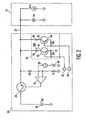
- FIG. 2 shows an exemplary LNB power supply with an adaptive load for a satellite receiver in accordance with one embodiment of the present invention and is generally designated by the reference numeral 30.
- FIG. 2 shows a power transistor 28 configured as an emitter follower circuit.
- a DC source 38 provides the high or low output voltage level discussed previously to facilitate transponder selection.
- the 22kHz tone may be superimposed by an AC source 36, depending on which LNB is required to satisfy the viewing channel to be selected by a user.
- the high or low output voltage with or without the 22kHz tone superimposed is delivered to an operational amplifier 34 to the base of the power transistor 28.
- the emitter of the power transistor 28 is connected to the bus 22 between the set top box 16 and the LNB unit 12.
- an adaptive load 40 is electrically coupled to the bus 22.
- the adaptive load 40 acts as a current sink to discharge excess charge and ensure a proper 22kHz tone waveform.
- the adaptive load comprises a high current segment 42 and a low current segment 44.
- the high current segment 42 is enabled by a high current adaptive load signal 48. When a 22kHz tone is superimposed on an 18 volt signal, the high current signal from the control circuit 18 enables the high current segment 42.
- the high current segment 42 draws 50ma through a 360 ohm resistor 46 when enabled while an 18 volt signal is present.
- the low current segment 44 is enabled by a low current adaptive load signal 52 from the control circuit 18.
- the low current adaptive load signal enables the low current segment 44 when a 22kHz tone is superimposed on a 13 volt signal.
- the low current segment 44 draws 13ma through a 1 K ohm resistor 50.
- the high current segment 42 is also enabled while a 22kHz tone is superimposed on a 13 volt signal and draws 36ma. Together, the high and low current segments can draw 49ma.
- the adaptive load is made up of two bipolar transistor switched resistive loads 46 and 50.
- the "high” load 42 provides 50ma in the 18 volt mode and 36ma when in the 13 volt mode.
- the "low” load 44 only operates in the 13 volt mode and provides 13ma of current when active. The additional 13ma of current brings the total adaptive load current to 49ma in the 13 volt mode.
- a high current adaptive load control signal 48 is used to activate the "high" load 42.
- the low current adaptive load control signal 52 is used to activate the "low" load 44.
- FIG. 3 is an exemplary power supply with an independent current source for a satellite receiver in accordance with a technical example and is generally designated by the reference numeral 60.
- the power supply 60 is different from the power supply 30 of FIG. 2 in that it implements a single current source. Also, the current source of power supply 60 is independent from the bus voltage, whereas in the power source 30 of FIG. 2 , the current drawn through the two load resistors 46 and 50 is a function of the bus voltage. In the power source 60 of FIG. 3 when the transistor 62 is "on” a constant current of 50ma is drawn through the current sink independent of the bus voltage.
- the adaptively controlled loads described above provide cost-effective solutions to preserve the 22kHz tone while minimizing the additional current required by the LNB power supply and result in overall power savings to the system.
- the system is capable of reducing channel change time. Delays associated with long "high output voltage” to "low output voltage” transition times contribute to the time it takes to switch polarization control voltage and relock the tuner 19. Satellite receiver decoders potentially require different polarization selection when transitioning from one display channel to another. In the case of polarization changes, the voltage supplied from the LNB power supply will change from "high output voltage” to "low output voltage” or vice versa.
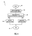
- FIG. 4 a flow chart illustrating an exemplary technique in accordance with one technical example is shown and generally designated by the reference numeral 80.
- the exemplary technique 80 begins at block 82 with the initialization of a satellite receiver.
- an LNB power supply outputs a signal, as shown at block 84.
- the signal is used for communication between the set top box 16 ( FIG. 1 ) and an LNB unit 12 ( FIG. 1 ).
- the signal may comprise multiple voltage levels as well as a superimposed 22 kHz selection tone that may be modulated.
- the adaptive load is activated, as shown at block 88. If no tone is present and there is no transition from high to low voltage, the adaptive load is deactivated because it is not needed, as illustrated at block 90.
- the technique 80 therefore, provides a method for preserving the tone waveform and potentially increases channel changing speed in the system.
- the exemplary process ends.
- the technique 80 may result in decreased power consumption, thus providing an additional benefit.
- Increased industry pressure to provide power savings militates in favor of a load that is capable of being reduced or turned off when no tone is required or when in standby mode.
- the current sink is capable of being turned off when it is not needed, for example, when there is no 22 kHz tone.
- the current sink is dependent on the bus from the power supply to the LNB, as explained in detail above. If there is no current on the bus, such as in a turned off state, there is no current drawn to the current sink.
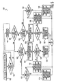
- FIG. 5 is a flow chart illustrating an exemplary technique in accordance with an alternative technical example and is generally designated by the reference numeral 100.
- the exemplary example illustrated in FIG. 5 may be implemented by the control circuit 18 ( FIG. 1 ) to take into account present tone, next tone, present voltage and next voltage conditions to determine the application of an adaptive load.
- the technique 100 accomplishes control of the two switched loads that make up the adaptive load and provides the advantages described above.
- the process begins at block 102..
- decision block 104 an initial determination is made regarding whether the next state of the tone is on or off. If the tone is off in the next state, then the tone will be turned off, as indicated at block 106. If, alternatively, the next tone state is on, process flow continues to decision block 108, where the present output voltage (low or high) is determined. If the present output voltage is low, the next output voltage state is determined, as illustrated at block 110. If the system is to remain in a low output voltage state, the next tone state (on or off), is determined at decision block 112.
- both the present output voltage (block 108) and the next output voltage states (block 110) are low and the next tone state is on, then both the high current adaptive load and the low current adaptive load are enabled and the tone is turned on, as illustrated at block 114. If, however, the next tone state is off (block 112), then the tone is turned off and both the high current adaptive load and the low current adaptive load are disabled, as indicated at block 116.
- next output voltage state is high (block 110)
- the low current adaptive load is disabled and the output voltage is set to high, as illustrated at block 120.
- decision block 122 the next tone state is determined. If the next tone state is off, the tone is turned off, and both the high current adaptive load and low current adaptive load are disabled, as indicated at block 116. If, however, the next tone state is on at block 122, the high current adaptive load is enabled prior to turning the tone on, as indicated at block 124.
- next output voltage state is determined at block 126. If the next output voltage is low at block 126, only the high current adaptive load is enabled and the output voltage is set to low, as illustrated at block 128. Process flow then continues to block 130, where the next tone state is determined. If in next state the tone is on, the low current adaptive load is enabled prior to turning the tone on, as illustrated at block 132. If, alternatively, the next tone state is off at block 130, the tone is turned off and both the high current adaptive load and the low current adaptive load are disabled, as shown at block 136.
- next tone state is determined at block 134. If the next tone state is off, the tone is turned off and both the high current adaptive load and the low current adaptive load are disabled, as indicated at block 136. If, alternatively, the next tone state is determined to be on at block 134, the high current adaptive load is enabled while the low current adaptive load is disabled prior to the tone being turned on, as indicated at block 138. At block 118, process flow ends.
Landscapes
- Engineering & Computer Science (AREA)
- Signal Processing (AREA)
- Computer Networks & Wireless Communication (AREA)
- Physics & Mathematics (AREA)
- Astronomy & Astrophysics (AREA)
- General Physics & Mathematics (AREA)
- Multimedia (AREA)
- Input Circuits Of Receivers And Coupling Of Receivers And Audio Equipment (AREA)
- Radio Relay Systems (AREA)
- Direct Current Feeding And Distribution (AREA)
Claims (1)
- Un système comprenant :un circuit de communication (30) adapté afin de fournir un signal de commande à sélectionner entre une première pluralité de signaux ou une seconde pluralité de signaux, ledit signal de commande communiquant avec ladite sélection en présentant un premier niveau DC ou un second niveau CC ;une charge adaptative (40) configurée pour alimenter un courant de charge quand ledit signal de commande effectue une transition dudit premier niveau CC audit second niveau CC ; caractérisé en ce quela charge adaptative (40) comprend un écoulement de courant bas (44) et un écoulement de courant haut (42),ledit premier niveau CC est plus élevé que ledit second niveau CC,quand une fréquence est superposée sur ledit signal de commande présentant le premier niveau CC plus élevé, seul l'écoulement de courant haut (42) est activé, et quand ledit premier niveau CC plus élevé effectue une transition vers ledit second niveau CC quand ladite fréquence existe, l'écoulement de courant bas (42) est aussi activé.
Applications Claiming Priority (1)
| Application Number | Priority Date | Filing Date | Title |
|---|---|---|---|
| PCT/US2005/045258 WO2007070042A1 (fr) | 2005-12-14 | 2005-12-14 | Charge adaptative pour alimentation de bloc lnb de satellite |
Publications (2)
| Publication Number | Publication Date |
|---|---|
| EP1961230A1 EP1961230A1 (fr) | 2008-08-27 |
| EP1961230B1 true EP1961230B1 (fr) | 2013-06-12 |
Family
ID=35985286
Family Applications (1)
| Application Number | Title | Priority Date | Filing Date |
|---|---|---|---|
| EP05854045.1A Expired - Lifetime EP1961230B1 (fr) | 2005-12-14 | 2005-12-14 | Charge adaptative pour alimentation de bloc lnb de satellite |
Country Status (7)
| Country | Link |
|---|---|
| US (1) | US7970341B2 (fr) |
| EP (1) | EP1961230B1 (fr) |
| JP (1) | JP4785934B2 (fr) |
| KR (1) | KR101225214B1 (fr) |
| CN (1) | CN101253716B (fr) |
| BR (1) | BRPI0520480B1 (fr) |
| WO (1) | WO2007070042A1 (fr) |
Families Citing this family (13)
| Publication number | Priority date | Publication date | Assignee | Title |
|---|---|---|---|---|
| GB0402131D0 (en) | 2004-01-30 | 2004-03-03 | Isis Innovation | Delivery method |
| US8549565B2 (en) | 2005-04-01 | 2013-10-01 | The Directv Group, Inc. | Power balancing signal combiner |
| US7937732B2 (en) * | 2005-09-02 | 2011-05-03 | The Directv Group, Inc. | Network fraud prevention via registration and verification |
| US8789115B2 (en) * | 2005-09-02 | 2014-07-22 | The Directv Group, Inc. | Frequency translation module discovery and configuration |
| CN101502116A (zh) | 2006-06-09 | 2009-08-05 | 直视集团公司 | 用于各种格式位流的呈现模式 |
| US20080120655A1 (en) * | 2006-11-22 | 2008-05-22 | The Directv Group, Inc. | Integrated satellite master antenna television unit |
| US9942618B2 (en) | 2007-10-31 | 2018-04-10 | The Directv Group, Inc. | SMATV headend using IP transport stream input and method for operating the same |
| TWI458241B (zh) * | 2011-09-23 | 2014-10-21 | Richtek Technology Corp | 具動態壓降控制的電源供應器及其方法 |
| US8891216B2 (en) | 2012-04-25 | 2014-11-18 | Apple Inc. | Techniques for detecting removal of a connector |
| US8724281B2 (en) | 2012-04-25 | 2014-05-13 | Apple Inc. | Techniques for detecting removal of a connector |
| AU2013200705B2 (en) * | 2012-04-25 | 2014-09-04 | Apple Inc. | Techniques for detecting removal of a connector |
| CN104348500B (zh) * | 2013-08-05 | 2016-08-31 | 启碁科技股份有限公司 | 卫星接收器 |
| US9635420B2 (en) * | 2013-11-07 | 2017-04-25 | Echostar Technologies L.L.C. | Energy saving set top box |
Family Cites Families (20)
| Publication number | Priority date | Publication date | Assignee | Title |
|---|---|---|---|---|
| US2542300A (en) * | 1949-02-03 | 1951-02-20 | Bagnato Vito | Convertible jacket |
| JPS5933337U (ja) | 1982-08-25 | 1984-03-01 | デイエツクスアンテナ株式会社 | 高周波信号切換スイツチ |
| EP0491068A1 (fr) * | 1990-12-18 | 1992-06-24 | International Business Machines Corporation | Adaptateur récepteur de diffusion de données sélectives pour des ordinateurs personnels |
| GB2280076B (en) * | 1991-02-22 | 1995-06-21 | Amstrad Plc | Improvements relating to television receivers |
| US5507025A (en) * | 1993-11-02 | 1996-04-09 | Winegard Company | Method and apparatus for satellite receiver with variable predetection bandwidth |
| KR0141742B1 (ko) * | 1995-04-26 | 1998-07-01 | 구자홍 | 멀티 엘엔비용 전원 자동선택 공급장치 |
| EP0815686A4 (fr) * | 1996-01-16 | 2000-08-16 | Hughes Electronics Corp | Carte de peripherique pour ordinateur recevant des informations transmises par satellite |
| US5970386A (en) * | 1997-01-27 | 1999-10-19 | Hughes Electronics Corporation | Transmodulated broadcast delivery system for use in multiple dwelling units |
| US5861855A (en) * | 1997-02-03 | 1999-01-19 | Hughes Electronics Corporation | Method and apparatus for de-icing a satellite dish antenna |
| JP3791249B2 (ja) | 1999-07-12 | 2006-06-28 | 株式会社日立製作所 | 携帯端末 |
| US7203457B1 (en) * | 1999-07-19 | 2007-04-10 | Thomson Licensing | Tuning system for achieving rapid signal acquisition for a digital satellite receiver |
| JP3653215B2 (ja) * | 1999-10-01 | 2005-05-25 | シャープ株式会社 | 衛星放送受信システム、ならびに衛星放送受信システムで用いられるローノイズブロックダウンコンバータおよび衛星放送受信機 |
| JP3600765B2 (ja) | 1999-10-29 | 2004-12-15 | シャープ株式会社 | 受信装置 |
| US7207054B1 (en) * | 1999-11-17 | 2007-04-17 | Allegro Microsystems, Inc. | Low noise block supply and control voltage regulator |
| JP4170552B2 (ja) * | 2000-02-15 | 2008-10-22 | マスプロ電工株式会社 | 受信状態表示装置 |
| US7130576B1 (en) * | 2001-11-07 | 2006-10-31 | Entropic Communications, Inc. | Signal selector and combiner for broadband content distribution |
| JP2003204278A (ja) * | 2002-01-07 | 2003-07-18 | Sharp Corp | 衛星放送受信用コンバータ |
| US6996389B2 (en) * | 2002-04-03 | 2006-02-07 | Thomson Licensing | Power supply for a satellite receiver |
| JP4363938B2 (ja) | 2003-09-26 | 2009-11-11 | シャープ株式会社 | 受信装置 |
| TWI336591B (en) * | 2007-05-22 | 2011-01-21 | Mstar Semiconductor Inc | Digital video broadcasting-satellite multi-input receiving circuit and associated receving method thereof |
-
2005
- 2005-12-14 EP EP05854045.1A patent/EP1961230B1/fr not_active Expired - Lifetime
- 2005-12-14 US US11/989,511 patent/US7970341B2/en active Active
- 2005-12-14 WO PCT/US2005/045258 patent/WO2007070042A1/fr not_active Ceased
- 2005-12-14 JP JP2008545550A patent/JP4785934B2/ja not_active Expired - Fee Related
- 2005-12-14 CN CN2005800511932A patent/CN101253716B/zh not_active Expired - Lifetime
- 2005-12-14 KR KR1020087002239A patent/KR101225214B1/ko not_active Expired - Lifetime
- 2005-12-14 BR BRPI0520480-1A patent/BRPI0520480B1/pt active IP Right Grant
Also Published As
| Publication number | Publication date |
|---|---|
| KR20080075831A (ko) | 2008-08-19 |
| US20090125970A1 (en) | 2009-05-14 |
| BRPI0520480A2 (pt) | 2009-05-12 |
| BRPI0520480B1 (pt) | 2019-05-07 |
| KR101225214B1 (ko) | 2013-01-22 |
| CN101253716A (zh) | 2008-08-27 |
| JP4785934B2 (ja) | 2011-10-05 |
| CN101253716B (zh) | 2012-02-08 |
| EP1961230A1 (fr) | 2008-08-27 |
| JP2009519675A (ja) | 2009-05-14 |
| WO2007070042A1 (fr) | 2007-06-21 |
| US7970341B2 (en) | 2011-06-28 |
Similar Documents
| Publication | Publication Date | Title |
|---|---|---|
| EP1961230B1 (fr) | Charge adaptative pour alimentation de bloc lnb de satellite | |
| EP1512221B1 (fr) | Systeme d'amplification de puissance a ameliorations d'alimentation et de polarisation | |
| US8063997B2 (en) | Integrated programmable tuner | |
| US6424225B1 (en) | Power amplifier circuit for providing constant bias current over a wide temperature range | |
| US8805274B2 (en) | Frequency translation module interface | |
| US20040175009A1 (en) | Data transmission device for hearing aids | |
| US9543896B2 (en) | Multiple-input multiple-output low-noise block downconverter and low-noise module | |
| US7245180B2 (en) | Intelligent RF power control for wireless modem devices | |
| WO2002023747A2 (fr) | Performance d'un systeme servant de commande retroactive de la consommation d'energie d'un recepteur numerique fonctionnant en mode veille | |
| EP1941731B1 (fr) | Impedance adaptative pour l'alimentation d'un lnb en fonction d'un protocole de communication | |
| US20030076880A1 (en) | Method and circuit for controlling switching frequency signal | |
| US10389453B2 (en) | Multiplexed RFAGC for frequency diversity receivers | |
| US20100130157A1 (en) | Rf isolation of low cost switch using shunt diode | |
| KR101989301B1 (ko) | 전원 오프상태에서 루프 스루 동작하는 셋톱박스 및 그 동작방법 | |
| US7250817B2 (en) | Linear power efficient radio frequency (RF) driver system and method with power level control | |
| US20060152278A1 (en) | Apparatus for controlling modulation of an alternating waveform on a DC voltage signal within a low-noise block controller | |
| KR100710332B1 (ko) | 디지털멀티미디어방송 단말기 | |
| KR960015275B1 (ko) | 라스트 채널 튜닝방법 | |
| JP2010020381A (ja) | Rfidリーダ装置 | |
| KR20110060206A (ko) | 고주파 대역(hf) 무선인식(rfid) 초소형 송수신기 | |
| EP1349275A2 (fr) | Circuit intégré | |
| JPH1131985A (ja) | Bs・csブースタ | |
| KR20030055428A (ko) | 두 입력을 갖는 고주파 모듈레이터 | |
| JP2006333357A (ja) | 受信装置 | |
| JPH08330995A (ja) | 衛星放送受信装置 |
Legal Events
| Date | Code | Title | Description |
|---|---|---|---|
| PUAI | Public reference made under article 153(3) epc to a published international application that has entered the european phase |
Free format text: ORIGINAL CODE: 0009012 |
|
| 17P | Request for examination filed |
Effective date: 20080208 |
|
| AK | Designated contracting states |
Kind code of ref document: A1 Designated state(s): DE FR GB |
|
| RBV | Designated contracting states (corrected) |
Designated state(s): DE FR GB |
|
| 17Q | First examination report despatched |
Effective date: 20090928 |
|
| RAP1 | Party data changed (applicant data changed or rights of an application transferred) |
Owner name: THOMSON LICENSING |
|
| DAX | Request for extension of the european patent (deleted) | ||
| REG | Reference to a national code |
Ref country code: DE Ref legal event code: R079 Ref document number: 602005040002 Country of ref document: DE Free format text: PREVIOUS MAIN CLASS: H04N0007200000 Ipc: H04H0020510000 |
|
| RIC1 | Information provided on ipc code assigned before grant |
Ipc: H04B 1/18 20060101ALI20121121BHEP Ipc: H04H 20/51 20080101AFI20121121BHEP Ipc: H04B 1/16 20060101ALI20121121BHEP |
|
| GRAP | Despatch of communication of intention to grant a patent |
Free format text: ORIGINAL CODE: EPIDOSNIGR1 |
|
| GRAS | Grant fee paid |
Free format text: ORIGINAL CODE: EPIDOSNIGR3 |
|
| GRAA | (expected) grant |
Free format text: ORIGINAL CODE: 0009210 |
|
| AK | Designated contracting states |
Kind code of ref document: B1 Designated state(s): DE FR GB |
|
| REG | Reference to a national code |
Ref country code: GB Ref legal event code: FG4D |
|
| REG | Reference to a national code |
Ref country code: GB Ref legal event code: 746 Effective date: 20130617 |
|
| REG | Reference to a national code |
Ref country code: DE Ref legal event code: R096 Ref document number: 602005040002 Country of ref document: DE Effective date: 20130808 |
|
| PLBE | No opposition filed within time limit |
Free format text: ORIGINAL CODE: 0009261 |
|
| STAA | Information on the status of an ep patent application or granted ep patent |
Free format text: STATUS: NO OPPOSITION FILED WITHIN TIME LIMIT |
|
| 26N | No opposition filed |
Effective date: 20140313 |
|
| REG | Reference to a national code |
Ref country code: DE Ref legal event code: R097 Ref document number: 602005040002 Country of ref document: DE Effective date: 20140313 |
|
| REG | Reference to a national code |
Ref country code: FR Ref legal event code: PLFP Year of fee payment: 11 |
|
| REG | Reference to a national code |
Ref country code: FR Ref legal event code: PLFP Year of fee payment: 12 |
|
| REG | Reference to a national code |
Ref country code: DE Ref legal event code: R082 Ref document number: 602005040002 Country of ref document: DE Representative=s name: DEHNS, DE Ref country code: DE Ref legal event code: R082 Ref document number: 602005040002 Country of ref document: DE Representative=s name: DEHNS PATENT AND TRADEMARK ATTORNEYS, DE Ref country code: DE Ref legal event code: R082 Ref document number: 602005040002 Country of ref document: DE Representative=s name: HOFSTETTER, SCHURACK & PARTNER PATENT- UND REC, DE |
|
| REG | Reference to a national code |
Ref country code: FR Ref legal event code: PLFP Year of fee payment: 13 |
|
| REG | Reference to a national code |
Ref country code: FR Ref legal event code: TP Owner name: THOMSON LICENSING DTV, FR Effective date: 20180830 |
|
| REG | Reference to a national code |
Ref country code: GB Ref legal event code: 732E Free format text: REGISTERED BETWEEN 20180927 AND 20181005 |
|
| REG | Reference to a national code |
Ref country code: DE Ref legal event code: R082 Ref document number: 602005040002 Country of ref document: DE Representative=s name: DEHNS, DE Ref country code: DE Ref legal event code: R081 Ref document number: 602005040002 Country of ref document: DE Owner name: INTERDIGITAL MADISON PATENT HOLDINGS, FR Free format text: FORMER OWNER: THOMSON LICENSING, ISSY-LES-MOULINEAUX, FR Ref country code: DE Ref legal event code: R082 Ref document number: 602005040002 Country of ref document: DE Representative=s name: DEHNS PATENT AND TRADEMARK ATTORNEYS, DE |
|
| P01 | Opt-out of the competence of the unified patent court (upc) registered |
Effective date: 20230514 |
|
| PGFP | Annual fee paid to national office [announced via postgrant information from national office to epo] |
Ref country code: GB Payment date: 20241217 Year of fee payment: 20 |
|
| PGFP | Annual fee paid to national office [announced via postgrant information from national office to epo] |
Ref country code: FR Payment date: 20241227 Year of fee payment: 20 |
|
| PGFP | Annual fee paid to national office [announced via postgrant information from national office to epo] |
Ref country code: DE Payment date: 20241227 Year of fee payment: 20 |
|
| REG | Reference to a national code |
Ref country code: DE Ref legal event code: R071 Ref document number: 602005040002 Country of ref document: DE |
|
| REG | Reference to a national code |
Ref country code: GB Ref legal event code: PE20 Expiry date: 20251213 |