EP1961255B1 - Verfahren und vorrichtung zum deaktivieren von mobilfunkstationen - Google Patents
Verfahren und vorrichtung zum deaktivieren von mobilfunkstationen Download PDFInfo
- Publication number
- EP1961255B1 EP1961255B1 EP06793292A EP06793292A EP1961255B1 EP 1961255 B1 EP1961255 B1 EP 1961255B1 EP 06793292 A EP06793292 A EP 06793292A EP 06793292 A EP06793292 A EP 06793292A EP 1961255 B1 EP1961255 B1 EP 1961255B1
- Authority
- EP
- European Patent Office
- Prior art keywords
- network element
- mobile station
- mobile
- identification information
- radio
- Prior art date
- Legal status (The legal status is an assumption and is not a legal conclusion. Google has not performed a legal analysis and makes no representation as to the accuracy of the status listed.)
- Active
Links
Images



Classifications
-
- H—ELECTRICITY
- H04—ELECTRIC COMMUNICATION TECHNIQUE
- H04B—TRANSMISSION
- H04B7/00—Radio transmission systems, i.e. using radiation field
- H04B7/14—Relay systems
- H04B7/15—Active relay systems
- H04B7/185—Space-based or airborne stations; Stations for satellite systems
- H04B7/18502—Airborne stations
- H04B7/18506—Communications with or from aircraft, i.e. aeronautical mobile service
-
- H—ELECTRICITY
- H04—ELECTRIC COMMUNICATION TECHNIQUE
- H04K—SECRET COMMUNICATION; JAMMING OF COMMUNICATION
- H04K3/00—Jamming of communication; Counter-measures
- H04K3/40—Jamming having variable characteristics
- H04K3/41—Jamming having variable characteristics characterized by the control of the jamming activation or deactivation time
-
- H—ELECTRICITY
- H04—ELECTRIC COMMUNICATION TECHNIQUE
- H04K—SECRET COMMUNICATION; JAMMING OF COMMUNICATION
- H04K3/00—Jamming of communication; Counter-measures
- H04K3/60—Jamming involving special techniques
- H04K3/65—Jamming involving special techniques using deceptive jamming or spoofing, e.g. transmission of false signals for premature triggering of RCIED, for forced connection or disconnection to/from a network or for generation of dummy target signal
-
- H—ELECTRICITY
- H04—ELECTRIC COMMUNICATION TECHNIQUE
- H04K—SECRET COMMUNICATION; JAMMING OF COMMUNICATION
- H04K3/00—Jamming of communication; Counter-measures
- H04K3/80—Jamming or countermeasure characterized by its function
- H04K3/84—Jamming or countermeasure characterized by its function related to preventing electromagnetic interference in petrol station, hospital, plane or cinema
-
- H—ELECTRICITY
- H04—ELECTRIC COMMUNICATION TECHNIQUE
- H04W—WIRELESS COMMUNICATION NETWORKS
- H04W48/00—Access restriction; Network selection; Access point selection
- H04W48/02—Access restriction performed under specific conditions
-
- H—ELECTRICITY
- H04—ELECTRIC COMMUNICATION TECHNIQUE
- H04K—SECRET COMMUNICATION; JAMMING OF COMMUNICATION
- H04K2203/00—Jamming of communication; Countermeasures
- H04K2203/10—Jamming or countermeasure used for a particular application
- H04K2203/16—Jamming or countermeasure used for a particular application for telephony
-
- H—ELECTRICITY
- H04—ELECTRIC COMMUNICATION TECHNIQUE
- H04K—SECRET COMMUNICATION; JAMMING OF COMMUNICATION
- H04K2203/00—Jamming of communication; Countermeasures
- H04K2203/10—Jamming or countermeasure used for a particular application
- H04K2203/22—Jamming or countermeasure used for a particular application for communication related to vehicles
-
- H—ELECTRICITY
- H04—ELECTRIC COMMUNICATION TECHNIQUE
- H04W—WIRELESS COMMUNICATION NETWORKS
- H04W76/00—Connection management
- H04W76/20—Manipulation of established connections
-
- H—ELECTRICITY
- H04—ELECTRIC COMMUNICATION TECHNIQUE
- H04W—WIRELESS COMMUNICATION NETWORKS
- H04W84/00—Network topologies
- H04W84/005—Moving wireless networks
Definitions
- the invention relates to a method and a device for network-side deactivation of mobile stations that are registered in a radio cell of a radio communication network, in particular in a pico cell of a GSM mobile radio network, which is located on board an aircraft.
- a mobile telephone which is booked in a radio cell of a mobile radio network, continuously exchanges radio waves with a fixed base station of the mobile radio network.
- the radio waves in these devices may cause interference.
- WO 9428684 A1 discloses a mobile communication system in which the trouble-free use of private mobile phones on board an aircraft or a ship is made possible by the mobile phones are connected by electrical cables or an infrared interface to the communication system on board. Again, it is a disadvantage that the safety on board depends on the willingness of the passengers to cooperate. Besides that is the wiring or the infrared interface consuming and cumbersome.
- the invention is based on the object to provide a method and a device, can be turned off by the radio interference caused by mobile communication terminals in a radio cell of a radio communication network in the simplest possible way the network side.
- a device is connected in the radio access network between the base station (Base Transceiver Station BTS) and the base station controller (Base Station Controller BSC) which registers the number and the identifier of the mobile stations registered in the radio cell.
- the identifier may include two subscriber identity information, the Temporary Mobile Subscriber Identity (TMSI) and the International Mobile Subscriber Identity (IMSI).
- TMSI Temporary Mobile Subscriber Identity
- IMSI International Mobile Subscriber Identity
- TMSI Temporary Mobile Subscriber Identity
- IMSI International Mobile Subscriber Identity
- the invention provides a system component which is used in the radio access network, directly behind the first network element, that is behind the base station.
- this system component also referred to below as the BSC slave, tracks the communication between the base station BTS and the second network element following it, the base station controller BSC.
- this device takes the initiative as soon as an external event occurs which requires deactivating registered mobile stations from the network side.
- the device may be realized as a computer program product, e.g. as an algorithm that runs on a computing device of the first network element.
- the signaling capacity in the radio cell is not exceeded.
- the acquisition of the first subscriber identity information may be carried out using a residence registration message carried over the device, which is transmitted from the third network element to the requesting mobile station in response to a request from a mobile station.
- a residence registration message which is routed via the device can advantageously be used, which is transmitted to the third network element as a request from a mobile station.
- the device is hierarchically subordinate to the second network element. As a result, the functional scope of the device operated as a "slave" can be kept small.
- the second network element is operated as a "master" and are arranged together with the third network element on the ground.
- the signal transmission between the device and the second network element may advantageously be used a satellite transmission.
- the implementation of the device may, for example, be wholly or partly by computer program product, e.g. by a computer program on a correspondingly configured server.
- a radio communication system is generally understood to mean a system in which information transmission by radio waves takes place.
- the radio communication system according to the invention may thus be any mobile radio system, for example according to the already mentioned GSM standard (Global System for Mobile Communications), an integrated services network, for example according to the UMTS (Universal Mobile Telecommunications System) standard, or a system of the fourth Be a generation.
- GSM Global System for Mobile Communications
- UMTS Universal Mobile Telecommunications System
- a radio communication system is also understood to mean cable-free local area networks such as, for example, WLAN (Wire Less LAN according to the IEEE 802.11 standard and broadband networks with wireless access, for example according to the IEEE 802.16 standard and similar networks.
- WLAN Wireless Less LAN according to the IEEE 802.11 standard and broadband networks with wireless access, for example according to the IEEE 802.16 standard and similar networks.
- FIG. 1 is the radio access area of a conventional GSM mobile network shown schematically, the function of the individual modules are assumed to be known and are addressed here only insofar as it is useful for the explanation of the present invention.
- a GSM network is known to consist of two types of legs. On the one hand, it is the radio links between the mobile stations (MS) and each one base station (BTS) that covers a defined coverage area. On the other hand, there are leased lines of the fixed network, which connect the base stations with switching equipment (Mobile Switching Center), as well as the switching equipment with each other.
- a group of mobile stations 6 (MS) to see which are supplied via a radio link 7 from a first network element 1, (base station BTS).
- This base station 1 is a second network element 2, a so-called base station controller BSC, downstream.
- the base station controller BSC 2 controls one or more base stations BTS via a signaling connection (Abis Link).
- the BSC is connected to a third network element (Mobile Switching Center MSC) through a link A-link.
- Mobile Switching Center represents a full digital exchange in a digital GSM / UMTS mobile radio network. In it, call management takes place. It has u. A. a special file, a visitor directory, the so-called Visitor Location Register, VLR for short. It contains the data of those mobile stations that are temporarily in the area of the MSC. In this file, therefore, the knowledge of the registered mobile stations is stored.
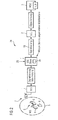
- FIG. 2 a radio access network of a radio communication system with the inventive device for deactivating a mobile station is shown simplified.
- mobile phones 6 are arranged in a radio cell 5 and are supplied by a base station 1 (BTS).
- BSC slave Between the base station 1 and the base station controller 2 is the invention Device 4 (BSC slave) arranged.
- the device 4 is connected directly downstream of the base station 1 (BTS).
- the signaling between BTS and BSC is performed according to the invention via the BSC slave unit 4.
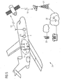
- the radio cell 5 is a pico radio cell on board an aircraft ( FIG. 5 ).
- the base station BTS and the base station controller BSC in the FIG. 5 has the well-known GSM functionality. Only the technical equipment execution of these devices 1 and 4 is adapted to the place of use in the aircraft and the information transfer between the BSC slave 4 on board the aircraft and the BSC 2 located on the ground is not by lines, but by a satellite connection 19 FIG. 5 ).
- the subassembly BSC slave 4 serves to track the communication between BTS 1 and BSC 2 and, depending on an external event, to intervene in such a way that there is no disturbing emission of radio waves and thus possibly an impairment of the avionics of the aircraft ,
- FIG. 3 starting from an operating state 8 in which a mobile station starts a search for a public land mobile network (PLMN), a signal 9 (broardcast channel, BCCH carrier in FIG FIG. 3 ) received.
- This signal 9 is continuously broadcasted by the base station BTS of a mobile communication system.
- the mobile station 6 sets a location request 10 (Location Updating Request in FIG. 3 ), which is forwarded via the base station BTS, and via the inventive device BSC slave to a digital exchange 3 (MSC) on the ground.
- This switching center 3 (MSC) responds with a signal 11, (Location Updating Accept in FIG. 3 ).
- the signal 11 includes the identifier of the mobile station 6 in the pico radio cell 5, the so-called Temporary Mobile Subscriber Identity, hereinafter abbreviated TMSI.
- TMSI Temporary Mobile Subscriber Identity
- This TMSI is now filtered out of the signal 11 by the BSC slave and stored in a memory device 20 of the BSC slave.
- This operation (Store TMSI) is in FIG. 3 marked with the reference numeral 12.
- the mobile station 6 At the end of the signal diagram in FIG. 3 is the mobile station 6 after receiving the signal 11 in an operating state 13 (On PLMN idle).
- the BSE slave 4 By recording the identifier (TMSI) in the memory device 20 of the BSC slave unit 4, the knowledge about registered mobile phones of the pico cell 5 is present not only in the digital switching center 3 (Mobile Services Switching Center) on the ground, but also in the invention Facility 4 on board the aircraft. By filtering out the TMSI, the BSE slave 4 always has knowledge of the number and the identifier of the mobile stations 6 registered in the pico-cell 5 of the aircraft.
- TMSI Mobile Services Switching Center
- the flight control If the aircraft now starts, for example, with a landing approach, then the flight control generates a deactivation signal 25 which is fed to the device (BSC slave) 4 according to the invention ( FIG. 4 and FIG. 5 ).
- the device 4 (BSC slave) knows number and identifier the registered mobile stations 6 in the pico radio cell 5 and starts to disable these terminals in succession.
- FIG. 4 the sequence of deactivation is shown in a time sequence.
- the process of deactivation is initiated with the deactivation signal 25 "Swith Off".
- the BSC slave sends a signal 14 (page TMSI In.) To each of the mobile stations 6 identified on the basis of the TMSI FIG. 4 ).
- An addressed mobile station MS responds with the signal 15 (RR Paging Response).
- the BSC slave starts exchanging security messages. For this purpose, it sends the signal 16 (MM Authentication Request) to the mobile station 6.
- the mobile station 6 in turn responds with the signal 17 (MM Authentication Response).
- the BSC slave deletes this TMSI from the memory (in FIG.
- MM Authentication Reject causes the mobile station 6 to enter an operating state 19 in which it regards its own SIM as invalid. Therefore, during the safety-critical landing approach or during a climb, the mobile station 6 no longer emits disturbing radio waves; This applies even if the aircraft has reached an altitude of less than 3,000 m and the mobile station 6 comes into the detection range of base stations of a mobile network on the ground.
- TMSI Temporary Mobile Subscriber Identity
- IMSI International Mobile Subscriber Identity
- This IMSI is communicated by the mobile device to the respective pico radio cell 5.
- certain participants can be identified and the inventive deactivation of the mobile device can be carried out for these subscribers, possibly taking into account an entry in a positive / negative list (black-white list) in a memory area of the inventive Device is stored.
- FIG. 5 the arrangement of the pico radio cell 5 is sketched in an airplane.
- the mobile stations 6 are thereby supplied via a radio interface 7 with antennas of a so-called Picocell GSM / GPRS base station guided in each case in the aircraft ceiling behind the fairing.
- private radio communication terminals such as mobile phones, wireless fidelity equipped laptops, organizers or other portable information processing terminals.
- Each of these terminals is prescribed by the base station a transmission power of a few milliwatts.
- CDMA Code Division Multiple Access
- the satellite radio link 19 can use, for example, the satellite system SATCOM or INMARSAT.
- the reference numeral 22 generally indicates the terrestrial part of the network 24. At the bottom is the base station controller 2 and the digital exchange (MSC) 3.
- the base station 1 and the device 4 according to the invention are shown in a block. This is intended to express that the device according to the invention is implemented in whole or in part as a so-called computer program product which is implemented with the base station 1, for example on a PC.
- the device 4 can be, for example, an algorithm that runs on the PC of the base station.
- the deactivation signal can be specified by a technical device or manually, for example by an operator.
Landscapes
- Engineering & Computer Science (AREA)
- Computer Networks & Wireless Communication (AREA)
- Signal Processing (AREA)
- Physics & Mathematics (AREA)
- Aviation & Aerospace Engineering (AREA)
- Astronomy & Astrophysics (AREA)
- Computer Security & Cryptography (AREA)
- General Physics & Mathematics (AREA)
- Health & Medical Sciences (AREA)
- Chemical & Material Sciences (AREA)
- Electromagnetism (AREA)
- Oil, Petroleum & Natural Gas (AREA)
- Public Health (AREA)
- Mobile Radio Communication Systems (AREA)
Description
- Die Erfindung bezieht sich auf ein Verfahren und eine Vorrichtung zum netzseitigen Deaktivieren von Mobilstationen, die in einer Funkzelle eines Funkkommunikationsnetzes eingebucht sind, insbesondere in einer Picozelle eines GSM-Mobilfunknetzes, die sich an Bord eines Flugzeugs befindet.
- Ein Mobiltelefon, das in einer Funkzelle eines Mobilfunknetzes eingebucht ist, tauscht fortlaufend Funkwellen mit einer ortsfesten Basisstation des Mobilfunknetzes aus.
- Befinden sich im Sendebereich des Mobiltelefons andere elektronische Geräte, so können die Funkwellen in diesen Geräten Störungen verursachen.
- In Krankenhäusern ist beispielsweise die Nutzung von Handys aus diesem Grund untersagt. In Flugzeugen ist die Verwendung von privaten, funkbasierten Kommunikationseinrichtungen heutzutage aus Sicherheitsgründen überhaupt nicht zugelassen. Es wird befürchtet, dass die Funkwellen der privaten mitgeführten Geräte die Avionik des Flugzeugs stören könnten.
- Andererseits nimmt die Verwendung von mobilen Kommunikationsendeinrichtungen ständig zu. Es besteht zunehmend ein Bedarf, private Kommunikationseinrichtungen, insbesondere die nach dem weit verbreiteten GSM-Standard (Global Systems for Mobile Communication), möglichst einfach und uneingeschränkt auch während einer Flugreise nutzen zu können.
- Mit der Einführung des "GSM on Board-Systems" soll zukünftig die Verwendung von privaten Mobiltelefonen in Flugzeugen unter gewissen Einschränkungen erlaubt sein. Aus Sicherheitsgründen kann hierbei nicht ausschließlich auf die Kooperationsbereitschaft der Passagiere gesetzt werden, ihre Mobiltelefone nur während der Reiseflugphase einzuschalten und während der sicherheitskritischen Start- und Landephase selbstständig abzuschalten. Um den sicherheitstechnischen Anforderungen zu genügen, scheint es zunächst möglich, die Basisstation der Funkzelle im Flugzeug bei Start bzw. Landung gesteuert durch ein von der Flugzeugelektronik bereitgestelltes Deaktivierungssignal abzuschalten. Von Nachteil wäre hierbei aber, dass für eingeschaltete Mobiltelefone Mobilfunkstationen am Boden ab einer bestimmten Flughöhe sichtbar wären und diese zur Ausstrahlung von Funkwellen animieren würden.
- Aus der
EP 0 891 110 A1 ist be4kannt, für die Deaktivierung eines an Bord eines Flugzeuges befindlichen Handsets eine Teilnehmerkenninformation IMSI zu verwenden. - In der
WO 9428684 A1 - Der Erfindung liegt die Aufgabe zu Grunde, ein Verfahren und eine Vorrichtung anzugeben, durch die Funkstörungen, die durch mobile Kommunikationsendeinrichtungen in einer Funkzelle eines Funkkommunikationsnetzes verursacht werden, auf möglichst einfache Weise netzseitig ausgeschaltet werden können.
- Die Lösung dieser Aufgabe erfolgt bei einem Verfahren durch die Merkmale des Patentanspruchs 1 und bei einer Vorrichtung durch die Merkmale des Patentanspruchs 10. Vorteilhafte Ausgestaltungen der Erfindung sind Gegenstand von jeweils abhängigen Ansprüchen.
- Erfindungsgemäß wird im Funkzugangsnetz zwischen der Basisstation (Base Transceiver Station BTS) und dem Basisstation-Controller (Base Station Controller BSC) eine Einrichtung geschaltet, welche die Anzahl und die Kennung der in der Funkzelle eingebuchten Mobilstationen registriert. Zur Kennung können zwei Teilnehmerkenninformationen, die "Temporary Mobile Subscriber Identity" (TMSI) und die "International Mobile Subscriber Identity" (IMSI) herangezogen werden. Ausgelöst von einem externen Ereignis, das als Deaktivierungssignal der Einrichtung zugeführt wird, initiiert diese Einrichtung einen Austausch von Sicherheitsnachrichten mit jeder eingebuchten Mobilstation. Im Ergebnis führt diese Interaktion dazu, dass die eingebuchten Mobilstationen ihre eigene "Subscriber Identity Module" (SIM) als ungültig, d.h. als nicht berechtigt ansehen. Infolge davon sendet keine Mobilstation mehr störende Funkwellen aus.
- Bei einer Anwendung in einem Flugzeug gilt dies auch dann, wenn bei einem Landeanflug die an Bord befindlichen Mobilstationen in den Erfassungsbereich von am Boden befindlichen Sendeeinrichtungen eines Mobilfunknetzes kommen. Der inaktive Betriebszustand der Mobilstation bleibt solange aufrechterhalten, bis der Fluggast sein Mobiltelefon manuell ab- und wieder einschaltet.
- Zur netzseitigen Deaktivierung sieht die Erfindung eine Systemkomponente vor, die im Funkzugangsnetz, direkt hinter dem ersten Netzelement, das heißt hinter der Basisstation, eingesetzt wird. Diese Systemkomponente, im Folgenden auch als BSC-Slave bezeichnet, verfolgt einerseits die Kommunikation zwischen der Basisstation BTS und den sich daran anschließenden zweiten Netzelement, dem Basisstation-Controller BSC. Andererseits ergreift diese erfindungsgemäße Einrichtung die Initiative, sobald ein externes Ereignis eintritt, das erfordert, eingebuchte Mobilstationen von Seiten des Netzes her zu deaktivieren. Die Einrichtung kann als Computerprogrammprodukt realisiert sein, Z.B. als Algorithmus, der auf einer Recheneinrichtung des ersten Netzelements abläuft.
- Indem mehrere zu einer Gruppe zusammengefasste Mobilstationen hintereinander deaktiviert werden, wird die Signalisierungskapazität in der Funkzelle nicht überschritten.
- Wenn selektiv nur bestimmte Mobilstationen in einer Funkzelle inaktiviert werden sollen, so kann dies anhand einer Positiv/Negativ-Liste erfolgen, die in der Einrichtung in einem Speicher gespeichert ist. Sobald ein Deaktivierungssignal vorliegt, wird vor dem Deaktivieren geprüft, ob die erfassten Teilnehmerkenninformationen (TMSI, IMSI) einer Mobilstation in dieser Liste enthalten sind. Dadurch können bestimmte, ausgewählte Mobilstationen in der Funkzelle tätig beleiben, andere werden gesperrt. Eine denkbare Anwendung könnte ein Gelände einer Schule sein, innerhalb dessen eine Gruppe von Kommunikationsteilnehmern (z.B. dem Lehrkörper) ihre Handys benutzen dürfen, einer anderen Gruppe (z.B. Schülern) hingen die Nutzung zumindest temporär (z.B. zu Unterrichtszeiten) nicht erlaubt ist.
- Das Erfassen der ersten Teilnehmerkenninformation kann so erfolgen, dass eine über die Einrichtung geführte Aufenthalts-Registrierungs-Nachricht verwendet wird, welche als Antwort auf eine Anfrage einer Mobilstation vom dritten Netzelement an die anfordernde Mobilstation übertragen wird.
- Beim Erfassen der zweiten Teilnehmerkenninformation kann mit Vorteil eine über die Einrichtung geführte Aufenthalts-Registrierungs-Nachricht verwendet werden, welche als Anfrage einer Mobilstation an das dritte Netzelement übertragen wird.
- Es ist von Vorteil, wenn die Einrichtung dem zweiten Netzelement hierarchisch untergeordnete ist. Dadurch kann der Funktionsumfang, der als "Slave" betriebenen Einrichtung klein gehalten werden.
- Dies ist insbesondere dann günstig, wenn die Einrichtung und das erste Netzelement an Bord eines Luftfahrzeuges eingesetzt werden, wo Ressourcen nur eingeschränkt verfügbar sind und strenge Anforderungen hinsichtlich der Ausfallsicherheit vorgegeben sind.
- Bei einer Anwendung in einem Flugzeug ist ferner von Vorteil, wenn das zweite Netzelement als "Master" betreiben wird und zusammen mit dem dritte Netzelement am Boden angeordnet sind. Für die Signalübermittlung zwischen der Einrichtung und dem zweiten Netzelement kann vorteilhaft eine Satellitenübertragung genutzt werden.
- Die Realisierung der Einrichtung kann beispielsweise ganz oder teilweise durch Computerprogrammprodukt erfolgen, z.B. durch ein Computerprogramm auf einem entsprechend konfigureirten Server.
- Zur weiteren Erläuterung der Erfindung wird im nachfolgenden Teil der Beschreibung auf die Zeichnungen Bezug genommen, aus denen weitere vorteilhafte Ausgestaltungen, Einzelheiten und Weiterbildungen der Erfindung zu entnehmen sind. Es zeigen:
- Figur 1
- ein Funkzugangsnetz eines GSM-Mobilfunknetzes gemäß dem Stand der Technik in einer vereinfachten Darstellung;
- Figur 2
- ein Funkzugangsnetz eines Funkkommunikationssystem mit der erfindungsgemäßen Einrichtung zum Deaktivieren einer mobilen Station in einer schematischen Darstellung;
- Figur 3
- einen Protokollablauf bei der erfindungsgemäßen Aufzeichnung der Kennung einer Mobilstation durch die erfindungsgemäße Einrichtung zum Deaktivieren;
- Figur 4
- einen Protokollablauf beim netzseitigen Abschalten einer mobilen Station durch die erfindungsgemäße Einrichtung;
- Figur 5
- ein Ausführungsbeispiel der Erfindung, bei dem sich Mobilstationen in einer Picozelle an Bord eines Flugzeugs befinden.
- Im Folgenden Teil der Beschreibung wird die Erfindung am Beispiel eines GSM-On-Board-Funkkommunikationssystems eines Flugzeugs beschrieben. Selbstverständlich ist die Erfindung nicht auf diese Anwendung oder auf eine bestimmte Ausführung eines Funkkommunikationssystems beschränkt. Unter einem Funkkommunikationssystem ist allgemein ein System zu verstehen, in welchem eine Informationsübermittlung durch Funkwellen stattfindet. Das Funkkommunikationssystem gemäß der Erfindung kann also ein beliebiges Mobilfunksystem sein, beispielsweise nach dem bereits erwähnten GSM Standard (Global System for Mobile Communications), ein diensteintegrierendes Netz, zum Beispiel gemäß dem UMTS-(Universal Mobile Telecommunications System) Standard, oder ein System der vierten Generation sein. Hervorgehoben sei auch, dass unter einem Funkkommunikationssystem auch leitungsungebundene lokale Netze, wie beispielsweise WLAN (Wire Less Lan gemäß dem Standard IEEE 802.11 sowie Breitbandnetze mit drahtlosem Zugang, beispielsweise nach dem Standard IEEE 802.16 und ähnliche Netze verstanden sind.
- In der
Figur 1 ist der Funkzugangsbereich eines herkömmlichen GSM-Mobilfunknetzes schematisch dargestellt, wobei die Funktion der einzelnen Baugruppen als bekannt vorausgesetzt werden und hier nur insoweit angesprochen werden, wie dies für die Erläuterung der vorliegenden Erfindung dienlich ist. - Ein GSM-Netz besteht bekanntlich aus zwei Arten von Teilstrecken. Zum einen sind es die Funkstrecken zwischen den mobilen Stationen (MS) und jeweils einer Basisstation (BTS), die einen festgelegten Versorgungsbereich abdeckt. Zum anderen sind es Standleitungen des Festnetzes, welche die Basisstationen mit Vermittlungseinrichtungen (Mobile Switching Center), sowie die Vermittlungseinrichtungen untereinander verbinden. In der
Figur 1 ist eine Gruppe von Mobilstationen 6 (MS) zu sehen, die über eine Funkübertragungsstrecke 7 von einem ersten Netzelement 1, (Basisstation BTS), versorgt werden. Dieser Basisstation 1 ist ein zweites Netzelement 2, ein so genannter Basisstation-Controller BSC, nachgeschaltet. Der Basisstation-Controller BSC 2 steuert über eine Signalisierungsverbindung (Abis Link) eine oder mehrere Basisstationen BTS. Der BSC ist andererseits durch eine Verbindung A-link mit einem dritten Netzelement, (Mobil Switching Center MSC), verbunden. Das Mobile Switching Center stellt wie bereits erwähnt in einem digitalen GSM/UMTS-Mobilfunknetz eine volle digitale Vermittlungsstelle dar. In ihr findet die Anrufverwaltung statt. Sie besitzt u. A. eine spezielle Datei, ein Besucherverzeichnis, das so genannten Visitor Location Register, kurz VLR. Sie enthält die Daten derjenigen Mobilstationen, die sich vorübergehend im Bereich der MSC aufhalten. In dieser Datei ist also das Wissen über die angemeldeten Mobilstationen gespeichert. - In der
Figur 2 ist ein Funkzugangsnetz eines Funkkommunikationssystems mit der erfindungsgemäßen Einrichtung zum Deaktivieren einer mobilen Station vereinfacht dargestellt. Auch hier sind Mobiltelefone 6 in einer Funkzelle 5 angeordnet und werden von einer Basisstation 1 (BTS) versorgt. Zwischen der Basisstation 1 und dem Basisstation-Controller 2 ist die erfindungsgemäße Einrichtung 4 (BSC-Slave) angeordnet. Die Einrichtung 4 ist unmittelbar der Basisstation 1 (BTS) nachgeschaltet. Die Signalisierung zwischen BTS und BSC wird erfindungsgemäß über die BSC-Slave-Einheit 4 geführt. - Im Weiteren wird ein Ausführungsbeispiel der Erfindung beschrieben, bei dem die Funkzelle 5 eine Pico-Funkzelle an Bord eines Flugzeugs ist (
Figur 5 ). Die Basisstation BTS und der Basisstation-Controller BSC in derFigur 5 weist die bekannte GSM-Funktionalität auf. Lediglich die gerätetechnische Ausführung dieser Geräte 1 und 4 ist an den Einsatzort im Flugzeug angepasst und die Informationsübertragung zwischen dem BSC-Slave 4 an Bord des Flugzeugs und der am Boden befindlichen BSC 2 erfolgt nicht durch Leitungen, sondern durch eine Satellitenverbindung 19 (Figur 5 ). - Die erfindungsgemäße Baugruppe BSC-Slave 4 dient dazu, die Kommunikation zwischen BTS 1 und BSC 2 zu verfolgen und in Abhängigkeit eines externen Ereignisses steuernd so einzugreifen, dass es nicht zu einem störenden Aussenden von Funkwellen und damit womöglich zu einer Beeinträchtigung der Avionik des Flugzeugs kommt.
- Im Folgenden wird der Protokollablauf beim Deaktivieren eingebuchter Mobilstationen 6 durch Signaldiagramme näher erläutert; in den
Figuren 3 und4 ist die Zeit mit einem Pfeil und mit dem Buchstaben "t" gekennzeichnet. - Wie aus
Figur 3 zu entnehmen ist, wird ausgehend von einem Betriebszustand 8, in welchem eine Mobilstation einen Suchvorgang nach einem Public Land Mobile Network (PLMN) startet, von der Mobilstation 6 ein Signal 9 (Broardcast-Channel, BCCH-Carrier inFigur 3 ) empfangen. Dieses Signal 9 wird von der Basisstation BTS eines Mobilfunksystems fortwährend ausgestrahlt. Die Mobilstation 6 setzt daraufhin eine Aufenthaltsanfrage 10 (Location Updating Request inFigur 3 ) ab, welche über die Basisstation BTS, sowie über die erfindungsgemäße Einrichtung BSC-Slave zu einer digitalen Vermittlungsstelle 3 (MSC) am Boden weitergeleitet wird. Diese Vermittlungsstelle 3 (MSC) antwortet mit einem Signal 11, (Location Updating Accept inFigur 3 ). Das Signal 11 beinhaltet die Kennung der Mobilstation 6 in der Pico-Funkzelle 5, die sog. Temporary Mobile Subscriber Identity, im Folgenden abgekürzt TMSI. Diese TMSI wird nun vom BSC-Slave aus dem Signal 11 heraus gefiltert, und in einer Speichereinrichtung 20 des BSC-Slave gespeichert. Dieser Vorgang (Store TMSI) ist inFigur 3 mit dem Bezugszeichen 12 gekennzeichnet. Am Ende des Signaldiagramms inFigur 3 befindet sich die Mobilstation 6 nach Empfang des Signals 11 in einem Betriebszustand 13 (On PLMN idle). - Durch die Aufzeichnung der Kennung (TMSI) in der Speichereinrichtung 20 der BSC-Slave-Einheit 4 liegt das Wissen über angemeldete Mobiltelefone der Picozelle 5 nicht nur in der digitalen Vermittlungsstelle 3 (Mobile Services Switching Center) am Boden vor, sondern auch in der erfindungsgemäßen Einrichtung 4 an Bord des Flugzeugs. Durch das Herausfiltern der TMSI hat der BSE-Slave 4 stets Kenntnis über die Anzahl und die Kennung der in der Picozelle 5 des Flugzeugs eingebuchten Mobilstationen 6.
- Beginnt nun das Flugzeug beispielsweise mit einem Landeanflug, so erzeugt die Flugsteuerung eine Deaktivierungssignal 25, das der erfindungsgemäßen Einrichtung (BSC-Slave) 4 zugeführt wird (
Figur 4 undFigur 5 ). Die Einrichtung 4 (BSC-Slave) kennt Anzahl und Kennung der eingebuchten Mobilstationen 6 in der Pico-Funkzelle 5 und beginnt diese Endgeräte nacheinander zu deaktivieren. - In
Figur 4 ist der Ablauf des Deaktivierens in einem zeitlichen Ablauf dargestellt. Der Vorgang des Deaktivierens wird mit dem Deaktivierungssignal 25 "Swith Off" eingeleitet. Der BSC-Slave sendet darauf hin nacheinander an jedes der an Hand der TMSI identifizierten Mobilstationen 6 ein Signal 14 (Page TMSI InFigur 4 ). Eine angesprochenen Mobilstation MS antwortet mit dem Signal 15 (RR Paging Response). Nun beginnt der BSC-Slave mit einem Austausch von Sicherheitsnachrichten. Hierzu sendet er das Signal 16 (MM Authentication Request) an die Mobilstation 6. Die Mobilstation 6 antwortet wiederum mit dem Signal 17 (MM Authentication Response). Obwohl die angesprochene Mobilstation 6 an sich berechtigt wäre, löscht der BSC-Slave diese TMSI aus dem Speicher (inFigur 4 Delete TMSI from list)und übermittelt an die Mobilstation 6 ein Ablehnungssignal 18 (MM Authentication Reject), das gemäß GSM-Norm 04.08 bewirkt, dass die Mobilstation 6 in einen Betriebszustand 19 übergeht, in welchem sie ihre eigene SIM als ungültig ansieht. Daher sendet die Mobilstation 6 während des sicherheitskritischen Landeanflugs bzw. während eines Steigflugs keine störenden Funkwellen mehr aus; dies gilt selbst dann, wenn das Flugzeug eine Flughöhe von kleiner als 3.000 m erreicht hat und die Mobilstation 6 in den Erfassungsbereich von Basisstationen eines Mobilfunknetzes am Boden kommt. - Die Temporary Mobile Subscriber Identity (TMSI) ist eine lokal und zeitlich begrenzte Identifikation der Mobilstation innerhalb der Pico-Funkzelle des Flugzeugs. Die TMSI erhält der Fluggast beim Betreten der Pico-Funkzelle 5. Verlässt der Fluggast das Flugzeug und schaltet er seine Mobilstation aus- und wieder ein, so findet ein Handover statt und die TMSI wird vom Netzelement 3 neu vergeben.
- Eine permanente Identifikation eines Teilnehmers eines Mobilfunksystems ist durch die International Mobile Subscriber Identity (IMSI) gegeben. Diese IMSI wird vom Mobilfunkgerät der jeweiligen Pico-Funkzelle 5 mitgeteilt. Auf Basis der IMSI lassen sich bestimmte Teilenehmer erkennen und es lässt sich für diese Teilnehmer die erfindungsgemäße Deaktivierung des Mobilfunkgerätes durchführen, ggf. unter Berücksichtigung eines Eintrags in einer Positiv/Negativ-Liste (Black-White-List), die in einem Speicherbereich der erfindungsgemäßen Einrichtung abgelegt ist.
- In
Figur 5 ist die Anordnung der Pico-Funkzelle 5 in einem Flugzeug skizziert. Die Mobilstationen 6 werden dabei über eine Funkschnittstelle 7 mit jeweils in der Flugzeugdecke hinter der Verkleidung geführten Antennen einer so genannten Picocell-GSM/GPRS-Basisstation versorgt. Dadurch ist an jedem Sitzplatz des Flugzeugs der Empfang für private Funk-Kommunikations-Endgeräte, wie Handy, WiFi (wireless fidelity) equipped Laptops, Organizer oder andere tragbare, informationsverarbeitende Endgeräte möglich. Jede dieser Endgeräte wird durch die Basisstation eine Sendeleistung von wenigen Milliwatt vorgeschrieben. Gemäß der Erfindung ist sichergestellt, dass die privaten Endgeräte der Avionik des Flugzeugs nicht stören. Für den Fall, dass sich unter den Fluggästen ein aktiviertes Mobiltelefon eines anderen Standards (zum Beispiel CDMA) befindet, werden diese Funksignale von einer hier nicht näher dargestellten Vorrichtung erfasst und der Fluggast zum Ausschalten des Terminals aufgefordert. - Auf diese Weise wird erreicht, dass der Funkverkehr vom Flugzeug aus ausschließlich über die Satellitenfunkstrecke 19 abgewickelt wird. Die Satellitenfunkstrecke 19 kann beispielsweise das Satellitensystem SATCOM oder INMARSAT nutzen. In
Figur 5 ist mit dem Bezugszeichen 22 allgemein der terrestrische Teil des Netzes 24 bezeichnet. Am Boden befindet sich die Basisstation-Controller 2 und die digitale Vermittlungsstelle (MSC) 3. - Im Ausführungsbeispiel der
Figur 5 ist die Basisstation 1 und die erfindungsgemäßen Einrichtung 4 in einem Block dargestellt. Damit soll zum Ausdruck gebracht werden, dass die erfindungsgemäße Einrichtung ganz oder teilweise als sog. Computerprogrammprodukt realisiert ist, das mit der Basisstation 1 beispielsweise auf einem PC implementiert ist. Die Einrichtung 4 kann beispielsweise ein Algorithmus sein, der auf dem PC der Basisstation abläuft. - Selbstverständlich ist die Erfindung weder auf ein bestimmtes Kommunikationsnetz noch auf den vorliegenden Anwendungsfall beschränkt.
- Es ist denkbar, dass ähnliche Anforderungen der Aktivierung von Mobilfunkgeräten beispielsweise in Krankenhäusern, in Laboratorien oder in anderen Einrichtungen in denen erhöhte Anforderungen hinsichtlich der elektromagnetischen Verträglichkeit vorlegen. Je nach Anwendung kann das Deaktivierungssignal durch eine technische Einrichtung oder manuell, beispielsweise von einem Operator vorgegeben werden.
-
- 1 erstes Netzelement, Basisstation
- 2 zweites Netzelement, Basisstation-Controller
- 3 drittes Netzelement, digitale Vermittlungsstelle
- 4 Einrichtung, BSC-Slave
- 5 Mobilfunkzelle, Picozelle
- 6 Mobilstation, funkbasierte Teilnehmerendeinrichtung
- 7 Funkübertragungsstrecke zwischen 6 und 1
- 8 Ausgangszustand bei Aufenthaltsregistrierung
- 9 BCCH-Signal
- 10 Location Updating Request-Signal
- 11 Location Updating Accept-Signal
- 12 Speichern der TMSI
- 13 Zustand von 6 nach dem Speichern der TMSI
- 14 Page-TMSI-Signal
- 15 Paging Response
- 16 Authentication Request
- 17 Authentication Response
- 18 Authentication Reject
- 19 Zustand von 6 "SIM ungültig"
- 20 Speichereinrichtung in 4
- 21 Bodenstation
- 22 terrestrischen Teil des Netzes
- 23 Kommunikationsteilnehmer am Boden
- 24 Funkkommunikationssystem
- 25 Deaktivierungssignal
Claims (19)
- Verfahren zum Deaktivieren von Mobilstationen in einer Funkzelle eines Funkkommunikationssystems, insbesondere in einer an Bord eines Flugzeugs befindlichen Picozelle eines GSM-Mobilfunknetzes, wobei das
Funkkommunikationssystem- ein erstes Netzelement (1), das eine Sende-Empfangseinrichtung für jede Mobilstation (6) der Funkzelle (5) bildet,- ein zweites Netzelement (2), das zum Steuern des ersten Netzelementes eingerichtet ist, und- eine Einrichtung (4), die zwischen dem ersten Netzelement (1) und dem zweiten Netzelement (2) geschaltet ist, umfasst,und wobei die Einrichtung (4) folgende Schritte durchführt:- Erfassen einer ersten und einer zweiten Teilnehmerkenninformation (TMSI, IMSI), welche bei einem Austausch von Signalisierungsinformationen zwischen einer dieser Mobilstationen (6) und einem dritten Netzelement (3) übermittelt werden, wobei der Übermittlungsweg über die Einrichtung (4) geführt ist,- Speichern der erfassten Teilnehmerkenninformationen (TMSI, IMSI) in einer Speichereinrichtung (20) der Einrichtung (4),- Verwenden der gespeicherten Teilnehmerkenninformationen (TMSI, IMSI) beim Deaktivieren, wobei mehrere Mobilstationen (6) jeweils in Gruppen zusammengefasst und sequenziell hintereinander deaktiviert werden, wenn ein Deaktivierungssignal (25) der Einrichtung (4) zugeführt wird. - Verfahren nach Anspruch 1, dadurch gekennzeichnet, dass der Austausch der Signalisierungsinformationen von der Einrichtung (4) initiiert wird.
- Verfahren nach Anspruch 1 oder 2, dadurch gekennzeichnet, dass das Deaktivieren einer Mobilstation (6) davon abhängig gemacht wird, ob die erfasste Teilnehmerkenninformationen (TMSI, IMSI) in einer Liste enthalten sind, die in der Einrichtung (4) vorhanden ist.
- Verfahren nach Anspruch 1, 2 oder 3, dadurch gekennzeichnet, dass beim Erfassen der ersten Teilnehmerkenninformation (TMSI) eine über die Einrichtung (4) geführte Aufenthalts-Registrierungs-Nachricht (11) verwendet wird, welche als Antwort auf eine Anfrage einer Mobilstation (6) vom dritten Netzelement (3) an die anfordernde Mobilstation (6) übertragen wird.
- Verfahren nach Anspruch 1, 2 oder 3, dadurch gekennzeichnet, dass beim Erfassen der zweiten Teilnehmerkenninformation (IMSI) eine über die Einrichtung (4) geführte Aufenthalts-Registrierungs-Nachricht (11) verwendet wird, welche als Anfrage einer Mobilstation (6) an das dritte Netzelement (3) übertragen wird.
- Verfahren nach einem der Ansprüche 1 bis 5, dadurch gekennzeichnet, dass die Einrichtung (4) dem zweiten Netzelement (2) hierarchisch untergeordnet wird.
- Verfahren nach einem der Ansprüche 1 bis 6, dadurch gekennzeichnet, dass die Einrichtung (4) und das erste Netzelement (1) an Bord eines Flugzeugs angeordnet werden.
- Verfahren nach einem der Ansprüche 1 bis 7, dadurch gekennzeichnet, dass die Einrichtung (4) als Computerprogrammprodukt ausgeführt wird.
- Verfahren nach Anspruch 7 oder 8, dadurch gekennzeichnet, dass das zweite Netzelement (2) und das dritte Netzelement (3) außerhalb des Flugzeugs angeordnet werden und dass für die Signalübermittlung zwischen der Einrichtung (4) und dem zweiten Netzelement (2) eine über Satelliten geführte Verbindung (19) verwendet wird.
- Vorrichtung zum Deaktivieren von Mobilstationen in einer Funkzelle eines Funkkommunikationssystems, insbesondere in einer an Bord eines Flugzeugs befindlichen Picozelle eines GSM-Mobilfunknetzes, umfassend:- ein erstes Netzelement (1), das eine Sende-Empfangseinrichtung für jede Mobilstation (6) darstellt,- ein zweites Netzelement (2), das zum Steuern des ersten Netzelementes (1) ausgebildet ist,- eine Einrichtung (4), welche in einen Signalisierungspfad zwischen dem ersten Netzelement (1) und dem zweiten Netzelement (2) geschalten ist,- wobei die Einrichtung (4) derartig ausgebildet ist, sodass sie eine erste und eine zweite Teilnehmerkenninformation (TMSI, IMSI) erfasst, die zwischen der zumindest einen Mobilstation (6) und einem dritten Netzelement (3) übermittelt werden, diese in einer Speichereinrichtung (20) speichert und zum Deaktivieren der zumindest einen Mobilstation (6) verwendet, wobei die Einrichtung (4) außerdem so ausgebilded ist, dass sie mehrere Mobilstationen (6) in Gruppen zusammenfasst und Mobilstationen einer Gruppe sequenziell nacheinander deaktiviert, wenn der Einrichtung (4) ein Deaktivierungssignal (25) zugeführt ist.
- Vorrichtung nach Anspruch 10, dadurch gekennzeichnet, dass die Einrichtung (4) einen Austausch von Signalisierungsinformationen mit jeder in der Funkzelle befindlichen Mobilstation initiiert.
- Vorrichtung nach Anspruch 11, dadurch gekennzeichnet, dass die Einrichtung (4) das Deaktivieren einer Mobilstation (6) davon abhängig macht, ob die erfassten Teilnehmerkenninformationen (TMSI, IMSI) in einer Liste enthalten sind, die in der Einrichtung (4) vorhanden ist.
- Vorrichtung nach Anspruch 12, dadurch gekennzeichnet, dass die erste Teilnehmerkenninformation (TMSI) in einer über die Einrichtung (4) geführten Aufenthalts-Registrierungs-Nachricht (11) enthalten ist, welche als Antwort auf eine Anfrage einer Mobilstation (6) von dem dritten Netzelement (3) an die anfordernde Mobilstation (6) übertragen wird.
- Vorrichtung nach Anspruch 12, dadurch gekennzeichnet, dass die zweiten Teilnehmerkenninformation (IMSI) in einer über die Einrichtung (4) geführten Aufenthalts-Registrierungs-Nachricht (11) enthalten ist, welche als Anfrage einer Mobilstation (6) an das dritte Netzelement (3) übertragen wird.
- Vorrichtung nach einem der Ansprüche 10 bis 14, dadurch gekennzeichnet, dass die Einrichtung (4) dem zweiten Netzelement (2) hierarchisch untergeordnet ist.
- Vorrichtung nach einem der Ansprüche 10 bis 15, dadurch gekennzeichnet, dass die Einrichtung (4) und das erste Netzelement (1) an Bord eines Flugzeugs angeordnet sind.
- Vorrichtung nach einem der Ansprüche 10 bis 16, dadurch gekennzeichnet, dass die Einrichtung (4) als Computerprogrammprodukt realisiert ist.
- Vorrichtung nach Anspruch 17, dadurch gekennzeichnet, dass das zweite Netzelement (2) außerhalb des Flugzeugs angeordnet sind.
- Vorrichtung nach Anspruch 18, dadurch gekennzeichnet, dass das zweite Netzelement (2) am Boden angeordnet ist und dass die Signalübermittlung zwischen der Einrichtung (4) und dem zweiten Netzelement (2) eine über Satelliten geführte Verbindung (19) ist.
Applications Claiming Priority (2)
| Application Number | Priority Date | Filing Date | Title |
|---|---|---|---|
| DE102005060029A DE102005060029A1 (de) | 2005-12-15 | 2005-12-15 | Verfahren und Vorrichtung zum netzseitigen Deaktivieren von Mobilfunkstationen |
| PCT/EP2006/066092 WO2007071462A1 (de) | 2005-12-15 | 2006-09-07 | Verfahren und vorrichtung zum netzseitigen deaktivieren von mobilfunkstationen |
Publications (2)
| Publication Number | Publication Date |
|---|---|
| EP1961255A1 EP1961255A1 (de) | 2008-08-27 |
| EP1961255B1 true EP1961255B1 (de) | 2010-11-03 |
Family
ID=37434225
Family Applications (1)
| Application Number | Title | Priority Date | Filing Date |
|---|---|---|---|
| EP06793292A Active EP1961255B1 (de) | 2005-12-15 | 2006-09-07 | Verfahren und vorrichtung zum deaktivieren von mobilfunkstationen |
Country Status (5)
| Country | Link |
|---|---|
| US (1) | US8195199B2 (de) |
| EP (1) | EP1961255B1 (de) |
| AT (1) | ATE487347T1 (de) |
| DE (2) | DE102005060029A1 (de) |
| WO (1) | WO2007071462A1 (de) |
Families Citing this family (8)
| Publication number | Priority date | Publication date | Assignee | Title |
|---|---|---|---|---|
| EP2062365B1 (de) * | 2006-09-15 | 2017-06-07 | Thales Avionics, Inc. | System und verfahren zur drahtlosen übertragung von inhalten in ein und aus einem flugzeug |
| US20090070841A1 (en) * | 2007-09-12 | 2009-03-12 | Proximetry, Inc. | Systems and methods for delivery of wireless data and multimedia content to aircraft |
| GB2458103B (en) * | 2008-03-03 | 2011-01-19 | I P Access Ltd | Method and apparatus for restricting access to a cellular communication network |
| AT510447B1 (de) * | 2010-09-20 | 2012-04-15 | Siemens Programm-Und Systementwicklung Gmbh & Co K | Verfahren zum deaktivieren von mobilstationen |
| DE102010062339A1 (de) * | 2010-12-02 | 2012-06-06 | Siemens Programm- Und Systementwicklung Gmbh & Co. Kg | Verfahren zum Erkennen von aktiven Mobilstationen |
| DE102011079972B4 (de) * | 2011-07-28 | 2017-07-06 | Siemens Convergence Creators Gmbh | Verfahren zum Übertragen von Informationsdaten |
| EP3725013B1 (de) | 2017-12-13 | 2023-02-01 | Telefonaktiebolaget LM Ericsson (publ) | Verfahren, basisstation und drahtlose vorrichtung zur handhabung von verbindungen von drahtlosen vorrichtungen mit luftgestützten basisstationen |
| US12457541B2 (en) * | 2022-07-27 | 2025-10-28 | At&T Intellectual Property I, L.P. | Limiting the use of signals with a potentially interfering band by user equipment operated above ground level |
Family Cites Families (22)
| Publication number | Priority date | Publication date | Assignee | Title |
|---|---|---|---|---|
| SE500443C2 (sv) | 1993-05-26 | 1994-06-27 | Nordictel Ab | Mobilkommunikationssystem |
| FI101584B1 (fi) * | 1995-11-24 | 1998-07-15 | Nokia Telecommunications Oy | Matkaviestintilaajan tunnusluvun tarkistaminen |
| EP0956720A2 (de) * | 1997-01-31 | 1999-11-17 | MAZ Mikroelektronik Anwendungszentrum Hamburg GmbH | Verfahren zum detektieren von mobilfunkstationen |
| EP0891110A1 (de) * | 1997-07-10 | 1999-01-13 | Alcatel | Verfahren und System zum Verhindern von Störungen durch eine Mobilstation |
| KR20010023816A (ko) * | 1997-09-09 | 2001-03-26 | 칼 하인쯔 호르닝어 | 이동 무선전화 단말기들, 무선국 및 이동 무선전화단말기에 의해 방출되는 전자기 방사선으로부터 제한된국부 영역을 보호하는 방법 |
| US6014568A (en) * | 1997-09-30 | 2000-01-11 | Ericsson Inc. | Location-based voice coder selection |
| US6125283A (en) * | 1998-05-18 | 2000-09-26 | Ericsson Inc. | Multi-mode mobile terminal and methods for operating the same |
| DE19833777A1 (de) * | 1998-07-27 | 2000-02-03 | Siemens Ag | Verfahren, Vorrichtung und System zum Betreiben von mobilen Telekommunikationsendgeräten in einem öffentlichen, zellularen Mobilfunknetz |
| KR100300350B1 (ko) * | 1998-10-20 | 2001-09-06 | 윤종용 | 휴지상태의이동전화기감지장치및방법 |
| US6799155B1 (en) * | 1998-12-11 | 2004-09-28 | Allied Signal Inc. | Replacement of externally mounted user interface modules with software emulation of user interface module functions in embedded processor applications |
| EP1041847A1 (de) * | 1999-03-12 | 2000-10-04 | Sony International (Europe) GmbH | Schützen eines vorbestimmten Bereiches vor störender Benutzung von mobilen Endgeräten mittels einer Standortaktualisierungsantwortnachricht |
| FR2791510B1 (fr) * | 1999-03-22 | 2001-05-04 | Cit Alcatel | Procede de protection radioelectrique |
| GB2350972A (en) * | 1999-06-08 | 2000-12-13 | Marconi Electronic Syst Ltd | Aircraft communication arrangement |
| US6799052B2 (en) * | 2001-02-08 | 2004-09-28 | Michael K. Agness | Hand-held cellular telephone system with location transmission inhibit |
| US20070129012A1 (en) * | 2003-04-01 | 2007-06-07 | Iceberg Systems Limited | Portable digital devices |
| KR100511317B1 (ko) * | 2003-10-31 | 2005-08-31 | 엘지전자 주식회사 | 비접촉식 카드를 내장한 이동 통신 단말기의 카드 도용방지 방법 및 장치 |
| US7613480B2 (en) * | 2003-12-31 | 2009-11-03 | At&T Mobility Ii Llc | Multiple subscription subscriber identity module (SIM) card |
| US7933608B2 (en) * | 2004-03-11 | 2011-04-26 | Tekelec | Methods, systems, and computer program products for providing presence gateway functionality in a telecommunications network |
| NO20041347L (no) * | 2004-03-31 | 2005-10-03 | Telenor Asa | Subscriber identity module |
| WO2005122618A1 (en) * | 2004-06-08 | 2005-12-22 | Telefonaktiebolaget L M Ericsson (Publ) | Method and radio communication network for detecting the presence of fraudulent subscriber identity modules |
| GB0500911D0 (en) * | 2005-01-17 | 2005-02-23 | Vodafone Ltd | Controlling use of mobile devices |
| US20070129057A1 (en) * | 2005-12-06 | 2007-06-07 | Chuan Xu | Service provider subsidy lock |
-
2005
- 2005-12-15 DE DE102005060029A patent/DE102005060029A1/de not_active Ceased
-
2006
- 2006-09-07 WO PCT/EP2006/066092 patent/WO2007071462A1/de not_active Ceased
- 2006-09-07 US US12/086,446 patent/US8195199B2/en active Active
- 2006-09-07 EP EP06793292A patent/EP1961255B1/de active Active
- 2006-09-07 AT AT06793292T patent/ATE487347T1/de active
- 2006-09-07 DE DE502006008254T patent/DE502006008254D1/de active Active
Also Published As
| Publication number | Publication date |
|---|---|
| US8195199B2 (en) | 2012-06-05 |
| EP1961255A1 (de) | 2008-08-27 |
| ATE487347T1 (de) | 2010-11-15 |
| DE502006008254D1 (de) | 2010-12-16 |
| WO2007071462A1 (de) | 2007-06-28 |
| DE102005060029A1 (de) | 2007-06-21 |
| US20090047941A1 (en) | 2009-02-19 |
Similar Documents
| Publication | Publication Date | Title |
|---|---|---|
| DE60008786T2 (de) | Anrufumleitungssystem | |
| DE69218715T2 (de) | Verfahren zur Umschaltung des nach Endgeräten gerichteten Verkehrs in einer Satellitenübertragungsanordnung mit Umlaufbahnen niedriger Höhe und Kommunikationssystem für dieses Verfahren | |
| EP2145489B1 (de) | Verfahren zum bereitstellen von ortsbezogenen diensten zu teilnehmerendgeräten eines funkkommunikationssystems | |
| DE60036147T2 (de) | Knoten und Station an Bord eines Fahrzeuges zur Verbindungsaufnahme mit einem Fahrzeuginsassen | |
| DE102008062546B4 (de) | Verfahren zum Steuern des Timing von drahtlosen Übermittlungen zwischen Fahrzeugen mit Telematikausstattung und einem Call Center | |
| DE112018004690T5 (de) | Drahtlose kommunikationsvorrichtung | |
| DE19831086A1 (de) | Telekommunikationssystem | |
| EP1961255B1 (de) | Verfahren und vorrichtung zum deaktivieren von mobilfunkstationen | |
| EP1121816A2 (de) | Übergabeverfahren (roaming) für mobile endeinrichtungen | |
| EP0849891A2 (de) | Verfahren und Anordnung zum Aufbau einer Nutzkanalverbindung in einem Mobilfunknetz | |
| DE102018117497B4 (de) | Drahtlose fahrzeugeinheit und verfahren zu deren betrieb | |
| DE102013003063B4 (de) | Steuerung des Kommunikationsverhaltens eines Kraftfahrzeugs | |
| DE602004008435T2 (de) | Mobile Kommunikationsanordnung für Schiffe mit einer Satellitenverbindung | |
| DE102007024370B4 (de) | Picozelle in einem Flugzeug und Steuerungsverfahren für drahtlose Datenübertragung | |
| DE102016204996B3 (de) | Vorrichtung, Verfahren und Computerprogramm zur Gruppenbildung von Geräten durch Ortung | |
| EP0856999B1 (de) | Vorrichtung zum Verhindern von Sendeaktivitäten einer Mobilfunkstation | |
| AT510447B1 (de) | Verfahren zum deaktivieren von mobilstationen | |
| WO2005011318A1 (de) | Verfahren zur steuerung des einbuchens einer mobilen station eines funkkommunikationssystems in eine funkzelle einer virtuellen basisstation sowie virtuelle basisstation | |
| DE102008047543A1 (de) | Minimierung des Signalisierungsverkehrs bei Home Base Stations | |
| EP2814275A1 (de) | Telekommunikationsanordnung und Verfahren für die Mobilkommunikation | |
| DE102005027027B4 (de) | Verfahren zur Authentisierung eines mobilen Testgerätes in einem Mobilfunknetz sowie Testsystem zur Überprüfung von Übertragungsvorgängen innerhalb eines Mobilfunknetzes und zur Durchführung eines derartigen Authentisierungsverfahrens | |
| DE102019109100A1 (de) | Drahtloskommunikationsvorrichtung für eine Mehrzahl von Drahtloskommunikationsteilnehmern in einem Fortbewegungsmittel | |
| DE112015006482T5 (de) | Automatisches zusammenführen und trennen mehrerer digitaler fahrzeugrepeater | |
| DE19708793C1 (de) | Verfahren und Anordnung zum gesteuerten Erzeugen einer Verkehrslast in Mobilfunksystemen | |
| DE102016117409B4 (de) | Konfigurierbares kommunikationsmodul mit austauschbarer netzzugriffseinrichtung |
Legal Events
| Date | Code | Title | Description |
|---|---|---|---|
| PUAI | Public reference made under article 153(3) epc to a published international application that has entered the european phase |
Free format text: ORIGINAL CODE: 0009012 |
|
| 17P | Request for examination filed |
Effective date: 20080424 |
|
| AK | Designated contracting states |
Kind code of ref document: A1 Designated state(s): AT BE BG CH CY CZ DE DK EE ES FI FR GB GR HU IE IS IT LI LT LU LV MC NL PL PT RO SE SI SK TR |
|
| 17Q | First examination report despatched |
Effective date: 20090507 |
|
| GRAP | Despatch of communication of intention to grant a patent |
Free format text: ORIGINAL CODE: EPIDOSNIGR1 |
|
| RIC1 | Information provided on ipc code assigned before grant |
Ipc: H04W 48/02 20090101AFI20100303BHEP |
|
| RTI1 | Title (correction) |
Free format text: METHOD AND APPARATUS FOR DEACTIVATING MOBILE RADIO STATIONS |
|
| GRAS | Grant fee paid |
Free format text: ORIGINAL CODE: EPIDOSNIGR3 |
|
| GRAA | (expected) grant |
Free format text: ORIGINAL CODE: 0009210 |
|
| AK | Designated contracting states |
Kind code of ref document: B1 Designated state(s): AT BE BG CH CY CZ DE DK EE ES FI FR GB GR HU IE IS IT LI LT LU LV MC NL PL PT RO SE SI SK TR |
|
| REG | Reference to a national code |
Ref country code: GB Ref legal event code: FG4D Free format text: NOT ENGLISH |
|
| REG | Reference to a national code |
Ref country code: CH Ref legal event code: EP |
|
| REG | Reference to a national code |
Ref country code: CH Ref legal event code: NV Representative=s name: SIEMENS SCHWEIZ AG |
|
| REG | Reference to a national code |
Ref country code: IE Ref legal event code: FG4D Free format text: LANGUAGE OF EP DOCUMENT: GERMAN |
|
| REF | Corresponds to: |
Ref document number: 502006008254 Country of ref document: DE Date of ref document: 20101216 Kind code of ref document: P |
|
| REG | Reference to a national code |
Ref country code: NL Ref legal event code: VDEP Effective date: 20101103 |
|
| LTIE | Lt: invalidation of european patent or patent extension |
Effective date: 20101103 |
|
| PG25 | Lapsed in a contracting state [announced via postgrant information from national office to epo] |
Ref country code: LT Free format text: LAPSE BECAUSE OF FAILURE TO SUBMIT A TRANSLATION OF THE DESCRIPTION OR TO PAY THE FEE WITHIN THE PRESCRIBED TIME-LIMIT Effective date: 20101103 |
|
| REG | Reference to a national code |
Ref country code: IE Ref legal event code: FD4D |
|
| PG25 | Lapsed in a contracting state [announced via postgrant information from national office to epo] |
Ref country code: FI Free format text: LAPSE BECAUSE OF FAILURE TO SUBMIT A TRANSLATION OF THE DESCRIPTION OR TO PAY THE FEE WITHIN THE PRESCRIBED TIME-LIMIT Effective date: 20101103 Ref country code: PT Free format text: LAPSE BECAUSE OF FAILURE TO SUBMIT A TRANSLATION OF THE DESCRIPTION OR TO PAY THE FEE WITHIN THE PRESCRIBED TIME-LIMIT Effective date: 20110303 Ref country code: IS Free format text: LAPSE BECAUSE OF FAILURE TO SUBMIT A TRANSLATION OF THE DESCRIPTION OR TO PAY THE FEE WITHIN THE PRESCRIBED TIME-LIMIT Effective date: 20110303 Ref country code: SI Free format text: LAPSE BECAUSE OF FAILURE TO SUBMIT A TRANSLATION OF THE DESCRIPTION OR TO PAY THE FEE WITHIN THE PRESCRIBED TIME-LIMIT Effective date: 20101103 Ref country code: SE Free format text: LAPSE BECAUSE OF FAILURE TO SUBMIT A TRANSLATION OF THE DESCRIPTION OR TO PAY THE FEE WITHIN THE PRESCRIBED TIME-LIMIT Effective date: 20101103 Ref country code: LV Free format text: LAPSE BECAUSE OF FAILURE TO SUBMIT A TRANSLATION OF THE DESCRIPTION OR TO PAY THE FEE WITHIN THE PRESCRIBED TIME-LIMIT Effective date: 20101103 Ref country code: NL Free format text: LAPSE BECAUSE OF FAILURE TO SUBMIT A TRANSLATION OF THE DESCRIPTION OR TO PAY THE FEE WITHIN THE PRESCRIBED TIME-LIMIT Effective date: 20101103 Ref country code: BG Free format text: LAPSE BECAUSE OF FAILURE TO SUBMIT A TRANSLATION OF THE DESCRIPTION OR TO PAY THE FEE WITHIN THE PRESCRIBED TIME-LIMIT Effective date: 20110203 |
|
| PG25 | Lapsed in a contracting state [announced via postgrant information from national office to epo] |
Ref country code: GR Free format text: LAPSE BECAUSE OF FAILURE TO SUBMIT A TRANSLATION OF THE DESCRIPTION OR TO PAY THE FEE WITHIN THE PRESCRIBED TIME-LIMIT Effective date: 20110204 |
|
| PG25 | Lapsed in a contracting state [announced via postgrant information from national office to epo] |
Ref country code: EE Free format text: LAPSE BECAUSE OF FAILURE TO SUBMIT A TRANSLATION OF THE DESCRIPTION OR TO PAY THE FEE WITHIN THE PRESCRIBED TIME-LIMIT Effective date: 20101103 Ref country code: IE Free format text: LAPSE BECAUSE OF FAILURE TO SUBMIT A TRANSLATION OF THE DESCRIPTION OR TO PAY THE FEE WITHIN THE PRESCRIBED TIME-LIMIT Effective date: 20101103 Ref country code: ES Free format text: LAPSE BECAUSE OF FAILURE TO SUBMIT A TRANSLATION OF THE DESCRIPTION OR TO PAY THE FEE WITHIN THE PRESCRIBED TIME-LIMIT Effective date: 20110214 Ref country code: CZ Free format text: LAPSE BECAUSE OF FAILURE TO SUBMIT A TRANSLATION OF THE DESCRIPTION OR TO PAY THE FEE WITHIN THE PRESCRIBED TIME-LIMIT Effective date: 20101103 |
|
| PG25 | Lapsed in a contracting state [announced via postgrant information from national office to epo] |
Ref country code: DK Free format text: LAPSE BECAUSE OF FAILURE TO SUBMIT A TRANSLATION OF THE DESCRIPTION OR TO PAY THE FEE WITHIN THE PRESCRIBED TIME-LIMIT Effective date: 20101103 Ref country code: RO Free format text: LAPSE BECAUSE OF FAILURE TO SUBMIT A TRANSLATION OF THE DESCRIPTION OR TO PAY THE FEE WITHIN THE PRESCRIBED TIME-LIMIT Effective date: 20101103 Ref country code: PL Free format text: LAPSE BECAUSE OF FAILURE TO SUBMIT A TRANSLATION OF THE DESCRIPTION OR TO PAY THE FEE WITHIN THE PRESCRIBED TIME-LIMIT Effective date: 20101103 Ref country code: SK Free format text: LAPSE BECAUSE OF FAILURE TO SUBMIT A TRANSLATION OF THE DESCRIPTION OR TO PAY THE FEE WITHIN THE PRESCRIBED TIME-LIMIT Effective date: 20101103 |
|
| PLBE | No opposition filed within time limit |
Free format text: ORIGINAL CODE: 0009261 |
|
| STAA | Information on the status of an ep patent application or granted ep patent |
Free format text: STATUS: NO OPPOSITION FILED WITHIN TIME LIMIT |
|
| 26N | No opposition filed |
Effective date: 20110804 |
|
| REG | Reference to a national code |
Ref country code: DE Ref legal event code: R097 Ref document number: 502006008254 Country of ref document: DE Effective date: 20110804 |
|
| PG25 | Lapsed in a contracting state [announced via postgrant information from national office to epo] |
Ref country code: IT Free format text: LAPSE BECAUSE OF FAILURE TO SUBMIT A TRANSLATION OF THE DESCRIPTION OR TO PAY THE FEE WITHIN THE PRESCRIBED TIME-LIMIT Effective date: 20101103 |
|
| BERE | Be: lapsed |
Owner name: SIEMENS A.G. Effective date: 20110930 |
|
| PG25 | Lapsed in a contracting state [announced via postgrant information from national office to epo] |
Ref country code: MC Free format text: LAPSE BECAUSE OF NON-PAYMENT OF DUE FEES Effective date: 20110930 |
|
| PG25 | Lapsed in a contracting state [announced via postgrant information from national office to epo] |
Ref country code: BE Free format text: LAPSE BECAUSE OF NON-PAYMENT OF DUE FEES Effective date: 20110930 |
|
| REG | Reference to a national code |
Ref country code: AT Ref legal event code: MM01 Ref document number: 487347 Country of ref document: AT Kind code of ref document: T Effective date: 20110907 |
|
| PG25 | Lapsed in a contracting state [announced via postgrant information from national office to epo] |
Ref country code: AT Free format text: LAPSE BECAUSE OF NON-PAYMENT OF DUE FEES Effective date: 20110907 |
|
| PG25 | Lapsed in a contracting state [announced via postgrant information from national office to epo] |
Ref country code: CY Free format text: LAPSE BECAUSE OF EXPIRATION OF PROTECTION Effective date: 20101103 Ref country code: LU Free format text: LAPSE BECAUSE OF NON-PAYMENT OF DUE FEES Effective date: 20110907 |
|
| PG25 | Lapsed in a contracting state [announced via postgrant information from national office to epo] |
Ref country code: TR Free format text: LAPSE BECAUSE OF FAILURE TO SUBMIT A TRANSLATION OF THE DESCRIPTION OR TO PAY THE FEE WITHIN THE PRESCRIBED TIME-LIMIT Effective date: 20101103 |
|
| PG25 | Lapsed in a contracting state [announced via postgrant information from national office to epo] |
Ref country code: HU Free format text: LAPSE BECAUSE OF FAILURE TO SUBMIT A TRANSLATION OF THE DESCRIPTION OR TO PAY THE FEE WITHIN THE PRESCRIBED TIME-LIMIT Effective date: 20101103 |
|
| REG | Reference to a national code |
Ref country code: CH Ref legal event code: PUE Owner name: SIEMENS CONVERGENCE CREATORS GMBH AND CO. KG, DE Free format text: FORMER OWNER: SIEMENS AKTIENGESELLSCHAFT, DE |
|
| REG | Reference to a national code |
Ref country code: DE Ref legal event code: R081 Ref document number: 502006008254 Country of ref document: DE Owner name: SIEMENS CONVERGENCE CREATORS GMBH & CO. KG, DE Free format text: FORMER OWNER: SIEMENS AKTIENGESELLSCHAFT, 80333 MUENCHEN, DE Effective date: 20140217 |
|
| REG | Reference to a national code |
Ref country code: FR Ref legal event code: TP Owner name: SIEMENS CONVERGENCE CREATORS GMBH & CO. KG, DE Effective date: 20140416 |
|
| REG | Reference to a national code |
Ref country code: FR Ref legal event code: PLFP Year of fee payment: 11 |
|
| REG | Reference to a national code |
Ref country code: FR Ref legal event code: PLFP Year of fee payment: 12 |
|
| REG | Reference to a national code |
Ref country code: FR Ref legal event code: PLFP Year of fee payment: 13 |
|
| REG | Reference to a national code |
Ref country code: DE Ref legal event code: R081 Ref document number: 502006008254 Country of ref document: DE Owner name: BULL SAS, FR Free format text: FORMER OWNER: SIEMENS CONVERGENCE CREATORS GMBH & CO. KG, 21079 HAMBURG, DE Ref country code: DE Ref legal event code: R082 Ref document number: 502006008254 Country of ref document: DE Representative=s name: NOVAGRAAF BREVETS, FR Ref country code: DE Ref legal event code: R081 Ref document number: 502006008254 Country of ref document: DE Owner name: ATOS CONVERGENCE CREATORS GMBH & CO. KG, DE Free format text: FORMER OWNER: SIEMENS CONVERGENCE CREATORS GMBH & CO. KG, 21079 HAMBURG, DE |
|
| REG | Reference to a national code |
Ref country code: DE Ref legal event code: R081 Ref document number: 502006008254 Country of ref document: DE Owner name: BULL SAS, FR Free format text: FORMER OWNER: ATOS CONVERGENCE CREATORS GMBH & CO. KG, 21079 HAMBURG, DE Ref country code: DE Ref legal event code: R082 Ref document number: 502006008254 Country of ref document: DE Representative=s name: NOVAGRAAF BREVETS, FR Ref country code: DE Ref legal event code: R081 Ref document number: 502006008254 Country of ref document: DE Owner name: ATOS CONVERGENCE CREATORS GMBH & CO. KG, DE Free format text: FORMER OWNER: ATOS CONVERGENCE CREATORS GMBH & CO. KG, 21079 HAMBURG, DE |
|
| PGFP | Annual fee paid to national office [announced via postgrant information from national office to epo] |
Ref country code: CH Payment date: 20190925 Year of fee payment: 14 |
|
| REG | Reference to a national code |
Ref country code: CH Ref legal event code: PL |
|
| PG25 | Lapsed in a contracting state [announced via postgrant information from national office to epo] |
Ref country code: CH Free format text: LAPSE BECAUSE OF NON-PAYMENT OF DUE FEES Effective date: 20200930 Ref country code: LI Free format text: LAPSE BECAUSE OF NON-PAYMENT OF DUE FEES Effective date: 20200930 |
|
| REG | Reference to a national code |
Ref country code: DE Ref legal event code: R081 Ref document number: 502006008254 Country of ref document: DE Owner name: BULL SAS, FR Free format text: FORMER OWNER: ATOS CONVERGENCE CREATORS GMBH & CO. KG, 12435 BERLIN, DE |
|
| P01 | Opt-out of the competence of the unified patent court (upc) registered |
Effective date: 20230330 |
|
| REG | Reference to a national code |
Ref country code: GB Ref legal event code: 732E Free format text: REGISTERED BETWEEN 20240411 AND 20240417 |
|
| PGFP | Annual fee paid to national office [announced via postgrant information from national office to epo] |
Ref country code: DE Payment date: 20250919 Year of fee payment: 20 |
|
| PGFP | Annual fee paid to national office [announced via postgrant information from national office to epo] |
Ref country code: GB Payment date: 20250923 Year of fee payment: 20 |
|
| PGFP | Annual fee paid to national office [announced via postgrant information from national office to epo] |
Ref country code: FR Payment date: 20250925 Year of fee payment: 20 |