EP1961347B1 - Pince en plastique et cintre comportant une pince en plastique - Google Patents
Pince en plastique et cintre comportant une pince en plastique Download PDFInfo
- Publication number
- EP1961347B1 EP1961347B1 EP08250606A EP08250606A EP1961347B1 EP 1961347 B1 EP1961347 B1 EP 1961347B1 EP 08250606 A EP08250606 A EP 08250606A EP 08250606 A EP08250606 A EP 08250606A EP 1961347 B1 EP1961347 B1 EP 1961347B1
- Authority
- EP
- European Patent Office
- Prior art keywords
- synthetic resin
- clip
- pivot shaft
- portions
- members
- Prior art date
- Legal status (The legal status is an assumption and is not a legal conclusion. Google has not performed a legal analysis and makes no representation as to the accuracy of the status listed.)
- Not-in-force
Links
Images



Classifications
-
- A—HUMAN NECESSITIES
- A47—FURNITURE; DOMESTIC ARTICLES OR APPLIANCES; COFFEE MILLS; SPICE MILLS; SUCTION CLEANERS IN GENERAL
- A47G—HOUSEHOLD OR TABLE EQUIPMENT
- A47G25/00—Household implements used in connection with wearing apparel; Dress, hat or umbrella holders
- A47G25/14—Clothing hangers, e.g. suit hangers
- A47G25/48—Hangers with clamps or the like, e.g. for trousers or skirts
- A47G25/483—Hangers with clamps or the like, e.g. for trousers or skirts with pivoting clamps or clips having axis of rotation parallel with the hanger arms
-
- Y—GENERAL TAGGING OF NEW TECHNOLOGICAL DEVELOPMENTS; GENERAL TAGGING OF CROSS-SECTIONAL TECHNOLOGIES SPANNING OVER SEVERAL SECTIONS OF THE IPC; TECHNICAL SUBJECTS COVERED BY FORMER USPC CROSS-REFERENCE ART COLLECTIONS [XRACs] AND DIGESTS
- Y10—TECHNICAL SUBJECTS COVERED BY FORMER USPC
- Y10T—TECHNICAL SUBJECTS COVERED BY FORMER US CLASSIFICATION
- Y10T24/00—Buckles, buttons, clasps, etc.
- Y10T24/13—Article holder attachable to apparel or body
-
- Y—GENERAL TAGGING OF NEW TECHNOLOGICAL DEVELOPMENTS; GENERAL TAGGING OF CROSS-SECTIONAL TECHNOLOGIES SPANNING OVER SEVERAL SECTIONS OF THE IPC; TECHNICAL SUBJECTS COVERED BY FORMER USPC CROSS-REFERENCE ART COLLECTIONS [XRACs] AND DIGESTS
- Y10—TECHNICAL SUBJECTS COVERED BY FORMER USPC
- Y10T—TECHNICAL SUBJECTS COVERED BY FORMER US CLASSIFICATION
- Y10T24/00—Buckles, buttons, clasps, etc.
- Y10T24/34—Combined diverse multipart fasteners
- Y10T24/3427—Clasp
- Y10T24/3428—Clasp having pivoted members
- Y10T24/3431—Plural clasps
- Y10T24/3433—Spring biased
-
- Y—GENERAL TAGGING OF NEW TECHNOLOGICAL DEVELOPMENTS; GENERAL TAGGING OF CROSS-SECTIONAL TECHNOLOGIES SPANNING OVER SEVERAL SECTIONS OF THE IPC; TECHNICAL SUBJECTS COVERED BY FORMER USPC CROSS-REFERENCE ART COLLECTIONS [XRACs] AND DIGESTS
- Y10—TECHNICAL SUBJECTS COVERED BY FORMER USPC
- Y10T—TECHNICAL SUBJECTS COVERED BY FORMER US CLASSIFICATION
- Y10T24/00—Buckles, buttons, clasps, etc.
- Y10T24/44—Clasp, clip, support-clamp, or required component thereof
- Y10T24/44291—Clasp, clip, support-clamp, or required component thereof including pivoted gripping member
- Y10T24/44376—Spring or resiliently biased about pivot
Definitions
- the present invention relates to a synthetic resin clip and a hanger comprising the synthetic resin clip.
- clothes etc. are delivered in a hung-state on a hanger when delivered from a manufacturer of the clothes etc. to a distributor or from the distributor to a retailer.
- a metal detector that no pins or the like remain in clothes and other sewn products.
- the metal detector inadvertently responds to a metal spring in the synthetic resin clips.
- an elastic synthetic resin spring which is formed of a composite material having high-density carbonate resin as the main component, and which is bent back to a "U" shape at a middle portion, is mounted into the synthetic resin clip, and such clips are mounted onto the hanger.
- the synthetic resin spring occasionally breaks at the bent-back portion and scatters around, and in consequence, pieces of the broken synthetic resin spring injure a user's hand, face and the like so that it caused problems in safety of the clips.
- a synthetic resin clip comprising of a pair of opposed clip members, each of which has a clamping portion formed at one end, and a synthetic resin spring, which is bent back at the middle and formed in a "U" shape, mounted in straddle position between both of the clip members, whereby the clip members being elastically urged in the direction in which clamping portions of the clip members press against each other by the synthetic resin spring, wherein engaging portions are formed on an interior surface portion at the tip ends on both legs of the synthetic resin spring, the clip members are provided with receiving portions, which being engaged with each engaging claw portions, and fly-apart preventing bars are formed so as to extend from an operating portion formed so as to extend from an operating member to a position near the tip of the receiving portion, spaces for insertion of the engaging portions of the synthetic resin spring are formed between the tip portion sides of the receiving portions and the tip portion sides of the bracket bearing portion s, and the tips of the receiving portions and the tips of the bracket bearing portion s are disposed by overlapping
- the present invention has been proposed in view of the problems as mentioned above. It is thus an object of the present invention to provide a very safe synthetic resin clip, and a hanger composed of the synthetic resin clip, even if the synthetic resin spring broken, the pair of clip members as well as pieces of a broken synthetic resin spring are kept from flying apart due to the breakage reaction of the resin spring.
- each of the synthetic resin clip members is provided with a mold part insertion/extraction opening generally in the middle thereof, the opening leading to the bearing space of the fly-apart preventing portion.
- the synthetic resin clip according to the present invention is also characterized in that at least one fly-apart preventing bar is arranged to be extended across window holes in a longitudinal direction of the clip members and a slot is formed on a receiving portion of the respective clip members in an opposite position of the corresponding fly-apart preventing bar thereon.
- a hanger is provided in accordance with the present invention according to claim 3.
- the synthetic resin clip according to the present invention when a synthetic resin spring, which presses the nipping portions of a pair of clip members in a direction towards each other, having been broken, the pair of resin clip members are securely kept from flying apart by means of a pivot shaft securely held with bracket bearing portions formed on the respective clip members even if the clip members tend to separate one another due to a reaction of the breakage of the resin spring, and the synthetic resin clip is very safe.
- the synthetic resin clip of the present invention is composed of the pair of clip members provided with a bracket bearing portion respectively which holds or passes through a pivot shaft mounted on the synthetic resin clip members as well as a mold portion insertion / extraction opening which leads to a bearing space for passing through the pivot shaft, whereby there is no need of a special mold for molding the bearing space separately so that it is advantageously possible to produce the synthetic resin clip inexpensively.
- a hanger comprising the synthetic resin clip in which the flying apart of the clip members is prevented as described above, has the advantage that it becomes dramatically safe.
- FIG 1 shows a partially exploded perspective view of a synthetic resin hanger for clothes.
- reference numeral 1 denotes generally the whole configuration of the synthetic resin clothes hanger.
- This clothes hanger 1 comprises a generally linear hanger body 2, a hanging portion 3 equipped with a rotary hook 6 at the middle of the hanger body 2, clip support members 4, 4 attached to either end of the hanger body 2, and a pair of synthetic resin clips 5, 5 arranged capable of sliding on the clip support members 4, 4.
- the above-mentioned hanger body 2 is formed of synthetic resin material.
- the hangar body 2 has a bulged hanging portion 3 at the middle on which a hook 6 is provided capable of rotation thereat.
- clip mounting portions 7, 7 are formed for attaching a clip support 4.
- the clip mounting portions 7, 7, as shown in Figure 1 disposed at either end of the hanger body 2 comprises of two fitting holes 8, 9 which are bored at upper and lower positions in the respective clip supports 4, 4.
- the clip supporting member 4 is formed of synthetic resin in a sideways-facing "U" shape from an upper crosswise bar portion 10 and a lower crosswise bar portion 11 coupled together with a connecting bar portion.
- the tip end of the upper crosswise bar portion 10 is extended more away from the tip end of the lower crosswise bar portion 11 horizontally.
- An extraction stopping member 12 is formed on the tip end of the upper crosswise bar portion 10.
- the cross-section of the pivot shaft (lower crosswise bar portion) is round.
- the above-mentioned hook 6 on the hanging portion 3 and the respective clip supporting members 4 on both ends of the hanger body 2 are formed using a mixture of mica powder and aluminum powder mixed in a resin raw material (molding raw material) for molding.
- a resin raw material molding raw material
- the surface of these members is put on a metallic color with mica powder or aluminum powder and these members still can be coated with a coating compound which mixes the mica powder and aluminum powder.
- a coating compound which mixes the mica powder and aluminum powder can be coated thereon.
- a metal detector does not respond to members formed from a mixture of mica powder and aluminum powder mixed in a resin raw material (molding raw material) for molding, or members coated with a coating compound which mixes the mica powder and aluminum powder.
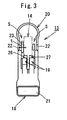
- Each synthetic resin clip 5 mounted to be capable of sliding on a lower crosswise bar portion 11 of the respective clip mounting portions 7, comprises of a pair of synthetic resin clip members 13, 13 disposed in an opposite position and a U shape of synthetic resin spring 5 mounted between the resin clip members 13, 13.
- the synthetic resin spring 14 is made of composite synthetic resin material comprising of high-density carbonate resin as a main component, the resin spring 14 having an inverted "U" shape that is thick at a bent-back portion 15 and becomes gradually thinner at the tips 16.
- An engaging portion 17 is formed on the inner surface of a claw portion oriented inwardly.
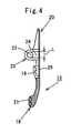
- the clip members 13, 13 are provided with nipping portions 18, 18 at one end portion to which a cushioning material, for example, sponge 21 is attached respectively. Further, the clip members 13, 13 are provided with receiving portions 19, 19 formed roughly on the middle of the respective interior portions of the respective clip members for engaging with the claw portions 17, 17 of the resin spring 14. Further, the clip members 13, 13 are provided with operation portions 20, 20 at the other ends of the clip members.
- a bracket bearing portion 23 for preventing the clip members 13 from flying apart is formed protruding into one of the gaps S (position biased in a lateral direction from the center of the clip member 13) between the surfaces of the abutting portions 22 at the left and right sides of the synthetic resin spring 14 mounted across each clip member 13,13.
- this fly-apart preventing portion that is to say, bracket bearing portions 23, 23 are formed on the rear faces of the respective clip members 13, 13 in a thin-plate shape, and have bearing spaces 24 extended inwardly.
- Each clip member 13 is provided with at least one mold part insertion/extraction opening 25 generally on the middle thereof, each of which leads to the bearing space 24 of the bracket bearing portion or fly-apart preventing portion 23.
- the mold part insertion/extraction opening 25 is formed in a quadrilateral with a width w roughly equal to the thickness t of the bracket bearing portion 23 and a length L roughly equal to the bearing space 24 (see Figure 2 ).
- bracket bearing portion 23 when viewed from the side the thus-formed bracket bearing portion 23 cooperates with the abutting portions 22 to clamp the pivot shaft 11 mounted on the clip mounting portions 7.
- reference numeral 26 in the drawings denotes a fly-apart preventing bar 23 for the synthetic resin spring 14, and is configured in the same manner as that in JP 2006-61365 A .
- the clip members 13, 13 are formed by a pair of male and female mold pieces (not shown), in order to form the receiving portions 19 for engaging with the engaging portion, i.e. claw portions 17 formed on the tip ends of the legs of the synthetic resin spring 14, window holes 27 for sliding the mold part through are disposed for removing the molded piece (the molded clip members) from the mold.
- At least one fly-apart preventing bar 26 is arranged to be extended across window holes 27, 27 in a longitudinal direction of the clip members 13, 13 and a slot is formed on the area between the receiving portions 17, 17 formed on the respective clip members 13, 13 in an opposite position of the corresponding fly-apart preventing bar 26. Further, the fly-apart preventing bars 16 are positioned so as to vertically cross with a thin width at a roughly middle position of the window holes. The upper and lower end portions thereof are respectively connected to the upper and lower edges of the window hole 27.
- the abutting portions 22 formed on the respective clip members 13 as configured above are disposed in position and brought to bear on the bearing surface around the pivot shaft portions 11 being interposed into the bracket bearing portion 23 so that the semicircular indent on its tip abuts the outer peripheral surface of the pivot shaft portion 11 having a circular cross-section, whereby the pair of clip members 13, 13 is pivotally supported on the pivot shaft portion 11.
- the synthetic resin clips 5, 5 as mentioned above are mounted on the pivot shaft portions, i.e. crosswise bar portion 11, 11 securely to the clip mounting portions 7, 7 wherein the respective pivot shaft portions 11 are interposed into the bearing spaces 24, 24 and simultaneously brought to bear on the bearing surface around the pivot shaft portions 11, 11 so that the pivot shaft portions 11 can slide to the left and right.
- the upper crossbar 10 and the pivot shaft portion 11 (lower crosswise bar portion) are inserted into the fitting hole 8 and the receiving hole 9 of the clip support 4 respectively.
- two synthetic resin clips 5 are mounted on either end portion of the clip mounting portion 7 on the hanger body 2, whereby a hanger comprising the synthetic resin clip are configured.
- the thus-configured clothes hanger 1 is entirely formed of synthetic resin, it can be passed through a metal detector (not shown) for detecting pins as is while clamping clothes etc. (e.g. a skirt) in the synthetic resin clips 5, 5.
- a metal detector not shown
- the clip members 13, 13 of the broken clip being subjected to a reaction of the spring breakage, those clip members 13, 13 are held by means of the pivot shaft secured in position without flying apart in pieces and also, the pieces of the broken spring are prevented from flying apart by the fly-apart preventing bar 26 through the window holes 27.
- injuries to the hands and face by the broken pieces of the synthetic resin spring 14 which flies apart can be eliminated.
- the synthetic resin clothes hanger 1 according to the present invention has all of its constituent parts formed of synthetic resin, clothes hung on the clothes hanger 1 can be checked as is for the presence of sewing pins, broken sewing machine needles and the like when checked by a metal detector for the presence of sewing pins, broken sewing machine needles and the like. Accordingly, a detection operation by a metal detector can be conducted quickly and accurately.
- bracket bearing portion 23 is formed in a thin plate shape from the rear face of the clip member 13 having a space 24 formed inwardly thereof, the bracket bearing portion is not limited to that configuration, and can have a hook shape, for example, as illustrated in Figure 5 .
- synthetic resin clip 5 is attached to the synthetic resin clothes hanger 1, the synthetic resin clip 5 is not limited to that configuration. It goes without saying that the synthetic resin clip 5 may be used by itself.
Landscapes
- Holders For Apparel And Elements Relating To Apparel (AREA)
- Clamps And Clips (AREA)
- Supports Or Holders For Household Use (AREA)
Claims (3)
- Pince en résine synthétique (1), comprenant :un arbre de pivotement (11) ;une paire d'éléments de pince en résine synthétique (13), opposés l'un à l'autre et montés sur l'arbre de pivotement (11) ; etun ressort en résine synthétique (14) ayant une forme en U inversée, repliée vers l'arrière au niveau d'une partie centrale (15), le ressort en résine synthétique état agencé sur les éléments de pince en résine synthétique (13) pour pousser des parties de pincement (18) formées au niveau d'une extrémité des éléments de pince en résine synthétique (13) les unes contre les autres par une force élastique, pour saisir un objet entre les parties de pincement des éléments de pince en résine synthétique, chacun des éléments de pince en résine synthétique (13) comprenant en outre les parties moulées d'une seule pièce ci-dessous :des parties de butée (22), agencées sur les deux parties de bordure latérale des éléments de pince en résine synthétique (13), les parties de butée (22) comportant une entaille semi-circulaire au niveau de la pointe butant contre la surface périphérique de l'arbre de pivotement, de sorte que l'élément de pince en résine synthétique respectif (13) est monté de manière pivotante sur l'arbre de pivotement (11) ;une partie empêchant une envolée (23), débordant vers l'intérieur à partir d'une face interne de l'élément de pince en résine synthétique respectif (13) et comportant un espace de palier (24) ; etune ouverture d'insertion/d'extraction des parties moulées (25), agencée en général au centre de chaque élément de pince (13), menant vers l'espace de palier (24) de la partie empêchant une envolée (23) ; dans laquellel'arbre de pivotement (11) est interposé de sorte que, lors d'une cassure du ressort en résine synthétique (14) et l'élément de pince respectif est exposé à une réaction de la cassure du ressort, l'élément de pince en résine synthétique respectif (13) et retenu sur l'arbre de pivotement par l'intermédiaire de la partie empêchant une envolée (23), son envolée étant empêchée.
- Pince en résine synthétique (1) selon la revendication 1, dans laquelle chaque élément de pince (13) comporte :une partie de réception (19) en vue d'un engagement dans le ressort en résine synthétique (14) ;un trou de fenêtre (27) sur un côté externe de la pince en résine synthétique (1), formé lors du retrait d'une pièce moulée utilisée pour former la partie de réception (19) ; etune barre empêchant une envolée (26), agencée à travers le trou de fenêtre (27), dans une direction longitudinale de l'élément de pince (13), une fente étant formée sur la partie de réception (19) de l'élément de pince (13) dans une position opposée à la barre empêchant une envolée correspondante.
- Cintre (1), comprenant:un corps de cintre (2) à extension horizontalun crochet rotatif (6) agencé sur le centre du corps du cintre ; etdes parties de montage de pinces (7), fournies sur chaque extrémité du corps du cintre, au moins deux pinces en résine synthétique (1) selon l'une quelconque des revendications 1 à 2 étant montées sur les parties de montage des pinces (7) en connectant l'arbre de pivotement (11) des pinces en résine synthétique respectives (1) à une partie de montage des pinces respectives (7), les éléments de l'arbre de pivotement (11) étant montés de manière amovible sur les parties de montage des pinces (7).
Applications Claiming Priority (1)
| Application Number | Priority Date | Filing Date | Title |
|---|---|---|---|
| JP2007043423A JP4612644B2 (ja) | 2007-02-23 | 2007-02-23 | 合成樹脂製クリップ及び合成樹脂製クリップ付きハンガー |
Publications (3)
| Publication Number | Publication Date |
|---|---|
| EP1961347A2 EP1961347A2 (fr) | 2008-08-27 |
| EP1961347A3 EP1961347A3 (fr) | 2009-10-07 |
| EP1961347B1 true EP1961347B1 (fr) | 2011-06-08 |
Family
ID=39433845
Family Applications (1)
| Application Number | Title | Priority Date | Filing Date |
|---|---|---|---|
| EP08250606A Not-in-force EP1961347B1 (fr) | 2007-02-23 | 2008-02-21 | Pince en plastique et cintre comportant une pince en plastique |
Country Status (6)
| Country | Link |
|---|---|
| US (1) | US7665640B2 (fr) |
| EP (1) | EP1961347B1 (fr) |
| JP (1) | JP4612644B2 (fr) |
| CN (1) | CN101248947B (fr) |
| AT (1) | ATE511779T1 (fr) |
| ES (1) | ES2366215T3 (fr) |
Families Citing this family (9)
| Publication number | Priority date | Publication date | Assignee | Title |
|---|---|---|---|---|
| USD776943S1 (en) * | 2015-04-15 | 2017-01-24 | Tracey Renee Busch Gunderson | Keepsake display |
| KR101809164B1 (ko) * | 2016-08-09 | 2017-12-14 | 인천대학교 산학협력단 | 탈착가능한 회전형 집게부를 갖는 옷걸이 |
| US10610014B2 (en) * | 2016-12-02 | 2020-04-07 | Lewis Joseph Smalligan | Clamp assembly |
| USD815845S1 (en) | 2017-05-12 | 2018-04-24 | Target Brands, Inc. | Hanger |
| USD831987S1 (en) | 2017-10-04 | 2018-10-30 | Target Brands, Inc. | Hanger |
| CN107874409A (zh) * | 2017-11-10 | 2018-04-06 | 安徽冠宜箱包有限公司 | 一种用于旅行拉杆箱的便携式晾挂装置 |
| USD1044488S1 (en) * | 2021-03-24 | 2024-10-01 | Sourcing Solutions International Limited | Plastic bottom clasp for paper hanger |
| USD964054S1 (en) * | 2021-03-25 | 2022-09-20 | Hangerlogic Inc. | Garment hanger with depending clips |
| IT202100010376A1 (it) * | 2021-04-23 | 2022-10-23 | Mainetti Spa | Pinza per appendini |
Family Cites Families (23)
| Publication number | Priority date | Publication date | Assignee | Title |
|---|---|---|---|---|
| US2525985A (en) * | 1949-02-18 | 1950-10-17 | C & W Tool Company | Removable garment supporting clip for clothes hangers |
| US2569371A (en) * | 1950-02-09 | 1951-09-25 | Cohen William | Pivoted spring clip |
| US2666240A (en) * | 1951-02-19 | 1954-01-19 | Maccaferri Mario | Clip for clothes racks |
| US2782482A (en) * | 1955-05-09 | 1957-02-26 | Hobar Inc | Hanging clip |
| US3950829A (en) * | 1974-06-03 | 1976-04-20 | Maurice Cohen | Hanger clip |
| US4335838A (en) * | 1980-04-07 | 1982-06-22 | Independent Products Company, Inc. | Skirt and trouser clip for hanger |
| US4701983A (en) * | 1985-07-09 | 1987-10-27 | Warmath John G | Clothes clip for a hanger |
| US4638930A (en) * | 1985-10-23 | 1987-01-27 | Batts, Inc. | Hanger leg mounting structure for a support rod |
| US4660750A (en) * | 1985-10-23 | 1987-04-28 | Batts, Inc. | Garment hanger with improved wire support |
| US4878276A (en) * | 1987-06-25 | 1989-11-07 | Peter G. A. Morrish | Spring clip |
| US4884727A (en) * | 1989-01-27 | 1989-12-05 | Batts, Inc. | Hanger with snap-on adjustable clips |
| DE9014462U1 (de) * | 1990-10-18 | 1992-02-20 | MAWA - Metallwarenfabrik Wagner GmbH, 8068 Pfaffenhofen | Klammernhalter |
| DE9300473U1 (de) * | 1993-01-15 | 1994-05-19 | Mawa - Metallwarenfabrik Wagner Gmbh, 85276 Pfaffenhofen | Klammer |
| US5289956A (en) * | 1993-02-03 | 1994-03-01 | Nicolean Petrou | Rod coupling construction for garment hangers |
| US5398854A (en) * | 1993-12-03 | 1995-03-21 | Batts, Inc. | Adjustable garment hanger |
| JP2581657B2 (ja) * | 1994-05-26 | 1997-02-12 | キンシ化学工業株式会社 | 組み立て式挾持具 |
| JP2956956B2 (ja) * | 1995-02-03 | 1999-10-04 | 英雄 三角 | 合成樹脂製クリップ |
| JPH1033351A (ja) * | 1996-07-22 | 1998-02-10 | Hideo Misumi | 合成樹脂製衣服用ハンガー |
| US5934525A (en) * | 1997-09-22 | 1999-08-10 | Batts, Inc. | Infinitely adjustable locking garment hanger |
| JP3408421B2 (ja) * | 1998-05-26 | 2003-05-19 | 英雄 三角 | 衣類吊下用クリップ |
| JP2001046215A (ja) * | 1999-08-09 | 2001-02-20 | Hideo Misumi | 合成樹脂製衣服用ハンガー |
| JP2004167141A (ja) * | 2002-11-22 | 2004-06-17 | Hideo Misumi | クリップ付きハンガー及びその製造方法 |
| JP4101216B2 (ja) * | 2004-08-26 | 2008-06-18 | 英雄 三角 | 合成樹脂製クリップ及び合成樹脂製クリップ付きハンガー |
-
2007
- 2007-02-23 JP JP2007043423A patent/JP4612644B2/ja active Active
-
2008
- 2008-02-21 US US12/071,474 patent/US7665640B2/en active Active
- 2008-02-21 EP EP08250606A patent/EP1961347B1/fr not_active Not-in-force
- 2008-02-21 AT AT08250606T patent/ATE511779T1/de not_active IP Right Cessation
- 2008-02-21 ES ES08250606T patent/ES2366215T3/es active Active
- 2008-02-22 CN CN2008100808732A patent/CN101248947B/zh not_active Expired - Fee Related
Also Published As
| Publication number | Publication date |
|---|---|
| JP2008206546A (ja) | 2008-09-11 |
| JP4612644B2 (ja) | 2011-01-12 |
| ATE511779T1 (de) | 2011-06-15 |
| US7665640B2 (en) | 2010-02-23 |
| CN101248947A (zh) | 2008-08-27 |
| ES2366215T3 (es) | 2011-10-18 |
| US20080201909A1 (en) | 2008-08-28 |
| CN101248947B (zh) | 2013-01-30 |
| EP1961347A3 (fr) | 2009-10-07 |
| EP1961347A2 (fr) | 2008-08-27 |
Similar Documents
| Publication | Publication Date | Title |
|---|---|---|
| EP1961347B1 (fr) | Pince en plastique et cintre comportant une pince en plastique | |
| US4706347A (en) | Hanger and clip therefor | |
| US20060042050A1 (en) | Synthetic resin clip and hanger with synthetic resin clips | |
| US5402558A (en) | Resilient clip | |
| US7178770B2 (en) | Article support device | |
| US5890634A (en) | Hanger with snap-on non-slip pads | |
| US9392864B2 (en) | Accessory fastening device | |
| JP6289483B2 (ja) | ファスナー用のスライダー及びその挿入の方法 | |
| JP2021523747A (ja) | 折り畳み機の物品クリップ、物品クリップアセンブリおよび折り畳み機の物品供給方法 | |
| JPH0528278U (ja) | カーテン吊り具 | |
| US6050462A (en) | Garment hanger with pinch clips | |
| KR101769372B1 (ko) | 옷걸이 어셈블리 | |
| JP3113984U (ja) | スカート吊りクリップ | |
| US7815080B2 (en) | Releasably lockable pinch grip hanger | |
| US2590881A (en) | Clothespin | |
| JP2956956B2 (ja) | 合成樹脂製クリップ | |
| US676273A (en) | Fastening device for buttons, hangers, &c. | |
| JP6334022B1 (ja) | クリップ | |
| US7441313B2 (en) | Spring clamp with hook | |
| JP3726157B2 (ja) | 合成樹脂製クリップ | |
| US20060226178A1 (en) | Clamp structure for garment hanger | |
| JP2006223705A (ja) | 折りたたみ式ハンガー | |
| TWI555489B (zh) | Clamp | |
| JPH056257Y2 (fr) | ||
| KR920002518Y1 (ko) | 화일표지용 서류철 파스너 |
Legal Events
| Date | Code | Title | Description |
|---|---|---|---|
| PUAI | Public reference made under article 153(3) epc to a published international application that has entered the european phase |
Free format text: ORIGINAL CODE: 0009012 |
|
| AK | Designated contracting states |
Kind code of ref document: A2 Designated state(s): AT BE BG CH CY CZ DE DK EE ES FI FR GB GR HR HU IE IS IT LI LT LU LV MC MT NL NO PL PT RO SE SI SK TR |
|
| AX | Request for extension of the european patent |
Extension state: AL BA MK RS |
|
| PUAL | Search report despatched |
Free format text: ORIGINAL CODE: 0009013 |
|
| AK | Designated contracting states |
Kind code of ref document: A3 Designated state(s): AT BE BG CH CY CZ DE DK EE ES FI FR GB GR HR HU IE IS IT LI LT LU LV MC MT NL NO PL PT RO SE SI SK TR |
|
| AX | Request for extension of the european patent |
Extension state: AL BA MK RS |
|
| 17P | Request for examination filed |
Effective date: 20100304 |
|
| 17Q | First examination report despatched |
Effective date: 20100415 |
|
| AKX | Designation fees paid |
Designated state(s): AT BE BG CH CY CZ DE DK EE ES FI FR GB GR HR HU IE IS IT LI LT LU LV MC MT NL NO PL PT RO SE SI SK TR |
|
| GRAP | Despatch of communication of intention to grant a patent |
Free format text: ORIGINAL CODE: EPIDOSNIGR1 |
|
| GRAS | Grant fee paid |
Free format text: ORIGINAL CODE: EPIDOSNIGR3 |
|
| GRAA | (expected) grant |
Free format text: ORIGINAL CODE: 0009210 |
|
| AK | Designated contracting states |
Kind code of ref document: B1 Designated state(s): AT BE BG CH CY CZ DE DK EE ES FI FR GB GR HR HU IE IS IT LI LT LU LV MC MT NL NO PL PT RO SE SI SK TR |
|
| REG | Reference to a national code |
Ref country code: GB Ref legal event code: FG4D |
|
| REG | Reference to a national code |
Ref country code: CH Ref legal event code: EP |
|
| REG | Reference to a national code |
Ref country code: IE Ref legal event code: FG4D |
|
| REG | Reference to a national code |
Ref country code: DE Ref legal event code: R096 Ref document number: 602008007382 Country of ref document: DE Effective date: 20110721 |
|
| REG | Reference to a national code |
Ref country code: NL Ref legal event code: VDEP Effective date: 20110608 |
|
| REG | Reference to a national code |
Ref country code: ES Ref legal event code: FG2A Ref document number: 2366215 Country of ref document: ES Kind code of ref document: T3 Effective date: 20111018 |
|
| PG25 | Lapsed in a contracting state [announced via postgrant information from national office to epo] |
Ref country code: HR Free format text: LAPSE BECAUSE OF FAILURE TO SUBMIT A TRANSLATION OF THE DESCRIPTION OR TO PAY THE FEE WITHIN THE PRESCRIBED TIME-LIMIT Effective date: 20110608 Ref country code: LT Free format text: LAPSE BECAUSE OF FAILURE TO SUBMIT A TRANSLATION OF THE DESCRIPTION OR TO PAY THE FEE WITHIN THE PRESCRIBED TIME-LIMIT Effective date: 20110608 Ref country code: NO Free format text: LAPSE BECAUSE OF FAILURE TO SUBMIT A TRANSLATION OF THE DESCRIPTION OR TO PAY THE FEE WITHIN THE PRESCRIBED TIME-LIMIT Effective date: 20110908 Ref country code: SE Free format text: LAPSE BECAUSE OF FAILURE TO SUBMIT A TRANSLATION OF THE DESCRIPTION OR TO PAY THE FEE WITHIN THE PRESCRIBED TIME-LIMIT Effective date: 20110608 |
|
| PG25 | Lapsed in a contracting state [announced via postgrant information from national office to epo] |
Ref country code: AT Free format text: LAPSE BECAUSE OF FAILURE TO SUBMIT A TRANSLATION OF THE DESCRIPTION OR TO PAY THE FEE WITHIN THE PRESCRIBED TIME-LIMIT Effective date: 20110608 Ref country code: SI Free format text: LAPSE BECAUSE OF FAILURE TO SUBMIT A TRANSLATION OF THE DESCRIPTION OR TO PAY THE FEE WITHIN THE PRESCRIBED TIME-LIMIT Effective date: 20110608 Ref country code: CY Free format text: LAPSE BECAUSE OF FAILURE TO SUBMIT A TRANSLATION OF THE DESCRIPTION OR TO PAY THE FEE WITHIN THE PRESCRIBED TIME-LIMIT Effective date: 20110608 Ref country code: GR Free format text: LAPSE BECAUSE OF FAILURE TO SUBMIT A TRANSLATION OF THE DESCRIPTION OR TO PAY THE FEE WITHIN THE PRESCRIBED TIME-LIMIT Effective date: 20110909 Ref country code: LV Free format text: LAPSE BECAUSE OF FAILURE TO SUBMIT A TRANSLATION OF THE DESCRIPTION OR TO PAY THE FEE WITHIN THE PRESCRIBED TIME-LIMIT Effective date: 20110608 Ref country code: FI Free format text: LAPSE BECAUSE OF FAILURE TO SUBMIT A TRANSLATION OF THE DESCRIPTION OR TO PAY THE FEE WITHIN THE PRESCRIBED TIME-LIMIT Effective date: 20110608 |
|
| PG25 | Lapsed in a contracting state [announced via postgrant information from national office to epo] |
Ref country code: NL Free format text: LAPSE BECAUSE OF FAILURE TO SUBMIT A TRANSLATION OF THE DESCRIPTION OR TO PAY THE FEE WITHIN THE PRESCRIBED TIME-LIMIT Effective date: 20110608 Ref country code: BE Free format text: LAPSE BECAUSE OF FAILURE TO SUBMIT A TRANSLATION OF THE DESCRIPTION OR TO PAY THE FEE WITHIN THE PRESCRIBED TIME-LIMIT Effective date: 20110608 |
|
| PG25 | Lapsed in a contracting state [announced via postgrant information from national office to epo] |
Ref country code: CZ Free format text: LAPSE BECAUSE OF FAILURE TO SUBMIT A TRANSLATION OF THE DESCRIPTION OR TO PAY THE FEE WITHIN THE PRESCRIBED TIME-LIMIT Effective date: 20110608 Ref country code: EE Free format text: LAPSE BECAUSE OF FAILURE TO SUBMIT A TRANSLATION OF THE DESCRIPTION OR TO PAY THE FEE WITHIN THE PRESCRIBED TIME-LIMIT Effective date: 20110608 Ref country code: IS Free format text: LAPSE BECAUSE OF FAILURE TO SUBMIT A TRANSLATION OF THE DESCRIPTION OR TO PAY THE FEE WITHIN THE PRESCRIBED TIME-LIMIT Effective date: 20111008 Ref country code: PT Free format text: LAPSE BECAUSE OF FAILURE TO SUBMIT A TRANSLATION OF THE DESCRIPTION OR TO PAY THE FEE WITHIN THE PRESCRIBED TIME-LIMIT Effective date: 20111010 |
|
| PG25 | Lapsed in a contracting state [announced via postgrant information from national office to epo] |
Ref country code: PL Free format text: LAPSE BECAUSE OF FAILURE TO SUBMIT A TRANSLATION OF THE DESCRIPTION OR TO PAY THE FEE WITHIN THE PRESCRIBED TIME-LIMIT Effective date: 20110608 Ref country code: RO Free format text: LAPSE BECAUSE OF FAILURE TO SUBMIT A TRANSLATION OF THE DESCRIPTION OR TO PAY THE FEE WITHIN THE PRESCRIBED TIME-LIMIT Effective date: 20110608 Ref country code: SK Free format text: LAPSE BECAUSE OF FAILURE TO SUBMIT A TRANSLATION OF THE DESCRIPTION OR TO PAY THE FEE WITHIN THE PRESCRIBED TIME-LIMIT Effective date: 20110608 |
|
| PLBE | No opposition filed within time limit |
Free format text: ORIGINAL CODE: 0009261 |
|
| STAA | Information on the status of an ep patent application or granted ep patent |
Free format text: STATUS: NO OPPOSITION FILED WITHIN TIME LIMIT |
|
| 26N | No opposition filed |
Effective date: 20120309 |
|
| PG25 | Lapsed in a contracting state [announced via postgrant information from national office to epo] |
Ref country code: DK Free format text: LAPSE BECAUSE OF FAILURE TO SUBMIT A TRANSLATION OF THE DESCRIPTION OR TO PAY THE FEE WITHIN THE PRESCRIBED TIME-LIMIT Effective date: 20110608 |
|
| REG | Reference to a national code |
Ref country code: DE Ref legal event code: R097 Ref document number: 602008007382 Country of ref document: DE Effective date: 20120309 |
|
| PG25 | Lapsed in a contracting state [announced via postgrant information from national office to epo] |
Ref country code: MC Free format text: LAPSE BECAUSE OF NON-PAYMENT OF DUE FEES Effective date: 20120229 |
|
| REG | Reference to a national code |
Ref country code: CH Ref legal event code: PL |
|
| PG25 | Lapsed in a contracting state [announced via postgrant information from national office to epo] |
Ref country code: CH Free format text: LAPSE BECAUSE OF NON-PAYMENT OF DUE FEES Effective date: 20120229 Ref country code: LI Free format text: LAPSE BECAUSE OF NON-PAYMENT OF DUE FEES Effective date: 20120229 |
|
| REG | Reference to a national code |
Ref country code: IE Ref legal event code: MM4A |
|
| REG | Reference to a national code |
Ref country code: DE Ref legal event code: R119 Ref document number: 602008007382 Country of ref document: DE Effective date: 20120901 |
|
| PG25 | Lapsed in a contracting state [announced via postgrant information from national office to epo] |
Ref country code: IE Free format text: LAPSE BECAUSE OF NON-PAYMENT OF DUE FEES Effective date: 20120221 |
|
| PG25 | Lapsed in a contracting state [announced via postgrant information from national office to epo] |
Ref country code: BG Free format text: LAPSE BECAUSE OF FAILURE TO SUBMIT A TRANSLATION OF THE DESCRIPTION OR TO PAY THE FEE WITHIN THE PRESCRIBED TIME-LIMIT Effective date: 20110908 Ref country code: DE Free format text: LAPSE BECAUSE OF NON-PAYMENT OF DUE FEES Effective date: 20120901 |
|
| PG25 | Lapsed in a contracting state [announced via postgrant information from national office to epo] |
Ref country code: MT Free format text: LAPSE BECAUSE OF FAILURE TO SUBMIT A TRANSLATION OF THE DESCRIPTION OR TO PAY THE FEE WITHIN THE PRESCRIBED TIME-LIMIT Effective date: 20110608 |
|
| PG25 | Lapsed in a contracting state [announced via postgrant information from national office to epo] |
Ref country code: TR Free format text: LAPSE BECAUSE OF FAILURE TO SUBMIT A TRANSLATION OF THE DESCRIPTION OR TO PAY THE FEE WITHIN THE PRESCRIBED TIME-LIMIT Effective date: 20110608 |
|
| PG25 | Lapsed in a contracting state [announced via postgrant information from national office to epo] |
Ref country code: LU Free format text: LAPSE BECAUSE OF NON-PAYMENT OF DUE FEES Effective date: 20120221 |
|
| PG25 | Lapsed in a contracting state [announced via postgrant information from national office to epo] |
Ref country code: HU Free format text: LAPSE BECAUSE OF FAILURE TO SUBMIT A TRANSLATION OF THE DESCRIPTION OR TO PAY THE FEE WITHIN THE PRESCRIBED TIME-LIMIT Effective date: 20080221 |
|
| REG | Reference to a national code |
Ref country code: FR Ref legal event code: PLFP Year of fee payment: 9 |
|
| REG | Reference to a national code |
Ref country code: FR Ref legal event code: PLFP Year of fee payment: 10 |
|
| REG | Reference to a national code |
Ref country code: FR Ref legal event code: PLFP Year of fee payment: 11 |
|
| PGFP | Annual fee paid to national office [announced via postgrant information from national office to epo] |
Ref country code: GB Payment date: 20211230 Year of fee payment: 15 |
|
| PGFP | Annual fee paid to national office [announced via postgrant information from national office to epo] |
Ref country code: IT Payment date: 20220111 Year of fee payment: 15 Ref country code: FR Payment date: 20220118 Year of fee payment: 15 Ref country code: ES Payment date: 20220304 Year of fee payment: 15 |
|
| GBPC | Gb: european patent ceased through non-payment of renewal fee |
Effective date: 20230221 |
|
| PG25 | Lapsed in a contracting state [announced via postgrant information from national office to epo] |
Ref country code: GB Free format text: LAPSE BECAUSE OF NON-PAYMENT OF DUE FEES Effective date: 20230221 |
|
| PG25 | Lapsed in a contracting state [announced via postgrant information from national office to epo] |
Ref country code: IT Free format text: LAPSE BECAUSE OF NON-PAYMENT OF DUE FEES Effective date: 20230221 Ref country code: GB Free format text: LAPSE BECAUSE OF NON-PAYMENT OF DUE FEES Effective date: 20230221 Ref country code: FR Free format text: LAPSE BECAUSE OF NON-PAYMENT OF DUE FEES Effective date: 20230228 |
|
| REG | Reference to a national code |
Ref country code: ES Ref legal event code: FD2A Effective date: 20240405 |
|
| PG25 | Lapsed in a contracting state [announced via postgrant information from national office to epo] |
Ref country code: ES Free format text: LAPSE BECAUSE OF NON-PAYMENT OF DUE FEES Effective date: 20230222 |
|
| PG25 | Lapsed in a contracting state [announced via postgrant information from national office to epo] |
Ref country code: ES Free format text: LAPSE BECAUSE OF NON-PAYMENT OF DUE FEES Effective date: 20230222 |