EP1961358A2 - Système robot nettoyeur doté d'un robot nettoyeur et d'une station d'accueil - Google Patents
Système robot nettoyeur doté d'un robot nettoyeur et d'une station d'accueil Download PDFInfo
- Publication number
- EP1961358A2 EP1961358A2 EP08151359A EP08151359A EP1961358A2 EP 1961358 A2 EP1961358 A2 EP 1961358A2 EP 08151359 A EP08151359 A EP 08151359A EP 08151359 A EP08151359 A EP 08151359A EP 1961358 A2 EP1961358 A2 EP 1961358A2
- Authority
- EP
- European Patent Office
- Prior art keywords
- dust
- collecting chamber
- robot cleaner
- dust collecting
- connection path
- Prior art date
- Legal status (The legal status is an assumption and is not a legal conclusion. Google has not performed a legal analysis and makes no representation as to the accuracy of the status listed.)
- Granted
Links
Images



Classifications
-
- A—HUMAN NECESSITIES
- A47—FURNITURE; DOMESTIC ARTICLES OR APPLIANCES; COFFEE MILLS; SPICE MILLS; SUCTION CLEANERS IN GENERAL
- A47L—DOMESTIC WASHING OR CLEANING; SUCTION CLEANERS IN GENERAL
- A47L9/00—Details or accessories of suction cleaners, e.g. mechanical means for controlling the suction or for effecting pulsating action; Storing devices specially adapted to suction cleaners or parts thereof; Carrying-vehicles specially adapted for suction cleaners
- A47L9/28—Installation of the electric equipment, e.g. adaptation or attachment to the suction cleaner; Controlling suction cleaners by electric means
-
- A—HUMAN NECESSITIES
- A47—FURNITURE; DOMESTIC ARTICLES OR APPLIANCES; COFFEE MILLS; SPICE MILLS; SUCTION CLEANERS IN GENERAL
- A47L—DOMESTIC WASHING OR CLEANING; SUCTION CLEANERS IN GENERAL
- A47L9/00—Details or accessories of suction cleaners, e.g. mechanical means for controlling the suction or for effecting pulsating action; Storing devices specially adapted to suction cleaners or parts thereof; Carrying-vehicles specially adapted for suction cleaners
- A47L9/10—Filters; Dust separators; Dust removal; Automatic exchange of filters
- A47L9/106—Dust removal
-
- A—HUMAN NECESSITIES
- A47—FURNITURE; DOMESTIC ARTICLES OR APPLIANCES; COFFEE MILLS; SPICE MILLS; SUCTION CLEANERS IN GENERAL
- A47L—DOMESTIC WASHING OR CLEANING; SUCTION CLEANERS IN GENERAL
- A47L9/00—Details or accessories of suction cleaners, e.g. mechanical means for controlling the suction or for effecting pulsating action; Storing devices specially adapted to suction cleaners or parts thereof; Carrying-vehicles specially adapted for suction cleaners
-
- A—HUMAN NECESSITIES
- A47—FURNITURE; DOMESTIC ARTICLES OR APPLIANCES; COFFEE MILLS; SPICE MILLS; SUCTION CLEANERS IN GENERAL
- A47L—DOMESTIC WASHING OR CLEANING; SUCTION CLEANERS IN GENERAL
- A47L2201/00—Robotic cleaning machines, i.e. with automatic control of the travelling movement or the cleaning operation
-
- A—HUMAN NECESSITIES
- A47—FURNITURE; DOMESTIC ARTICLES OR APPLIANCES; COFFEE MILLS; SPICE MILLS; SUCTION CLEANERS IN GENERAL
- A47L—DOMESTIC WASHING OR CLEANING; SUCTION CLEANERS IN GENERAL
- A47L2201/00—Robotic cleaning machines, i.e. with automatic control of the travelling movement or the cleaning operation
- A47L2201/02—Docking stations; Docking operations
- A47L2201/024—Emptying dust or waste liquid containers
Definitions
- the present invention relates to a cleaner More particularly, the present invention relates to a robot cleaner system having a docking station used to remove dust by sucking the dust collected in a robot cleaner
- a cleaner is an appliance that cleans a room by removing impurities from the room.
- a vacuum cleaner that sucks impurities using suction force of a vacuum section is mainly used.
- a robot cleaner which detects and removes impurities from a floor while moving along the floor according to an automatic traveling function, has been developed.
- the robot cleaner constitutes a robot cleaner system together with a docking station, which is located in a predetermined place of a room to electrically charge the robot cleaner or to remove dust collected in the robot cleaner.
- the robot cleaner system includes a robot cleaner and a docking station having a suction unit to suck dust.
- a suction port is formed at a lower portion of the robot cleaner to suck dust and a brush is rotatably installed in the suction port to brush dust from a floor.
- the docking station is provided with a support having an inclined surface to allow the robot cleaner to move onto the docking station.
- a suction port is formed at one side of the inclined surface to suck dust from the robot cleaner
- the robot cleaner docks with the docking station after the robot cleaner has been placed on the inclined surface of the docking station having a predetermined height. Therefore, the docking operation of the robot cleaner is not easy. Thus, a complex structure is necessary to precisely guide the robot cleaner onto the docking position.
- the structure of the support installed in the docking station is inadvantageous because the support interferes with the moving function of the docking station, so the docking station cannot be separately used as a manual cleaner
- a robot cleaner system including a robot cleaner having superior functions of sucking dust and exhausting dust to a docking station.
- Another aspect of the present embodiment is to provide a robot cleaner system capable of easily performing a docking operation between a robot cleaner and a docking station.
- Still another aspect of the present embodiment is to provide a robot cleaner system including a docking station, which is equipped with a moving function so that the docking station can be separately used as a manual cleaner.
- a robot cleaner system including: a robot cleaner; and a docking station to receive dust collected in the robot cleaner, wherein the robot cleaner includes: a dust suction port to suck dust; a dust collecting chamber to collect dust introduced through the dust suction port; a dust exhaust port to exhaust dust collected in the dust collecting chamber to the docking station; a connection path extending from the dust suction port to the dust exhaust port in adjacent to the dust collecting chamber; and a valve device provided between the connection path and the dust collecting chamber, an opening/closing of the valve device allowing the dust collecting chamber to selectively communicate with the dust suction port or the dust exhaust port according to a pressure difference between the dust collecting chamber and the connection path.
- the valve device may include a suction valve, which is opened when dust is sucked through the dust suction port, and an exhaust valve, which is opened when dust is exhausted through the dust exhaust port.
- the robot cleaner system may further includes an air guide provided between the suction valve and the exhaust valve to define the dust collecting chamber and the connection path.
- the exhaust valve may be provided at a lower portion of the dust collecting chamber, and the exhaust valve may be closed when a pressure of the dust collecting chamber is lower than a pressure of the connection path.
- the suction valve may be closed when a pressure of the connection path is lower than a pressure of the dust collecting chamber.
- the exhaust valve may include a first valve member having a first side rotatably fixed and a second side pivotably rotated toward the connection path to open/close a path between the connection path and the dust collecting chamber.
- the suction valve may include a second valve member having a first side rotatably fixed by means of a pivot pin and a second side pivotably rotated toward the dust collecting chamber to open/close a path between the connection path and the dust collecting chamber.
- the path between the connection path and the dust collecting chamber may be opened in a normal state due to a weight thereof.
- connection path may be closed in a normal state due to a weight thereof.
- the robot cleaner may further include a valve unit that opens the dust exhaust port when the robot cleaner docks with the docking station.
- the robot cleaner may further include a first dust box to collect dust, the dust collecting chamber, the connection path and the valve device being provided in the first dust box.
- a check valve which may be opened when a suction force is applied to the connection path, may be installed in the dust suction port to prevent dust from flowing back, and the check valve may include a third valve member, an upper portion of the third valve member being rotatably fixed so that the third valve member is able to close the dust suction port due to a weight thereof.
- a robot cleaner system including: a robot cleaner having a first dust box to collect dust; and a docking station to receive dust collected in the robot cleaner, wherein the first dust box includes: a dust suction port to suck dust; a dust collecting chamber to collect dust introduced through the dust suction port; a dust exhaust port to exhaust dust collected in the dust collecting chamber to the docking station; a connection path extending from the dust suction port to the dust exhaust port in adjacent to the dust collecting chamber; and a valve device provided between the connection path and the dust collecting chamber, an opening/closing of the valve device allowing the dust collecting chamber to selectively communicate with the dust suction port or the dust exhaust port according to a pressure difference between the dust collecting chamber and the connection path.
- the valve device may include a suction valve, which may be opened when dust is sucked through the dust suction port, and an exhaust valve, which may be opened when dust is exhausted through the dust exhaust port.
- the robot cleaner system may further includes an air guide provided between the suction valve and the exhaust valve to define the dust collecting chamber and the connection path.
- the exhaust valve may include a first valve member having a first side rotatably fixed and a second side pivotably rotated toward the connection path to open/close a path between the connection path and the dust collecting chamber.
- the suction valve may include a second valve member having a first side rotatably fixed and a second side pivotably rotated toward the dust collecting chamber to open/close a path between the connection path and the dust collecting chamber.
- a robot cleaner which docks with a docking station to exhaust dust to the docking station, including: a dust box to collect dust, wherein the dust box includes: a dust suction port sucking dust; a dust collecting chamber collecting dust introduced through the dust suction port; a dust exhaust port exhausting dust collected in the dust collecting chamber to the docking station; a connection path extending from the dust suction port to the dust exhaust port adjacent to the dust collecting chamber; and a valve device provided between the connection path and the dust collecting chamber such that the dust collecting chamber selectively communicates with the dust suction port or the dust exhaust port according to a pressure difference between the dust collecting chamber and the connection path.
- the valve device may include a suction valve, which may be opened when dust is sucked through the dust suction port, and an exhaust valve, which may be opened when dust is exhausted through the dust exhaust port.
- the exhaust valve may include a first valve member having a first side rotatably fixed and a second side pivotably rotated toward the connection path to apen/close a path between the connection path and the dust collecting chamber.
- the suction valve may include a second valve member having a first side rotatably fixed and a second side pivotably rotated toward the dust collecting chamber to open/close a path between the connection path and the dust collecting chamber.
- the exhaust valve may be provided at a lower portion of the dust collecting chamber, and the robot cleaner may further include a valve unit that opens the dust exhaust port when the robot cleaner docks with the docking station.
- a robot cleaner system including a robot cleaner including: a first blower, a dust collecting chamber collecting dust when the first blower is operated, a connection path selectively communicating with the dust collecting chamber, and a valve device provided between the connection path and the dust collecting chamber, an opening/closing of the valve device allowing the connection path to selectively communicate with the dust collecting chamber; and a docking station including a second blower, the docking station receiving dust from the dust collecting chamber when the robot cleaner is docked with the docking station and the second blower is operated.
- the valve device may be opened/clased according to a pressure difference between the dust collecting chamber and the connection path.
- FIG. 1 is a perspective view showing an external appearance of a robot cleaner system according to an embodiment
- FIG. 2 is a partial sectional view showing an internal structure of a robot cleaner system shown in FIG. 1 in a state in which a robot cleaner docks with a docking station
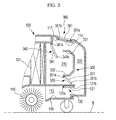
- FIG. 3 is a sectional view showing a fluid path formed in a robot cleaner shown in FIG. 1 when the robot cleaner sucks dust
- FIG. 4 is a partial sectional view showing a fluid path formed in a robot cleaner shown in FIG. 1 when the robot cleaner exhausts dust to a docking station.
- the robot cleaner system includes a robot cleaner 100 having a robot body 110 and a first dust box 300 installed in the robot body 110 to collect dust introduced into the robot body 100, and a docking station 200 that removes dust by sucking dust stored in the first dust box 300 when the robot cleaner 100 docks with the docking station 200.
- the robot cleaner 100 automatically moves on a floor bottom to clean the floor bottom, If dust has collected in the first dust box 300 to a predetermined level, the robot cleaner 100 returns to the docking station 200 to exhaust dust.
- the robot cleaner 100 has a first blower 130 installed in the robot body 110 to generate suction force to suck dust.
- a filter 101 is disposed between the first blower 130 and the first dust box 300 in order to filter dust from air, thereby preventing dust from being introduced into the first blower 130.
- the first blower 130 includes a suction motor and a blowing fan which is rotated by the suction motor.
- a sensor (not shown) is installed in the robot body 110 to detect an amount of dust collected in the first dust box 300.
- a pair of driving wheels 111 is installed at a lower portion of the robot body 110 to allow the robot cleaner 100 to move.
- the driving wheels 111 are selectively driven by a driving motor (not shown) such that the robot cleaner 100 can move in a predetermined direction to clean work.
- the robot cleaner 100 has a dust suction port 112, which is formed at a lower portion of the robot body 110 to suck dust from a bottom B of a cleaning region, an air exhaust port 113 to exhaust air, which is sucked by the first blower 130, out of the robot body 110, and a dust exhaust port 114 formed on an upper surface of the robot body 110 to exhaust dust to the docking station 200 when the robot cleaner 100 docks with the docking station 200.
- a brush 115 is rotatably installed adjacent to the dust suction port 112 to brush dust from the bottom B, and a suction path 116 is formed between the dust suction port 112 and the first dust box 300 such that the dust suction port 112 can communicate with the first dust box 300.
- the docking station 200 includes a station body 210, a second blower 220 installed in the station body 210 to generate suction force to suck dust, and a second dust box 230 provided in the station body 210 to collect dust therein.
- the second blower 220 includes a fan motor (not shown) and a blowing fan (not shown) rotated by the fan motor.
- An air exhaust port 201 is formed in the docking station 200 in order to exhaust air sucked by the second blower 220 to the exterior.
- a dust suction port 211 is formed in the station body 210 and corresponds with the dust exhaust port 114 of the robot cleaner 100 in order to suck dust from the robot cleaner 100.
- a dust suction path 212 is formed between the dust suction port 211 and the second dust box 230. Therefore, when the robot cleaner 100 docks with the docking station 200, the dust exhaust port 114 is adjacent to the dust suction port 211 to communicate with the dust suction port 211.
- the first dust box 300 is formed in the robot cleaner 100 in order to collect dust therein during the cleaning process.
- Fluid paths and valve devices are provided in the first dust box 300 in order to allow dust to be introduced into the robot cleaner 100 through the dust suction port 112 during the cleaning mode of the robot cleaner 100 and to exhaust dust to the docking station 200 through the dust exhaust port 114 when the robot cleaner 100 docks with the docking station 200.
- a dust collecting chamber 310 is formed at one side of the first dust box 300 to receive and collect dust therein.
- One side of the dust collecting chamber 310 communicates with both the filter 101 and the first blower 130.
- the dust exhaust port 114 is provided at an upper portion of the first dust box 300 and the suction path 116 is formed at a lower portion of the first dust box 300 to suck dust from the exterior.
- a connection path 320 is formed between the suction path 116 and the dust exhaust port 114.
- An air guide 330 and a valve device are provided between the dust collecting chamber 310 of the first dust box 300 and the connection path 320 to define two space sections in the first dust box 300.
- the valve device includes a suction valve 340 and an exhaust valve 350.
- the air guide 330 is provided between the suction valve 340 and the exhaust valve 350.
- the suction valve 340 opens the space between the connection path 320 and the dust collecting chamber 310 to allow dust to be collected in the dust collecting chamber 310 through the dust suction port 112 and the connection path 320.
- the suction valve 340 closes the space between the connection path 320 and the dust collecting chamber 310.
- the exhaust valve 350 is maintained in a closed state when dust is sucked through the dust suction port 112 and is maintained in an opened state when dust is exhausted to the docking station 200 in a state in which the robot cleaner 100 docks with the docking station 200.
- the exhaust valve 350 and the suction valve 340 are opened/closed when sucking/exhausting dust due to a pressure difference between the dust collecting chamber 310 and the connection path 320.
- Such an opening/closing operation is achieved by first and second valve members 351 and 341, which are pivotably moved about one side end portion thereof.
- an upper end portion of the second valve member 341 is fixed to an upper portion of the first dust box by a pivot pin 341a, and a lower end portion 341b of the second valve member 341 is pivotably rotated about the pivot pin 341 a.
- the lower end portion 341 b of the second valve member 341 makes contact with an upper end portion 331 of the air guide 330, the path between the connection path 320 and the dust collecting chamber 310 is closed.
- the suction valve 340 is opened when there is no pressure difference between the dust collecting chamber 310 and the connection path 320 (normal state) and when dust is sucked into the dust collecting chamber 310 caused by a suction force of the first blower 130.
- the second valve member 341 In the docking state, if the second blower 220 of the docking station 200 operates to apply suction force to the connection path 320, the second valve member 341 is pivotably rotated about the pivot pin 341 a due to air flow flowing forward to the connection path 320 from the dust collecting chamber 310, so that the lower end portion 341 b of the second valve member 341 moves up and makes contact with the air guide 330. Thus, the path between the dust collecting chamber 310 and the connection path 320 is closed.
- the structure and operation of the exhaust valve 350 are basically identical to those of the suction valve 340. If the suction valve 340 is opened, the exhaust valve 350 is closed. In addition, if the suction valve 340 is closed, the exhaust valve 350 is opened.
- An upper end portion of the first valve member 351 is coupled to a lower end portion 332 of the air guide 330 by means of a pivot pin 351a.
- a lower end portion 351b of the first valve member 351 makes contact with a bottom of the dust collecting chamber 310, the path between the dust collecting chamber 310 and the connection path 320 is closed.
- the first valve member 351 is pivotably rotated about the pivot pin 351 a, the lower end portion 351 b of the first valve member 351 makes contact with the bottom of the dust collecting chamber 310, so that the rotation of the first valve member 351 toward the dust collecting chamber 310 may be limited.
- the first valve member 351 in the normal state in which there is no pressure difference between the dust collecting chamber 310 and the connection path 320, or when dust is sucked into the dust collecting chamber 310 caused by a suction force of the first blower 130, the first valve member 351 is maintained in the closed state.
- the second blower 220 of the docking station 200 operates to apply a suction force to the connection path 320
- the first valve member 351 is pivotably rotated about the pivot pin 351 a due to air flow flowing forward to the connection path 320 from the dust collecting chamber 310, so that the lower end portion 351 b of the first valve member 351 moves upward.
- the path between the dust collecting chamber 310 and the connection path 320 is opened.
- the exhaust valve 350 is located below the suction valve 340, i.e., the exhaust valve 350 is installed at the lower portion of the dust collecting chamber 310. Since dust is primarily collected in the lower portion of the dust collecting chamber 310, if the lower portion of the dust collecting chamber 310 is opened when dust collected in the dust collecting chamber 310 is exhausted to the docking station, dust can be effectively exhausted.
- a valve unit 360 is installed in the dust exhaust port 114. Similar to the suction valve 340 and the exhaust valve 350, the valve unit 360 includes a fourth valve member 361, which is pivotably rotated about a pivot pin 361a provided at one side of the fourth valve member 361 in order to open/close the connection path 320 relative to the exterior.
- a lower end portion 361 b of the fourth valve member 361 makes contact with a stepped portion 117 formed at the upper portion of the first dust box 300, thereby closing the dust exhaust port 114.
- the fourth valve member 361 opens the dust exhaust port 114.
- a check valve 120 is installed in the suction path 116.
- the check valve 120 includes a third valve member 121 provided at one side thereof with a pivot pin 121 a. The third valve member 121 is pivotably rotated about the pivot pin 121 a to open/close the suction path 116.
- an upper end portion of the third valve member 121 is coupled to the suction path 116 by the pivot pin 121 a and a lower end portion 121 b of the third valve member 121 makes contact with a lower portion of the suction path 116 such that the third valve member 121 can be closed in the normal state, thereby preventing dust from flowing back.
- the third valve member 121 is opened in the cleaning mode in which suction force is applied to the connection path 320, or when dust collected in the dust collecting chamber 310 is exhausted.
- the process of collecting dust in the first dust box 300 will be explained. If the first blower 130 operates in the cleaning mode of the robot cleaner 100, suction force is applied to the dust collecting chamber 310, so that the suction valve 340 is opened and the exhaust valve 350 is closed. Thus, a fluid path extending from the suction path 116 to the dust collecting chamber 310 through the connection path 320 is formed in the robot cleaner 100. Accordingly, suction force is applied to the dust suction port 112, so that the check valve 120 is opened.
- suction force opens the exhaust valve 350, so that the dust collecting chamber 310 communicates with the connection path 320.
- the check valve 120 of the suction path 116 is also opened due to such suction force, so that external air is introduced through the suction port 112.
- connection path 320 air introduced into the dust collecting chamber 310 through the filter 101 is discharged to the connection path 320 together with dust collected in the dust collecting chamber 310.
- dust remaining in the suction path 116 is also introduced into the connection path 320 together with air which is introduced through the dust suction port 112, so that dust is collected in the second dust box 230 through the dust suction port 211 of the docking station 200 and the dust exhaust path 212.
- the robot cleaner in the cleaning mode, the robot cleaner represents superior suction efficiency when collecting dust in the first dust box.
- the robot cleaner in the docking state, can effectively exhaust dust collected in the first dust box to the docking station.
- the upper portion of the robot cleaner docks with the docking station, so that a docking operation can be easily achieved.
- the robot cleaner can be used as a manual cleaner.
Landscapes
- Engineering & Computer Science (AREA)
- Mechanical Engineering (AREA)
- Electric Suction Cleaners (AREA)
- Electric Vacuum Cleaner (AREA)
Applications Claiming Priority (1)
| Application Number | Priority Date | Filing Date | Title |
|---|---|---|---|
| KR1020070019128A KR101204440B1 (ko) | 2007-02-26 | 2007-02-26 | 로봇청소기와 도킹스테이션을 구비한 로봇청소기 시스템 |
Publications (3)
| Publication Number | Publication Date |
|---|---|
| EP1961358A2 true EP1961358A2 (fr) | 2008-08-27 |
| EP1961358A3 EP1961358A3 (fr) | 2008-09-03 |
| EP1961358B1 EP1961358B1 (fr) | 2012-04-18 |
Family
ID=39473217
Family Applications (1)
| Application Number | Title | Priority Date | Filing Date |
|---|---|---|---|
| EP08151359A Expired - Fee Related EP1961358B1 (fr) | 2007-02-26 | 2008-02-13 | Système robot nettoyeur doté d'un robot nettoyeur et d'une station d'accueil |
Country Status (4)
| Country | Link |
|---|---|
| US (1) | US7891045B2 (fr) |
| EP (1) | EP1961358B1 (fr) |
| KR (1) | KR101204440B1 (fr) |
| CN (1) | CN101254080A (fr) |
Cited By (15)
| Publication number | Priority date | Publication date | Assignee | Title |
|---|---|---|---|---|
| EP2380475A3 (fr) * | 2007-03-27 | 2013-08-14 | Samsung Electronics Co., Ltd. | Robot nettoyeur doté d'un collecteur de poussière amélioré |
| EP2263506A3 (fr) * | 2009-06-19 | 2013-12-04 | Samsung Electronics Co., Ltd. | Robot de nettoyage |
| EP2449939A3 (fr) * | 2010-11-03 | 2014-04-02 | Samsung Electronics Co., Ltd. | Robot nettoyeur, station d'échappement automatique et système de robot nettoyeur doté de celle-ci |
| EP2440100A4 (fr) * | 2009-06-10 | 2016-06-01 | Samsung Electronics Co Ltd | Appareil de nettoyage et procédé de dépoussiérage mettant en oeuvre ledit appareil |
| CN105640441A (zh) * | 2014-11-10 | 2016-06-08 | 江苏美的清洁电器股份有限公司 | 扫地机器人 |
| WO2016093911A1 (fr) * | 2014-12-10 | 2016-06-16 | Irobot Corporation | Évacuation de débris pour robots de nettoyage |
| US10463215B2 (en) | 2014-12-24 | 2019-11-05 | Irobot Corporation | Evacuation station |
| US20200405107A1 (en) * | 2019-06-25 | 2020-12-31 | Samsung Electronics Co., Ltd. | Robot cleaner, station, and cleaning system |
| US20210330167A1 (en) * | 2020-04-22 | 2021-10-28 | Omachron Intellectual Property Inc. | Robotic vacuum cleaner and docking station for a robotic vacuum cleaner |
| EP3860417A4 (fr) * | 2018-12-14 | 2021-11-24 | Samsung Electronics Co., Ltd. | Robot nettoyeur, station et système de nettoyage |
| US11272820B2 (en) * | 2016-11-30 | 2022-03-15 | Toshiba Lifestyle Products & Services Corporation | Electric vacuum cleaner device |
| US11406236B2 (en) * | 2017-06-23 | 2022-08-09 | Toshiba Lifestyle Products & Services Corporation | Electric vacuum cleaning apparatus |
| US11452424B2 (en) * | 2017-06-22 | 2022-09-27 | Toshiba Lifestyle Products & Services Corporation | Electric vacuum cleaner apparatus |
| WO2023040526A1 (fr) * | 2021-09-17 | 2023-03-23 | Yunjing Intelligence Technology (Dongguan) Co., Ltd. | Robot de nettoyage |
| US12029379B2 (en) | 2020-04-22 | 2024-07-09 | Omachron Intellectual Property Inc. | Robotic vacuum cleaner with dirt enclosing member and method of using the same |
Families Citing this family (101)
| Publication number | Priority date | Publication date | Assignee | Title |
|---|---|---|---|---|
| JP2008520394A (ja) | 2004-11-23 | 2008-06-19 | エス.シー. ジョンソン アンド サン、インコーポレイテッド | 表面床クリーニングと組み合わせた空気の浄化を提供する装置および方法 |
| USD586959S1 (en) * | 2008-05-09 | 2009-02-17 | Irobot Corporation | Autonomous coverage robot |
| US8774970B2 (en) | 2009-06-11 | 2014-07-08 | S.C. Johnson & Son, Inc. | Trainable multi-mode floor cleaning device |
| DE102009034955B4 (de) | 2009-07-28 | 2023-06-15 | Vorwerk & Co. Interholding Gmbh | Selbsttätig verfahrbares Bodenstaub-Aufsammelgerät |
| KR101483541B1 (ko) * | 2010-07-15 | 2015-01-19 | 삼성전자주식회사 | 로봇청소기, 메인터넌스 스테이션 그리고 이들을 가지는 청소시스템 |
| USD670877S1 (en) | 2010-12-30 | 2012-11-13 | Irobot Corporation | Robot vacuum cleaner |
| USD659311S1 (en) | 2010-12-30 | 2012-05-08 | Irobot Corporation | Robot vacuum cleaner |
| USD660530S1 (en) | 2010-12-30 | 2012-05-22 | iRobert Corporation | Robot vacuum cleaner |
| EP2494900B1 (fr) * | 2011-03-04 | 2014-04-09 | Samsung Electronics Co., Ltd. | Unité de détection de débris et dispositif de nettoyage de robot doté de celle-ci |
| EP3104194B1 (fr) | 2012-08-27 | 2019-02-06 | Aktiebolaget Electrolux | Système de positionnement de robot |
| CN103845001B (zh) * | 2012-12-05 | 2017-12-22 | 科沃斯机器人股份有限公司 | 升降摆动装置及其自动排灰系统、监控机器人和吸灰装置 |
| US9178370B2 (en) * | 2012-12-28 | 2015-11-03 | Irobot Corporation | Coverage robot docking station |
| GB2509990B (en) * | 2013-01-22 | 2014-12-10 | Dyson Technology Ltd | Docking station for a mobile robot |
| GB2509991B (en) * | 2013-01-22 | 2015-03-11 | Dyson Technology Ltd | Docking station for a mobile robot |
| CN105101855A (zh) | 2013-04-15 | 2015-11-25 | 伊莱克斯公司 | 具有伸出的侧刷的机器人真空吸尘器 |
| CN110448222A (zh) | 2013-04-15 | 2019-11-15 | 伊莱克斯公司 | 机器人真空吸尘器 |
| ES2675786T3 (es) | 2013-12-19 | 2018-07-12 | Aktiebolaget Electrolux | Control de velocidad adaptativo de cepillo lateral rotatorio |
| JP6494118B2 (ja) | 2013-12-19 | 2019-04-03 | アクチエボラゲット エレクトロルックス | 障害物の乗り上げの検出に伴うロボット掃除機の制御方法、並びに、当該方法を有するロボット掃除機、プログラム、及びコンピュータ製品 |
| US10045675B2 (en) | 2013-12-19 | 2018-08-14 | Aktiebolaget Electrolux | Robotic vacuum cleaner with side brush moving in spiral pattern |
| WO2015090404A1 (fr) | 2013-12-19 | 2015-06-25 | Aktiebolaget Electrolux | Priorisation de zones de nettoyage |
| EP3082537B1 (fr) | 2013-12-19 | 2020-11-18 | Aktiebolaget Electrolux | Dispositif de nettoyage robotisé et procédé de reconnaissance de point de repère |
| EP3084538B1 (fr) | 2013-12-19 | 2017-11-01 | Aktiebolaget Electrolux | Dispositif de nettoyage robotisé à fonction d'enregistrement de périmètre |
| WO2015090397A1 (fr) | 2013-12-19 | 2015-06-25 | Aktiebolaget Electrolux | Dispositif de nettoyage robotique |
| CN105848545B (zh) | 2013-12-20 | 2019-02-19 | 伊莱克斯公司 | 灰尘容器 |
| DE102014100358B4 (de) * | 2014-01-14 | 2023-01-05 | Miele & Cie. Kg | Selbstfahrendes Reinigungsgerät |
| CN106102536B (zh) * | 2014-03-20 | 2019-04-09 | 阿尔弗雷德·卡赫欧洲两合公司 | 用于清理吸尘设备的过滤器的方法和吸尘设备 |
| EP3137036A4 (fr) * | 2014-05-02 | 2018-03-28 | TAO Clean, LLC | Brosse rechargeable pour le visage dotée d'une fonction de stérilisation |
| KR101573192B1 (ko) * | 2014-05-30 | 2015-12-01 | 주식회사 유진로봇 | 주행 및 청소 능력이 향상된 청소 로봇 |
| US10518416B2 (en) | 2014-07-10 | 2019-12-31 | Aktiebolaget Electrolux | Method for detecting a measurement error in a robotic cleaning device |
| CN106659344B (zh) | 2014-09-08 | 2019-10-25 | 伊莱克斯公司 | 机器人真空吸尘器 |
| EP3190939B1 (fr) | 2014-09-08 | 2021-07-21 | Aktiebolaget Electrolux | Aspirateur robot autonomous |
| WO2016091291A1 (fr) | 2014-12-10 | 2016-06-16 | Aktiebolaget Electrolux | Utilisation d'un capteur laser pour la détection d'un type de sol |
| US10874271B2 (en) | 2014-12-12 | 2020-12-29 | Aktiebolaget Electrolux | Side brush and robotic cleaner |
| WO2016095966A1 (fr) | 2014-12-16 | 2016-06-23 | Aktiebolaget Electrolux | Procédé de nettoyage pour un dispositif de nettoyage robotisé |
| EP3234714B1 (fr) | 2014-12-16 | 2021-05-12 | Aktiebolaget Electrolux | Feuille de route basée sur l'expérience pour un dispositif de nettoyage robotisé |
| DE102014119192A1 (de) * | 2014-12-19 | 2016-06-23 | Vorwerk & Co. Interholding Gmbh | Basisstation für einen Staubsauger |
| ES2728722T3 (es) * | 2015-03-09 | 2019-10-28 | Saudi Arabian Oil Co | Estación de acoplamiento posicionable en campo para robots móviles |
| US11099554B2 (en) | 2015-04-17 | 2021-08-24 | Aktiebolaget Electrolux | Robotic cleaning device and a method of controlling the robotic cleaning device |
| US9462920B1 (en) | 2015-06-25 | 2016-10-11 | Irobot Corporation | Evacuation station |
| EP3344104B1 (fr) | 2015-09-03 | 2020-12-30 | Aktiebolaget Electrolux | Système de dispositifs de nettoyage robotisés |
| JP6660738B2 (ja) * | 2016-01-12 | 2020-03-11 | 東芝ライフスタイル株式会社 | 電気掃除装置 |
| WO2017157421A1 (fr) | 2016-03-15 | 2017-09-21 | Aktiebolaget Electrolux | Dispositif de nettoyage robotique et procédé au niveau du dispositif de nettoyage robotique pour effectuer une détection de falaise |
| WO2017190785A1 (fr) | 2016-05-04 | 2017-11-09 | Alfred Kärcher Gmbh & Co. Kg | Système de nettoyage de sols |
| WO2017190781A1 (fr) | 2016-05-04 | 2017-11-09 | Alfred Kärcher Gmbh & Co. Kg | Système de traitement de sol |
| WO2017190788A1 (fr) | 2016-05-04 | 2017-11-09 | Alfred Kärcher Gmbh & Co. Kg | Système de traitement du sol et procédé pour faire fonctionner un tel système de traitement du sol |
| DE202016102396U1 (de) * | 2016-05-04 | 2017-08-07 | Alfred Kärcher Gmbh & Co. Kg | Bodenbehandlungssystem |
| WO2017194102A1 (fr) | 2016-05-11 | 2017-11-16 | Aktiebolaget Electrolux | Dispositif de nettoyage robotisé |
| CN106108775A (zh) * | 2016-08-04 | 2016-11-16 | 江苏新光数控技术有限公司 | 自动排污除尘设备 |
| JP2018061533A (ja) * | 2016-10-11 | 2018-04-19 | 日立アプライアンス株式会社 | 電気掃除機 |
| GB2554929B (en) | 2016-10-14 | 2022-03-02 | Techtronic Floor Care Tech Ltd | Cyclonic separation device |
| JP6875837B2 (ja) * | 2016-11-30 | 2021-05-26 | 東芝ライフスタイル株式会社 | 電気掃除機 |
| JP6839527B2 (ja) * | 2016-11-30 | 2021-03-10 | 東芝ライフスタイル株式会社 | 電気掃除装置 |
| JP6942463B2 (ja) * | 2016-12-05 | 2021-09-29 | 東芝ライフスタイル株式会社 | 電気掃除機 |
| AU2017272322B2 (en) | 2016-12-20 | 2019-11-07 | Bissell Inc. | Extraction cleaner with quick empty tank |
| US10456002B2 (en) | 2016-12-22 | 2019-10-29 | Irobot Corporation | Cleaning bin for cleaning robot |
| US11794141B2 (en) * | 2021-01-25 | 2023-10-24 | Omachron Intellectual Property Inc. | Multiuse home station |
| JP2018196511A (ja) * | 2017-05-23 | 2018-12-13 | 東芝ライフスタイル株式会社 | 電気掃除装置 |
| CN110621208A (zh) | 2017-06-02 | 2019-12-27 | 伊莱克斯公司 | 检测机器人清洁设备前方的表面的高度差的方法 |
| USD829794S1 (en) * | 2017-07-28 | 2018-10-02 | Engineering Services Inc. | Docking station for robot |
| US11980334B2 (en) | 2017-09-15 | 2024-05-14 | Omachron Intellectual Property Inc. | Surface cleaning apparatus |
| JP6989210B2 (ja) | 2017-09-26 | 2022-01-05 | アクチエボラゲット エレクトロルックス | ロボット清掃デバイスの移動の制御 |
| US12426753B2 (en) * | 2017-11-16 | 2025-09-30 | Irobot Corporation | Washable bin for a robot vacuum cleaner |
| CN112004449B (zh) | 2018-05-01 | 2021-05-25 | 尚科宁家运营有限公司 | 用于机器人清洁器的对接站 |
| USD930053S1 (en) | 2018-05-04 | 2021-09-07 | Irobot Corporation | Debris container |
| US10842334B2 (en) | 2018-05-04 | 2020-11-24 | Irobot Corporation | Filtering devices for evacuation stations |
| USD908993S1 (en) | 2018-05-04 | 2021-01-26 | Irobot Corporation | Evacuation station |
| USD893561S1 (en) | 2018-05-04 | 2020-08-18 | Irobot Corporation | Debris container |
| USD924522S1 (en) | 2018-05-04 | 2021-07-06 | Irobot Corporation | Evacuation station |
| USD893562S1 (en) | 2018-05-04 | 2020-08-18 | Irobot Corporation | Debris container |
| USD890231S1 (en) | 2018-05-04 | 2020-07-14 | Irobot Corporation | Debris container |
| USD908992S1 (en) | 2018-05-04 | 2021-01-26 | Irobot Corporation | Evacuation station |
| CN115089055B (zh) | 2018-07-20 | 2024-02-13 | 尚科宁家运营有限公司 | 用于机器人清洁器的对接站和清洁系统 |
| WO2020028696A1 (fr) | 2018-08-01 | 2020-02-06 | Sharkninja Operating Llc | Aspirateur robot |
| KR102583118B1 (ko) | 2018-10-22 | 2023-09-25 | 오마크론 인텔렉튜얼 프로퍼티 아이엔씨. | 공기 처리 장치 |
| CN109528079A (zh) * | 2018-12-11 | 2019-03-29 | 洛可可创新设计(深圳)有限公司 | 一种环保智能吸尘器 |
| KR20200073966A (ko) | 2018-12-14 | 2020-06-24 | 삼성전자주식회사 | 진공 청소기와 도킹 스테이션을 포함하는 청소 장치 |
| CN109480714B (zh) * | 2018-12-25 | 2023-10-03 | 北京享捷科技有限公司 | 一种扫地机器人吸尘充电装置以及吸尘充电方法 |
| KR102665316B1 (ko) * | 2018-12-26 | 2024-05-14 | 삼성전자주식회사 | 먼지통 및 이를 포함하는 청소기 |
| US11399678B2 (en) * | 2019-03-11 | 2022-08-02 | Sharkninja Operating Llc | Dust cup shutter for robotic cleaner |
| WO2020223619A1 (fr) * | 2019-05-01 | 2020-11-05 | Sharkninja Operating Llc | Aspirateur et station d'accueil destinée à être utilisée avec celui-ci |
| KR102208334B1 (ko) * | 2019-09-05 | 2021-01-28 | 삼성전자주식회사 | 진공 청소기와 도킹 스테이션을 포함하는 청소 장치 및 그 제어 방법 |
| CN110840334B (zh) * | 2019-11-05 | 2021-05-28 | 深圳市银星智能科技股份有限公司 | 一种机器清洁系统及其维护方法 |
| DE102019131582A1 (de) * | 2019-11-22 | 2021-05-27 | Vorwerk & Co. Interholding Gmbh | Saugreinigungsgerät, System mit einem Saugreinigungsgerät und einer Basisstation sowie Verfahren zum Betrieb eines solchen Systems |
| CN113287978A (zh) * | 2020-02-24 | 2021-08-24 | 科沃斯机器人股份有限公司 | 尘盒装置及其控制方法、自移动机器人及基站系统 |
| EP4115783B1 (fr) * | 2020-03-03 | 2026-02-18 | LG Electronics Inc. | Station d'aspirateur, système d'aspirateur et procédé de commande de station d'aspirateur |
| KR20210128786A (ko) * | 2020-04-17 | 2021-10-27 | 엘지전자 주식회사 | 스테이션 및 이를 포함하는 먼지 제거 시스템 |
| CN212465864U (zh) * | 2020-04-30 | 2021-02-05 | 追创科技(苏州)有限公司 | 自移动清洁设备及清洁系统 |
| JP7400666B2 (ja) * | 2020-08-31 | 2023-12-19 | 株式会社ダイフク | 清掃システム |
| KR20220057139A (ko) * | 2020-10-29 | 2022-05-09 | 엘지전자 주식회사 | 청소기 시스템 |
| KR20220071810A (ko) * | 2020-11-24 | 2022-05-31 | 삼성전자주식회사 | 로봇 청소기와 도킹 스테이션을 포함하는 청소 장치 및 그 제어 방법 |
| US11737625B2 (en) * | 2020-12-04 | 2023-08-29 | Omachron Intellectual Property Inc. | Evacuation station for a mobile floor cleaning robot |
| CN112617666A (zh) * | 2020-12-24 | 2021-04-09 | 珠海格力电器股份有限公司 | 集尘盒、清洁机器人及清洁系统 |
| CN112716387B (zh) * | 2021-01-22 | 2025-02-14 | 珠海一微半导体股份有限公司 | 吸尘基站、清洁机器人及清洁系统 |
| CN114587186A (zh) * | 2021-06-28 | 2022-06-07 | 北京石头世纪科技股份有限公司 | 尘盒、自动清洁设备以及集尘桩 |
| KR102370649B1 (ko) | 2021-08-30 | 2022-03-07 | 이에스산업 주식회사 | 로봇 청소시스템 |
| EP4434425A4 (fr) | 2022-05-31 | 2025-10-22 | Samsung Electronics Co Ltd | Dispositif de station et procédé de fonctionnement de dispositif de station |
| CA3267661A1 (fr) | 2022-09-15 | 2024-03-21 | Sharkninja Operating Llc | Aspirateur et station d'accueil configurée pour l'interaction avec celui-ci |
| KR102804706B1 (ko) * | 2022-10-04 | 2025-05-12 | 엘지전자 주식회사 | 로봇 청소기 및 청소기 시스템 |
| JP2026514803A (ja) * | 2023-04-20 | 2026-05-13 | シャークニンジャ オペレーティング エルエルシー | 真空掃除機 |
| US12690733B2 (en) | 2023-08-14 | 2026-07-28 | Omachron Intellectual Property Inc. | Surface cleaning apparatus and docking station usable therewith |
| CN222804226U (zh) * | 2024-06-14 | 2025-04-29 | 东芝生活电器株式会社 | 电动吸尘装置 |
Citations (1)
| Publication number | Priority date | Publication date | Assignee | Title |
|---|---|---|---|---|
| US20050150519A1 (en) | 2002-07-08 | 2005-07-14 | Alfred Kaercher Gmbh & Co. Kg | Method for operating a floor cleaning system, and floor cleaning system for use of the method |
Family Cites Families (7)
| Publication number | Priority date | Publication date | Assignee | Title |
|---|---|---|---|---|
| JPH02159233A (ja) * | 1988-12-14 | 1990-06-19 | Taito Shoji Kk | 電気掃除機 |
| US5109566A (en) * | 1990-06-28 | 1992-05-05 | Matsushita Electric Industrial Co., Ltd. | Self-running cleaning apparatus |
| US6076226A (en) * | 1997-01-27 | 2000-06-20 | Robert J. Schaap | Controlled self operated vacuum cleaning system |
| JP3986310B2 (ja) | 2001-12-19 | 2007-10-03 | シャープ株式会社 | 親子型電気掃除機 |
| AU2004202836B2 (en) | 2003-07-24 | 2006-03-09 | Samsung Gwangju Electronics Co., Ltd. | Dust Receptacle of Robot Cleaner |
| ES2238196B1 (es) * | 2005-03-07 | 2006-11-16 | Electrodomesticos Taurus, S.L. | Estacion base con robot aspirador. |
| KR20070074146A (ko) * | 2006-01-06 | 2007-07-12 | 삼성전자주식회사 | 청소기 시스템 |
-
2007
- 2007-02-26 KR KR1020070019128A patent/KR101204440B1/ko not_active Expired - Fee Related
-
2008
- 2008-02-13 EP EP08151359A patent/EP1961358B1/fr not_active Expired - Fee Related
- 2008-02-22 CN CNA2008100805819A patent/CN101254080A/zh active Pending
- 2008-02-22 US US12/071,583 patent/US7891045B2/en not_active Expired - Fee Related
Patent Citations (1)
| Publication number | Priority date | Publication date | Assignee | Title |
|---|---|---|---|---|
| US20050150519A1 (en) | 2002-07-08 | 2005-07-14 | Alfred Kaercher Gmbh & Co. Kg | Method for operating a floor cleaning system, and floor cleaning system for use of the method |
Cited By (35)
| Publication number | Priority date | Publication date | Assignee | Title |
|---|---|---|---|---|
| EP2380475A3 (fr) * | 2007-03-27 | 2013-08-14 | Samsung Electronics Co., Ltd. | Robot nettoyeur doté d'un collecteur de poussière amélioré |
| US8857012B2 (en) | 2007-03-27 | 2014-10-14 | Samsung Electronics Co., Ltd. | Robot cleaner with improved dust collector |
| EP2440100A4 (fr) * | 2009-06-10 | 2016-06-01 | Samsung Electronics Co Ltd | Appareil de nettoyage et procédé de dépoussiérage mettant en oeuvre ledit appareil |
| EP2263506A3 (fr) * | 2009-06-19 | 2013-12-04 | Samsung Electronics Co., Ltd. | Robot de nettoyage |
| EP2449939A3 (fr) * | 2010-11-03 | 2014-04-02 | Samsung Electronics Co., Ltd. | Robot nettoyeur, station d'échappement automatique et système de robot nettoyeur doté de celle-ci |
| CN105640441A (zh) * | 2014-11-10 | 2016-06-08 | 江苏美的清洁电器股份有限公司 | 扫地机器人 |
| US20200000301A1 (en) * | 2014-12-10 | 2020-01-02 | Irobot Corporation | Debris Evacuation for Cleaning Robots |
| EP3788924A1 (fr) * | 2014-12-10 | 2021-03-10 | iRobot Corporation | Évacuation de débris pour robots de nettoyage |
| US10405718B2 (en) | 2014-12-10 | 2019-09-10 | Irobot Corporation | Debris evacuation for cleaning robots |
| AU2020260404B2 (en) * | 2014-12-10 | 2022-07-28 | Irobot Corporation | Debris evacuation for cleaning robots |
| WO2016093911A1 (fr) * | 2014-12-10 | 2016-06-16 | Irobot Corporation | Évacuation de débris pour robots de nettoyage |
| US9788698B2 (en) | 2014-12-10 | 2017-10-17 | Irobot Corporation | Debris evacuation for cleaning robots |
| CN111227717A (zh) * | 2014-12-10 | 2020-06-05 | 美国iRobot公司 | 用于清洁机器人的碎屑排空 |
| AU2015361242B2 (en) * | 2014-12-10 | 2020-08-20 | Irobot Corporation | Debris evacuation for cleaning robots |
| US12004704B2 (en) | 2014-12-10 | 2024-06-11 | Irobot Corporation | Debris evacuation for cleaning robots |
| US10595692B2 (en) | 2014-12-24 | 2020-03-24 | Irobot Corporation | Evacuation station |
| US11969139B2 (en) | 2014-12-24 | 2024-04-30 | Irobot Corporation | Evacuation station |
| US10463215B2 (en) | 2014-12-24 | 2019-11-05 | Irobot Corporation | Evacuation station |
| US11272820B2 (en) * | 2016-11-30 | 2022-03-15 | Toshiba Lifestyle Products & Services Corporation | Electric vacuum cleaner device |
| US11452424B2 (en) * | 2017-06-22 | 2022-09-27 | Toshiba Lifestyle Products & Services Corporation | Electric vacuum cleaner apparatus |
| US11406236B2 (en) * | 2017-06-23 | 2022-08-09 | Toshiba Lifestyle Products & Services Corporation | Electric vacuum cleaning apparatus |
| EP3860417A4 (fr) * | 2018-12-14 | 2021-11-24 | Samsung Electronics Co., Ltd. | Robot nettoyeur, station et système de nettoyage |
| US11304576B2 (en) * | 2018-12-14 | 2022-04-19 | Samsung Electronics Co., Ltd. | Robot cleaner, station and cleaning system |
| US20230056726A1 (en) * | 2019-06-25 | 2023-02-23 | Samsung Electronics Co., Ltd. | Robot cleaner, station, and cleaning system |
| US11517164B2 (en) * | 2019-06-25 | 2022-12-06 | Samsung Electronics Co., Ltd. | Robot cleaner, station, and cleaning system |
| US20200405107A1 (en) * | 2019-06-25 | 2020-12-31 | Samsung Electronics Co., Ltd. | Robot cleaner, station, and cleaning system |
| US12042118B2 (en) | 2019-06-25 | 2024-07-23 | Samsung Electronics Co., Ltd. | Robot cleaner, station, and cleaning system |
| US11617488B2 (en) * | 2020-04-22 | 2023-04-04 | Omachron Intellectual Property Inc. | Robotic vacuum cleaner and docking station for a robotic vacuum cleaner |
| US11889962B2 (en) | 2020-04-22 | 2024-02-06 | Omachron Intellectual Property Inc. | Robotic vacuum cleaner and docking station for a robotic vacuum cleaner |
| US20210330167A1 (en) * | 2020-04-22 | 2021-10-28 | Omachron Intellectual Property Inc. | Robotic vacuum cleaner and docking station for a robotic vacuum cleaner |
| US12029379B2 (en) | 2020-04-22 | 2024-07-09 | Omachron Intellectual Property Inc. | Robotic vacuum cleaner with dirt enclosing member and method of using the same |
| US12303096B2 (en) | 2020-04-22 | 2025-05-20 | Omachron Intellectual Property Inc. | Robotic vacuum cleaner with dirt enclosing member and method of using the same |
| WO2023040526A1 (fr) * | 2021-09-17 | 2023-03-23 | Yunjing Intelligence Technology (Dongguan) Co., Ltd. | Robot de nettoyage |
| US11871889B2 (en) | 2021-09-17 | 2024-01-16 | Yunjing Intelligence Innovation (Shenzhen) Co., Ltd. | Cleaning robot |
| US12171391B2 (en) | 2021-09-17 | 2024-12-24 | Yunjing Intelligence Innovation (Shenzhen) Co., Ltd. | Cleaning robot |
Also Published As
| Publication number | Publication date |
|---|---|
| US20080201895A1 (en) | 2008-08-28 |
| US7891045B2 (en) | 2011-02-22 |
| EP1961358B1 (fr) | 2012-04-18 |
| EP1961358A3 (fr) | 2008-09-03 |
| KR20080079075A (ko) | 2008-08-29 |
| KR101204440B1 (ko) | 2012-11-26 |
| CN101254080A (zh) | 2008-09-03 |
Similar Documents
| Publication | Publication Date | Title |
|---|---|---|
| EP1961358B1 (fr) | Système robot nettoyeur doté d'un robot nettoyeur et d'une station d'accueil | |
| CN1994212B (zh) | 清洁器系统 | |
| US8635739B2 (en) | Robot cleaner system having robot cleaner and docking station | |
| KR101202916B1 (ko) | 로봇청소기의 먼지제거 시스템 | |
| CN108309143B (zh) | 移动清洁机器人清洁头 | |
| EP3860417B1 (fr) | Robot nettoyeur, station et système de nettoyage | |
| CN101049218B (zh) | 具有机器人清洁器和停靠站的机器人清洁器系统 | |
| TWI683644B (zh) | 用於吸塵器之基站 | |
| CN1994211A (zh) | 机器人清洁系统 | |
| JP2022040577A (ja) | 清掃システム | |
| KR20250144880A (ko) | 표면 청소 장치 및 청소 시스템 | |
| KR20070103248A (ko) | 청소기 시스템 | |
| KR20070094288A (ko) | 로봇청소기 시스템 | |
| JP4618060B2 (ja) | 電気掃除機 | |
| KR101256103B1 (ko) | 로봇청소기 시스템 | |
| WO2009008799A1 (fr) | Aspirateur | |
| KR20070095558A (ko) | 로봇청소기와 도킹 스테이션의 도킹 구조를 개선한 청소기시스템 | |
| KR100707354B1 (ko) | 로봇청소기 시스템 | |
| CN113854897B (zh) | 一种多通接头及清洁设备 | |
| JP5025243B2 (ja) | アップライト式電気掃除機 | |
| CN215914466U (zh) | 一种集尘盒、清洁设备及清洁系统 | |
| KR101330729B1 (ko) | 로봇청소기 | |
| KR101292537B1 (ko) | 로봇청소기 | |
| KR101290095B1 (ko) | 로봇청소기와 도킹 스테이션을 구비하는 로봇청소기 시스템 | |
| CN116548859B (zh) | 一种表面清洁装置 |
Legal Events
| Date | Code | Title | Description |
|---|---|---|---|
| PUAI | Public reference made under article 153(3) epc to a published international application that has entered the european phase |
Free format text: ORIGINAL CODE: 0009012 |
|
| PUAL | Search report despatched |
Free format text: ORIGINAL CODE: 0009013 |
|
| AK | Designated contracting states |
Kind code of ref document: A2 Designated state(s): AT BE BG CH CY CZ DE DK EE ES FI FR GB GR HR HU IE IS IT LI LT LU LV MC MT NL NO PL PT RO SE SI SK TR |
|
| AX | Request for extension of the european patent |
Extension state: AL BA MK RS |
|
| AK | Designated contracting states |
Kind code of ref document: A3 Designated state(s): AT BE BG CH CY CZ DE DK EE ES FI FR GB GR HR HU IE IS IT LI LT LU LV MC MT NL NO PL PT RO SE SI SK TR |
|
| AX | Request for extension of the european patent |
Extension state: AL BA MK RS |
|
| 17P | Request for examination filed |
Effective date: 20090216 |
|
| 17Q | First examination report despatched |
Effective date: 20090317 |
|
| AKX | Designation fees paid |
Designated state(s): DE FR GB |
|
| GRAP | Despatch of communication of intention to grant a patent |
Free format text: ORIGINAL CODE: EPIDOSNIGR1 |
|
| GRAS | Grant fee paid |
Free format text: ORIGINAL CODE: EPIDOSNIGR3 |
|
| GRAA | (expected) grant |
Free format text: ORIGINAL CODE: 0009210 |
|
| AK | Designated contracting states |
Kind code of ref document: B1 Designated state(s): DE FR GB |
|
| REG | Reference to a national code |
Ref country code: GB Ref legal event code: FG4D |
|
| REG | Reference to a national code |
Ref country code: DE Ref legal event code: R096 Ref document number: 602008014860 Country of ref document: DE Effective date: 20120614 |
|
| RAP2 | Party data changed (patent owner data changed or rights of a patent transferred) |
Owner name: SAMSUNG ELECTRONICS CO., LTD. |
|
| PLBE | No opposition filed within time limit |
Free format text: ORIGINAL CODE: 0009261 |
|
| STAA | Information on the status of an ep patent application or granted ep patent |
Free format text: STATUS: NO OPPOSITION FILED WITHIN TIME LIMIT |
|
| 26N | No opposition filed |
Effective date: 20130121 |
|
| REG | Reference to a national code |
Ref country code: DE Ref legal event code: R097 Ref document number: 602008014860 Country of ref document: DE Effective date: 20130121 |
|
| REG | Reference to a national code |
Ref country code: FR Ref legal event code: PLFP Year of fee payment: 8 |
|
| PGFP | Annual fee paid to national office [announced via postgrant information from national office to epo] |
Ref country code: DE Payment date: 20150126 Year of fee payment: 8 |
|
| PGFP | Annual fee paid to national office [announced via postgrant information from national office to epo] |
Ref country code: GB Payment date: 20150122 Year of fee payment: 8 Ref country code: FR Payment date: 20150127 Year of fee payment: 8 |
|
| REG | Reference to a national code |
Ref country code: DE Ref legal event code: R119 Ref document number: 602008014860 Country of ref document: DE |
|
| GBPC | Gb: european patent ceased through non-payment of renewal fee |
Effective date: 20160213 |
|
| REG | Reference to a national code |
Ref country code: FR Ref legal event code: ST Effective date: 20161028 |
|
| PG25 | Lapsed in a contracting state [announced via postgrant information from national office to epo] |
Ref country code: GB Free format text: LAPSE BECAUSE OF NON-PAYMENT OF DUE FEES Effective date: 20160213 Ref country code: DE Free format text: LAPSE BECAUSE OF NON-PAYMENT OF DUE FEES Effective date: 20160901 Ref country code: FR Free format text: LAPSE BECAUSE OF NON-PAYMENT OF DUE FEES Effective date: 20160229 |