EP1961373B1 - Vorrichtung zur Darstellung von Optotypen - Google Patents
Vorrichtung zur Darstellung von Optotypen Download PDFInfo
- Publication number
- EP1961373B1 EP1961373B1 EP08002537A EP08002537A EP1961373B1 EP 1961373 B1 EP1961373 B1 EP 1961373B1 EP 08002537 A EP08002537 A EP 08002537A EP 08002537 A EP08002537 A EP 08002537A EP 1961373 B1 EP1961373 B1 EP 1961373B1
- Authority
- EP
- European Patent Office
- Prior art keywords
- luminance
- adjustment value
- level
- background luminance
- light intensity
- Prior art date
- Legal status (The legal status is an assumption and is not a legal conclusion. Google has not performed a legal analysis and makes no representation as to the accuracy of the status listed.)
- Not-in-force
Links
- 238000012360 testing method Methods 0.000 claims description 44
- 230000004304 visual acuity Effects 0.000 claims description 23
- 238000012937 correction Methods 0.000 claims description 12
- 235000019557 luminance Nutrition 0.000 description 141
- 230000007423 decrease Effects 0.000 description 12
- 239000004973 liquid crystal related substance Substances 0.000 description 6
- 230000003247 decreasing effect Effects 0.000 description 5
- 208000001491 myopia Diseases 0.000 description 5
- 230000006866 deterioration Effects 0.000 description 3
- 238000010586 diagram Methods 0.000 description 2
- 230000004438 eyesight Effects 0.000 description 2
- 230000006870 function Effects 0.000 description 2
- 238000005286 illumination Methods 0.000 description 2
- 238000004519 manufacturing process Methods 0.000 description 2
- 238000005259 measurement Methods 0.000 description 2
- 238000004891 communication Methods 0.000 description 1
- 230000001419 dependent effect Effects 0.000 description 1
- 238000011161 development Methods 0.000 description 1
- 230000018109 developmental process Effects 0.000 description 1
- 230000012447 hatching Effects 0.000 description 1
- 230000004382 visual function Effects 0.000 description 1
Images



Classifications
-
- A—HUMAN NECESSITIES
- A61—MEDICAL OR VETERINARY SCIENCE; HYGIENE
- A61B—DIAGNOSIS; SURGERY; IDENTIFICATION
- A61B3/00—Apparatus for testing the eyes; Instruments for examining the eyes
- A61B3/02—Subjective types, i.e. testing apparatus requiring the active assistance of the patient
- A61B3/028—Subjective types, i.e. testing apparatus requiring the active assistance of the patient for testing visual acuity; for determination of refraction, e.g. phoropters
-
- A—HUMAN NECESSITIES
- A61—MEDICAL OR VETERINARY SCIENCE; HYGIENE
- A61B—DIAGNOSIS; SURGERY; IDENTIFICATION
- A61B3/00—Apparatus for testing the eyes; Instruments for examining the eyes
- A61B3/02—Subjective types, i.e. testing apparatus requiring the active assistance of the patient
- A61B3/028—Subjective types, i.e. testing apparatus requiring the active assistance of the patient for testing visual acuity; for determination of refraction, e.g. phoropters
- A61B3/032—Devices for presenting test symbols or characters, e.g. test chart projectors
Definitions
- the present invention relates to an optotype presenting apparatus for examining visual acuity and others of an examinee's eye (a patient's eye) by presenting optotypes or charts.
- US 5,078,486 describes a vision test apparatus illuminated by an internal light source generating a constant, predetermined light intensity in the vicinity of the eye chart.
- the unit employs at least one photocell to monitor the light intensity near the eye chart and thereby adjusts the amount of light generated by the light source to provide a constant level of illumination near the eye chart.
- US 5,568,209 describes a light-weight, pocket-sized, handheld near vision test apparatus that selectively retroilluminates different near vision test objects located on an interchangeable near vision test card, or alternatively, selectively displays near vision test objects on a flat panel display screen.
- the apparatus allows the Examiner to electronically direct the patient's attention to selected near vision test objects, while providing a baseline amount of contrast illumination.
- an optotype presenting apparatus for presenting optotypes or charts for visual acuity test
- various types of apparatus have been known such as a display type apparatus arranged to display test optotypes or charts on a liquid crystal display or the like (e.g. see JP2006-42978A ) as well as an apparatus arranged to present optotypes or charts printed on paper or the like by illuminating them with fluorescent light and an apparatus arranged to project optotypes or charts on a screen.
- test optotypes or charts appear in black on a white background of the display illuminated by backlight.
- the new apparatus may have very different background luminance from that of the existing apparatus. In this case, those apparatuses could not have compatibility with each other.
- the display type optotype presenting apparatus is additionally provided with a function for changing the background luminance of optotypes by adjusting backlight intensity (level) of the display in a similar way to a computer display. This luminance change is performed by changing voltage to be applied to the backlight.
- the backlight intensity of the display largely varied among apparatuses even by the same adjustment value of applied voltage. Accordingly, if an adjustment value for changing the backlight intensity is uniformly set among the apparatuses, the background luminance of some of the apparatuses may fall outside the standard range permissible for the visual acuity test, resulting in lowered reliability of the visual acuity test. In the case where a plurality of optotype presenting apparatuses is newly adopted in the same place (the same shop or clinic), it is hard to adjust the background luminances of those apparatuses to the same luminance level to provide compatibility.
- the present invention has an object to provide an optotype presenting apparatus enabling an appropriate visual acuity test by changing background luminance of optotypes without falling outside a standard range permissible for the test, and further enabling easy adjustment of luminance even where a plurality of apparatuses is adjusted to have almost the same luminance.
- An optotype presenting apparatus which presents an optotype for visual acuity test comprises: a display that is illuminated by a backlight and includes a light intensity changing means for changing backlight intensity; characterized in that a background luminance selecting means for selecting background luminance of the optotype among a plurality of preset levels, in which background luminance at each level corresponds to standard light intensity changing data in a changeable range determined by the light intensity changing means; and a correction means for correcting the standard light intensity changing data in the background luminance selecting means, the correction means including: an input means for inputting the background luminance measured by an illuminance meter, the measured background luminance being background luminance obtained when the light intensity changing means is operated based on the preset light intensity changing data; and a calculation means for determining correction light intensity changing data by comparing the background luminance input by the input means and the preset light intensity changing data.
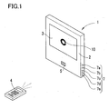
- FIG. 1 is an external view of an optotype presenting apparatus of the present embodiment.
- a color liquid crystal display (LCD) 3 is arranged to present optotypes or charts.
- the display 3 used in the present embodiment is a 19-inch diagonal display in order to display a test optotype 10 of a predetermined size even where the apparatus is located at a far-vision test distance of 5 m, for example.
- a receiving part 5 is provided to receive infrared light communication signals from a remote control 4.
- a switch section 7 is provided including a plurality of switches 7a to 7e which are used for various settings of the apparatus in use.
- the optotype 10 displayed on the display 3 is changed to another by manipulation of the remote control 4. In the case of a visual acuity test optotype of a single character such as the optotype 10, the optotype 10 is displayed in almost the center of the display 3.
- Fig. 2 is a block diagram showing a control system of the optotype presenting apparatus 1.
- a control unit 20 is connected to the display 3, the receiving part 5, and a memory 21 which stores various optotype patterns, luminance adjustment values (the details thereof will be mentioned later), and others.
- the display 3 includes a liquid crystal panel 3a and a backlight 3b for illuminating the liquid crystal panel 3a from behind.
- the control unit 20 controls the backlight 3b to change the background luminance of the optotype 10 displayed on the liquid crystal panel 3a.
- the control unit 20 includes a circuit for controlling voltage for operating the backlight 3b. Further, the control unit 20 internally contains a decoder circuit for decoding command signals from the remote control 4 and others.
- the remote control 4 is provided with a plurality of buttons for operating an apparatus main body and a liquid crystal display 41 which displays the operating condition set with those buttons.
- a visual acuity test optotype selector switches 42 corresponding to a visual acuity When one of visual acuity test optotype selector switches 42 corresponding to a visual acuity is selectively pressed, the optotype corresponding to the visual acuity is displayed on the display 3. Simultaneously, the same optotype appears together with the visual acuity on the display 41.
- Test optotype selector switches 43 are used to display various optotypes or charts for examining visual functions in a red-green test, a cross-cylinder test, a binocular vision test, etc.
- With press of an orientation-changing button 44 With press of an orientation-changing button 44, the orientation of a currently appearing optotype is changed to another one. With press of a visual acuity changing button 45, the visual acuity of the currently appearing opto
- the background luminance of the optotype 10 displayed on the display 3 has to fall within the range permissible for a visual acuity test (hereinafter, referred to as a "standard range").
- This standard range is for example 80 cd/m 2 to 320 cd/m 2 .
- this is a relatively wide permissible range.
- Even within this standard range therefore, if the luminance largely varies among apparatuses, it may cause different visual acuity test results.
- the apparatus of the present embodiment is previously adjusted to have a substantially fixed luminance within a range (e.g., a range of ⁇ 20 cd/m 2 relative to a certain luminance) narrower than the standard range.
- the background luminance of the new apparatus may different from the existing apparatus. If the background luminance of the new apparatus is fixed, the new apparatus could not ensure compatibility with the existing apparatus.
- the apparatus of the present embodiment is therefore provided with a luminance changing function of changing the background luminance of optotypes or charts in two levels or more by changing an adjustment value (standard light intensity changing data) for changing the intensity of the backlight 3b of the display 3.
- the luminance change in the present embodiment is performed in five levels but may be conducted in more than five levels.
- the intensity of the backlight 3b is changed by applied voltage output via a D/A converter and the like of the control unit 20. Specifically, when the voltage to be applied to the backlight 3b is changed in a range of for example 0V to 5V, the luminance becomes highest at 0V and lowest at 5V.
- the luminance adjustment value is expressed by 0 to 255 corresponding to the applied voltage of 0V to 5V divided into 256 scales so that 0V corresponds to an adjustment value "0" and 5V corresponds to an adjustment value "255". Accordingly, the control unit 20 controls to change the intensity of the backlight 3b according to the adjustment value, 0 to 255.
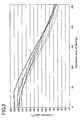
- the luminance varies among the apparatuses even at the same adjustment value.
- the relationship is not partly proportional as viewed as a whole. In a range of 80 to 250 cd/m 2 , however, the luminance of each apparatus changes in an almost proportional relationship with the backlight adjustment value.
- the maximum luminance and the minimum luminance are also different from apparatus to apparatus, but the inclinations of luminance change with respect to adjustment value are similar to one another.
- a rate of change to an adjustment value "10" is averagely about 10 cd/m 2 .
- the minimum luminances are different in a range of 66 to 80 cd/m 2 and most of them are lower than 80 cd/m 2 which is a lower limit of the standard range.
- the maximum luminances are different in a range of 244 to 281 cd/m 2 .
- All of the displays 3 used in the apparatuses did not provide the luminance exceeding 320 cd/m 2 which was an upper limit of the standard range. However, a display providing a luminance of more than 320 cd/m 2 is sufficiently likely to be created by recent improvements in high-luminance LCDs.
- some of the apparatuses may provide the luminance outside the standard range (80 to 320 cd/m 2 ).
- the adjustment values previously set in correspondence to change levels are stored in the memory 21 so that the luminance falls within a predetermined permissible range at each change level without falling outside the standard range permissible for the visual acuity test even when the luminance is changed.
- the adjustment values (correction light intensity changing data) stored in the memory 21 are specific to each apparatus. The following explanation is given to a setting manner of the adjustment value.
- Level 5 is set as the maximum level in the present embodiment. If the luminance of the display 3 is higher, subsequent levels such as Level 6, Level 7, .... may be added in the same way. In this case, the additional levels are defined not to exceed the upper limit of the standard range; 320 cd/m 2 .
- the permissible range ( ⁇ 20 cd/m 2 ) at each level in the present embodiment is set as a range in which the background of optotypes is apparently unchanged. As an alternative, the permissible range at each level may be narrower (e.g. ⁇ 10 cd/m 2 ) for finer change levels.
- the operator increases or decreases the adjustment value with the switch 7a or 7b.
- the intensity of the backlight 3b is changed correspondingly.
- the adjustment value is increased with the switch 7a to lower the luminance. It is experimentally found from the average of many apparatuses that the rate of change is about 10 cd/m 2 in steps of an adjustment value "10" as mentioned above. This may serve as a guide for changing the adjustment value.
- the adjustment value corresponding to the target luminance at Level 4 is determined.
- the adjustment value is set to "75", so that the luminance can be adjusted to about 220 cd/m 2 at Level 4.
- the adjustment value corresponds to the luminance value. Accordingly, the following description mainly mentions increase and decrease in the adjustment value but may be read by replacing it with increase and decrease in the luminance value. This replacement also can embody the above concept.
- the cursor 62 is moved to an adjustment value box 61c for Level 3.
- the adjustment value is changed in a similar manner to the above case to change the intensity of the backlight 3b.
- the luminance of the display 3 is then measured with the luminance meter.
- the adjustment value is set to achieve about a target luminance (180 cd/m 2 ) for Level 3.
- the same manner is applied to Level 2, Level 1, and Level 5 to set respective adjustment values in boxes 61d, 61e, and 61a to achieve about respective target luminances.
- the adjustment values for Levels 1, 2, 3, 4, and 5 are set to for example "225", “175", “125", “75”, and "25” respectively.
- the luminance adjusting mode is canceled and the screen of the display 3 is returned to the test optotype presenting state.
- the initial values stored in the memory 21 are updated to the currently set adjustment values. It is to be noted that the standard luminance during manufacture is set as Level 4.
- an input device or means may be provided to directly input the luminance value measured by the luminance meter.
- it may be configured to compare the background luminance input by the input device or means and the target luminance and automatically calculate a correction adjustment value.
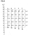
- the luminance adjustment value corresponding to each level is set to be a specific value to each apparatus.
- the adjustment values for Levels 1, 2, 3, 4, and 5 are set to for example "200", “150”, “100”, “50”, and "0" respectively.
- the parenthetic numerals in each bar graph indicating the adjustment range of each apparatus A to E are examples of an adjustment value corresponding to each level.
- the luminances at Levels 1 to 5 can be set without falling outside the standard range in the above manner. However, it takes a lot of time and trouble to measure actual luminance at each level with the luminance meter and then adjust the luminance at each level so as to fall within the predetermined permissible range.
- the following explanation is given to an example of simplifying the adjustment work by executing an automatic luminance adjustment program previously stored in the memory 21.
- the adjustment value setting section 60 is displayed in the lower right part of the display 3 as in Fig. 5 .
- the initial values appear in the adjustment boxes 61a to 61e of the setting section 60.
- the program is configured so that when a certain value "X" is set as the adjustment value for Level 3, the adjustment values at other Levels 1, 2, 4, and 5 are automatically determined by the following calculation.
- the intensity of the backlight 3b is changed based on the initial adjustment value "110" for Level 3.
- the luminance is measured at this time with the luminance meter.
- the adjustment value is changed with the switch 7a or 7b to achieve a luminance of about 180 cd/m 2 which is the center of the permissible range.
- the adjustment values for Levels 1, 2, 4, and 5 are automatically set to "218"(118+100), "168"(118+50), "68"(118-50), and "18"(118-100), respectively.
- the luminance adjusting mode is canceled with simultaneous pressing of the switches 7d and 7e and the adjustment values stored in the memory 21 are updated to the changed adjustment values.
- the adjustment value for any one of Levels 1 to 5 is determined, the adjustment values for remaining levels are automatically set to provide the luminance in each permissible range. Thus, a simplified adjustment work can be achieved.
- the above setting can reduce luminance differences among the apparatuses, thus enabling accurate tests.
- the luminance is different between the existing optotype presenting apparatus used heretofore (e.g. a projecting type optotype presenting apparatus) and the newly adopted apparatus of the present embodiment
- the luminance of the new apparatus is changed to have compatibility in test results with the apparatus used heretofore.
- the switch 7b or 7a is pressed. Specifically, the luminance is changed stepwise up to the luminance at Level 1 with every press of the switch 7b and alternatively changed stepwise up to the luminance at Level 5 with every press of the switch 7a.
- the control unit 20 Upon receipt of a luminance changing signal (a selection signal representing one of Levels 1 to 5) from the switch 7a or 7b, the control unit 20 calls up the adjustment value corresponding to the selected level and controls the voltage to be applied to the backlight 3b based on the adjustment value to change the luminance of the display 3.
- This luminance change to any one of Levels 1 to 5 may be decided by visually comparing the luminance with that of the existing apparatus. Even where the luminance is changed to the minimum luminance, Level 1, the luminance does not fall below 80 cd/m 2 which is the lower limit of the standard range. Even where the luminance is changed to the maximum luminance, Level 5, the luminance does not exceed 320 cd/m 2 which is the upper limit of the standard range. Accordingly, the luminance does not fall outside the standard range, thus enabling appropriate tests.
- the rate of luminance change is nearly proportional to the change of adjustment value used in the luminance adjusting mode in the present embodiment. In some of the optotype presenting apparatuses, however, such almost proportional relationship could not always be provided depending on the characteristic of the backlight 3b of the display 3. It is for example conceivable that the luminance exhibits a parabolic curve with respect to the adjustment value as shown in Fig. 6 .
- the luminances corresponding to initial values L1, L2, L3, L4, and L5 for Levels 1 to 5 may be assumed to be I1, I2, I3, I4, and I5 respectively.
- automatic setting may be adopted to add weight to the rate of change in the adjustment value by considering that the rate of change in each luminance I1 to I5 varies with respect to the change of the adjustment value around each of the initial values L1 to L5 for Levels 1 to 5.
- the automatic setting in the luminance adjusting mode may be appropriately programmed according to the characteristic of the backlight 3b.
- the luminances of the new apparatuses can be adjusted easily to be almost the same by setting the same one of Levels 1 to 5.
- the luminances of the apparatuses in all the stores are adjusted to the same level, the luminance can be easily be changed to almost the same in all the stores, so that the apparatuses have compatibility to enable appropriate tests.
- the changeable range is defined by the standard range (80 to 320 cd/m 2 ) permissible for the visual acuity test optotypes.
- the changeable levels may be increased in addition to at least the changeable levels corresponding to the standard range.
- a warning means is provided for example to cause the display 3 to show a message to inform that the luminance is changed to a level outside the standard range.
- the display 3 is arranged to display the test optotype 10 and, in use for purposes other than tests, display graphics such as digital photographs under control of the control unit 20.
- the display 3 may be used for shop advertisement at any time other than tests.
- the backlight 3b is also turned on for other than tests and thus remains lighted for a long time. Accordingly, the backlight 3b of the display 3 is decreased in light intensity as the lighting time (operation time) is longer.
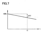
- Fig. 7 is a graph to explain the rate of decrease in light intensity with respect to the lighting time "t" of the backlight 3b.
- the rate of decrease in light intensity to the lighting time is available from a manufacturer of the display 3 and also can be experimentally determined.
- a rate of decrease ⁇ K1 is the rate of decrease corresponding to a luminance decrease of 10 cd/m 2 .
- the lighting time at that time is assumed to be t1.
- An arithmetic expression representing a relationship between this rate of decrease ⁇ K1 and the lighting time t1 is stored in advance in the control unit 20.
- the control unit 20 causes a timer 23 to measure the lighting time of the backlight 3b and, when the measured time reaches t1, the adjustment value corresponding to each level stored in the memory 21 is corrected based on the rate of decrease ⁇ K1.
- the decrease in intensity of the backlight 3b is compensated. This makes it possible to maintain the luminance of the display 3 in a fixed range, thus enabling accurate tests.
- the correction of decreased light intensity of the backlight 3b due to age deterioration may be performed automatically as above or manually. This manual correction is explained below.
- a second luminance adjusting mode is established with press of the switches 7c and 7d, displaying an adjustment screen similar to that in Fig. 5 on the display 3.
- the control unit 20 uniformly changes the adjustment values for other levels by the same rate of change.
- the adjustment values for Level 4 are changed from “60" to "50"
- the adjustment values for other levels are also changed uniformly by the rate of change "-10".
- the second luminance adjusting mode is terminated by pressing the switch 7a or 7b again.
- the adjustment values corresponding to the levels stored in the memory 21 are updated to the changed adjustment values. Accordingly, even the decrease in light intensity due to age deterioration can be supported easily.
Landscapes
- Life Sciences & Earth Sciences (AREA)
- Health & Medical Sciences (AREA)
- Medical Informatics (AREA)
- Biophysics (AREA)
- Ophthalmology & Optometry (AREA)
- Engineering & Computer Science (AREA)
- Biomedical Technology (AREA)
- Heart & Thoracic Surgery (AREA)
- Physics & Mathematics (AREA)
- Molecular Biology (AREA)
- Surgery (AREA)
- Animal Behavior & Ethology (AREA)
- General Health & Medical Sciences (AREA)
- Public Health (AREA)
- Veterinary Medicine (AREA)
- Eye Examination Apparatus (AREA)
- Control Of Indicators Other Than Cathode Ray Tubes (AREA)
- Liquid Crystal Display Device Control (AREA)
Claims (5)
- Sehzeichendarstellvorrichtung (1), die ein Sehzeichen für einen Sehschärfentest darstellt, wobei die Vorrichtung aufweist:eine Anzeige (3), die ein Gegenlicht (3b) enthält, das die Anzeige (3) beleuchtet; undein Lichtintensitätsveränderungsmittel (20) zum Verändern der Lichtintensität des Gegenlichts;ein Hintergrundhelligkeitsauswahlmittel (20) zum Auswählen eines gewissen Niveaus aus einer Vielzahl von verschiedenen Niveaus der Hintergrundhelligkeit des Sehzeichens,wobeiein erlaubter Bereich der Hintergrundhelligkeit, der in dem Sehschärfentest definiert ist, in eine Vielzahl von verschiedenen Bereichen eingeteilt ist, und jedes Niveau der Hintergrundhelligkeit durch einen der Bereiche definiert ist;und wobei bei jedem Niveau in dem Hintergrundhelligkeitsbereich die Helligkeit als nahezu gleich erscheint; undgekennzeichnet durcheinen Speicher (21) zum Speichern eines Einstellwerts des Lichtintensitätsveränderungsmittels entsprechend einer vorbestimmten Hintergrundhelligkeit in dem Hintergrundhelligkeitsbereich bei jedem Niveau; undein Korrekturmittel (3, 7, 20) zum Korrigieren des Einstellwerts, wobei das Korrekturmittel enthält:ein Eingabemittel (7) zum Eingeben der Hintergrundhelligkeit, die von einem Helligkeitsmesser gemessen wird, wobei die gemessene Hintergrundhelligkeit eine Hintergrundhelligkeit ist, die erhalten wird, wenn das Lichtintensitätsveränderungsmittel basierend auf dem Einstellwert bei dem ausgewählten Niveau betrieben wird;ein Berechnungsmittel (20) zum Korrigieren des Einstellwerts bei dem ausgewählten Niveau durch Vergleichen der Hintergrundhelligkeitseingabe durch das Eingabemittel und der vorbestimmten Hintergrundhelligkeit, die dem Einstellwert bei dem ausgewählten Niveau entspricht, undSteuermittel zum Steuern des Lichtintensitätsveränderungsmittels basierend auf dem ausgewählten Niveau und dem korrigierten Einstellwert.
- Sehzeichendarstellvorrichtung gemäß Anspruch 1, wobei das Berechnungsmittel die Einstellwerte bei allen Niveaus, die in dem Speicher gespeichert sind, basierend auf dem korrigierten Einstellwert korrigiert.
- Sehzeichendarstellvorrichtung gemäß Anspruch 1, wobei das Berechnungsmittel des Korrekturmittels die Einstellwerte bei allen Niveaus basierend auf einer Lichtintensitätsveränderungseigenschaft des Gegenlichts korrigiert.
- Sehzeichendarstellvorrichtung gemäß Anspruch 3, wobei das Berechnungsmittel den Einstellwert bei dem ausgewählten Niveau durch den Vergleich korrigiert und die Einstellwerte bei allen Niveaus basierend auf dem korrigierten Einstellwert und der Lichtintensitätsveränderungseigenschaft korrigiert.
- Sehzeichendarstellvorrichtung gemäß einem der Ansprüche 1 bis 4, wobei
das Lichtintensitätsveränderungsmittel einen Schaltkreis zum Verändern einer Spannung enthält, die an das Gegenlicht angelegt wird.
Applications Claiming Priority (1)
| Application Number | Priority Date | Filing Date | Title |
|---|---|---|---|
| JP2007045564A JP5085957B2 (ja) | 2007-02-26 | 2007-02-26 | 視標呈示装置 |
Publications (2)
| Publication Number | Publication Date |
|---|---|
| EP1961373A1 EP1961373A1 (de) | 2008-08-27 |
| EP1961373B1 true EP1961373B1 (de) | 2010-11-24 |
Family
ID=39338651
Family Applications (1)
| Application Number | Title | Priority Date | Filing Date |
|---|---|---|---|
| EP08002537A Not-in-force EP1961373B1 (de) | 2007-02-26 | 2008-02-12 | Vorrichtung zur Darstellung von Optotypen |
Country Status (6)
| Country | Link |
|---|---|
| US (1) | US7549751B2 (de) |
| EP (1) | EP1961373B1 (de) |
| JP (1) | JP5085957B2 (de) |
| KR (1) | KR101464746B1 (de) |
| CN (1) | CN101254089B (de) |
| DE (1) | DE602008003597D1 (de) |
Families Citing this family (19)
| Publication number | Priority date | Publication date | Assignee | Title |
|---|---|---|---|---|
| JP4980780B2 (ja) * | 2007-04-20 | 2012-07-18 | 株式会社ニデック | 視標呈示装置 |
| AU2010247901B2 (en) | 2009-05-09 | 2015-05-21 | Vital Art And Science, Llc | Shape discrimination vision assessment and tracking system |
| JP5907335B2 (ja) * | 2011-10-07 | 2016-04-26 | 株式会社ニデック | 視標呈示装置 |
| KR101245330B1 (ko) * | 2011-12-20 | 2013-03-25 | 경희대학교 산학협력단 | 개인용 컴퓨터 기반 시야 자가진단 시스템 및 시선 고정방법 |
| JP2014018454A (ja) * | 2012-07-19 | 2014-02-03 | Topcon Corp | 視標呈示装置 |
| TWI496119B (zh) * | 2013-02-08 | 2015-08-11 | Wistron Corp | 耗能警示方法與使用該耗能警示方法之顯示器 |
| EP4218543A1 (de) | 2013-04-26 | 2023-08-02 | Genentech, Inc. | Perimetrie-sichttest mit konturenintegration |
| US9833137B1 (en) * | 2014-05-02 | 2017-12-05 | Innova Systems, Inc. | Method and apparatus for administering a low luminance visual dysfunction test |
| US10561312B2 (en) * | 2014-05-02 | 2020-02-18 | Cheryl Nordstrom | Method and apparatus for administering a low luminance visual dysfunction test |
| CN104739363B (zh) | 2015-04-17 | 2017-02-01 | 京东方科技集团股份有限公司 | 一种视力检测方法、装置和系统 |
| US10548473B2 (en) * | 2015-06-23 | 2020-02-04 | Essilor International | Optometry measuring scale |
| CN105919549A (zh) * | 2016-07-08 | 2016-09-07 | 温州星康医学科技有限公司 | 视力表装置、自测视力系统及自测方法 |
| US10016128B2 (en) * | 2016-09-27 | 2018-07-10 | David Evans | Method and apparatus for vision acuity testing |
| US10022045B1 (en) * | 2017-02-28 | 2018-07-17 | David Evans | Method and apparatus for vision acuity testing |
| US10413172B2 (en) * | 2017-12-11 | 2019-09-17 | 1-800 Contacts, Inc. | Digital visual acuity eye examination for remote physician assessment |
| DE102018215307A1 (de) * | 2018-09-10 | 2020-03-12 | Carl Zeiss Meditec Ag | Verfahren zur Steuerung der Beleuchtung ophthalmologischer Geräte |
| JP7252023B2 (ja) * | 2019-03-22 | 2023-04-04 | ソニー・オリンパスメディカルソリューションズ株式会社 | 画像処理装置及び医療用観察システム |
| JP7635665B2 (ja) * | 2021-07-20 | 2025-02-26 | 株式会社ニデック | 視標呈示装置及び視標呈示プログラム |
| JP7635664B2 (ja) * | 2021-07-20 | 2025-02-26 | 株式会社ニデック | 視標呈示装置及び視標呈示プログラム |
Family Cites Families (14)
| Publication number | Priority date | Publication date | Assignee | Title |
|---|---|---|---|---|
| US5078486A (en) * | 1989-10-13 | 1992-01-07 | Evans David W | Self-calibrating vision test apparatus |
| US5568209A (en) | 1995-04-17 | 1996-10-22 | Priester; William B. | Automated pocket-sized near vision tester |
| JPH0994222A (ja) * | 1995-09-29 | 1997-04-08 | Nidek Co Ltd | 視力検査装置 |
| US5880814A (en) | 1996-10-30 | 1999-03-09 | Mentor Corporation | Visual acuity tester with improved test character generation |
| US5929972A (en) * | 1998-01-14 | 1999-07-27 | Quo Vadis, Inc. | Communication apparatus and method for performing vision testing on deaf and severely hearing-impaired individuals |
| US6425665B2 (en) | 2000-03-31 | 2002-07-30 | Nidek Co., Ltd. | Visual acuity examination apparatus |
| JP3850254B2 (ja) * | 2000-10-20 | 2006-11-29 | 株式会社ニデック | 省スペース型視機能検査装置 |
| WO2002076301A1 (en) | 2001-03-21 | 2002-10-03 | Marino Joseph A | Apparatus and method for testing visual acuity and fixation control |
| JP3958958B2 (ja) * | 2001-11-30 | 2007-08-15 | 興和株式会社 | 電子機器 |
| JP3953877B2 (ja) * | 2002-04-19 | 2007-08-08 | 株式会社ニデック | 視力検査装置 |
| JP3697612B2 (ja) * | 2002-05-15 | 2005-09-21 | 株式会社日本点眼薬研究所 | 近距離視力検査具 |
| JP2006014766A (ja) * | 2004-06-30 | 2006-01-19 | Nidek Co Ltd | 視機能検査装置 |
| JP2006042978A (ja) | 2004-08-02 | 2006-02-16 | Nidek Co Ltd | 検眼装置 |
| JP2006198286A (ja) * | 2005-01-24 | 2006-08-03 | Topcon Corp | 視力表装置及び検眼装置 |
-
2007
- 2007-02-26 JP JP2007045564A patent/JP5085957B2/ja not_active Expired - Fee Related
-
2008
- 2008-01-31 US US12/010,975 patent/US7549751B2/en active Active
- 2008-02-12 EP EP08002537A patent/EP1961373B1/de not_active Not-in-force
- 2008-02-12 DE DE602008003597T patent/DE602008003597D1/de active Active
- 2008-02-25 CN CN2008100811241A patent/CN101254089B/zh not_active Expired - Fee Related
- 2008-02-26 KR KR1020080017283A patent/KR101464746B1/ko not_active Expired - Fee Related
Also Published As
| Publication number | Publication date |
|---|---|
| CN101254089B (zh) | 2011-11-16 |
| EP1961373A1 (de) | 2008-08-27 |
| US20080204662A1 (en) | 2008-08-28 |
| JP5085957B2 (ja) | 2012-11-28 |
| DE602008003597D1 (de) | 2011-01-05 |
| KR20080079223A (ko) | 2008-08-29 |
| US7549751B2 (en) | 2009-06-23 |
| JP2008206675A (ja) | 2008-09-11 |
| KR101464746B1 (ko) | 2014-11-24 |
| CN101254089A (zh) | 2008-09-03 |
Similar Documents
| Publication | Publication Date | Title |
|---|---|---|
| EP1961373B1 (de) | Vorrichtung zur Darstellung von Optotypen | |
| US8087781B2 (en) | Optotype presenting apparatus | |
| JP5555252B2 (ja) | 視覚刺激のための高精度コントラスト比ディスプレイ装置及び方法 | |
| EP1878378B1 (de) | Vorrichtung zur Darstellung von Optotypen | |
| US20080143961A1 (en) | Apparatus and method for testing visual acuity and fixation control | |
| US8444270B2 (en) | Auto-phoropter interface and computer monitor filter | |
| JP7157070B2 (ja) | 視力検査の方法及び装置 | |
| JP5749511B2 (ja) | 検眼システム | |
| JP2008284264A (ja) | 検眼装置 | |
| JP7039602B2 (ja) | 視力試験用の方法及び装置 | |
| JP2002200041A (ja) | 検眼装置 | |
| EP1386577B1 (de) | Optometrisches Instrument | |
| JP2013081593A (ja) | 視標呈示装置 | |
| JP7624352B2 (ja) | 視標提示装置 | |
| JP2824788B2 (ja) | 静的視野測定装置 | |
| KR20220140340A (ko) | 영상시력측정 기능을 갖는 복합 검안기 |
Legal Events
| Date | Code | Title | Description |
|---|---|---|---|
| PUAI | Public reference made under article 153(3) epc to a published international application that has entered the european phase |
Free format text: ORIGINAL CODE: 0009012 |
|
| AK | Designated contracting states |
Kind code of ref document: A1 Designated state(s): AT BE BG CH CY CZ DE DK EE ES FI FR GB GR HR HU IE IS IT LI LT LU LV MC MT NL NO PL PT RO SE SI SK TR |
|
| AX | Request for extension of the european patent |
Extension state: AL BA MK RS |
|
| 17P | Request for examination filed |
Effective date: 20090226 |
|
| AKX | Designation fees paid |
Designated state(s): DE FR GB |
|
| 17Q | First examination report despatched |
Effective date: 20090508 |
|
| GRAP | Despatch of communication of intention to grant a patent |
Free format text: ORIGINAL CODE: EPIDOSNIGR1 |
|
| GRAS | Grant fee paid |
Free format text: ORIGINAL CODE: EPIDOSNIGR3 |
|
| GRAA | (expected) grant |
Free format text: ORIGINAL CODE: 0009210 |
|
| AK | Designated contracting states |
Kind code of ref document: B1 Designated state(s): DE FR GB |
|
| REG | Reference to a national code |
Ref country code: GB Ref legal event code: FG4D |
|
| REF | Corresponds to: |
Ref document number: 602008003597 Country of ref document: DE Date of ref document: 20110105 Kind code of ref document: P |
|
| PLBE | No opposition filed within time limit |
Free format text: ORIGINAL CODE: 0009261 |
|
| STAA | Information on the status of an ep patent application or granted ep patent |
Free format text: STATUS: NO OPPOSITION FILED WITHIN TIME LIMIT |
|
| 26N | No opposition filed |
Effective date: 20110825 |
|
| REG | Reference to a national code |
Ref country code: DE Ref legal event code: R097 Ref document number: 602008003597 Country of ref document: DE Effective date: 20110825 |
|
| PGFP | Annual fee paid to national office [announced via postgrant information from national office to epo] |
Ref country code: FR Payment date: 20120221 Year of fee payment: 5 |
|
| PGFP | Annual fee paid to national office [announced via postgrant information from national office to epo] |
Ref country code: DE Payment date: 20120208 Year of fee payment: 5 |
|
| PGFP | Annual fee paid to national office [announced via postgrant information from national office to epo] |
Ref country code: GB Payment date: 20120208 Year of fee payment: 5 |
|
| GBPC | Gb: european patent ceased through non-payment of renewal fee |
Effective date: 20130212 |
|
| REG | Reference to a national code |
Ref country code: FR Ref legal event code: ST Effective date: 20131031 |
|
| REG | Reference to a national code |
Ref country code: DE Ref legal event code: R119 Ref document number: 602008003597 Country of ref document: DE Effective date: 20130903 |
|
| PG25 | Lapsed in a contracting state [announced via postgrant information from national office to epo] |
Ref country code: FR Free format text: LAPSE BECAUSE OF NON-PAYMENT OF DUE FEES Effective date: 20130228 Ref country code: DE Free format text: LAPSE BECAUSE OF NON-PAYMENT OF DUE FEES Effective date: 20130903 Ref country code: GB Free format text: LAPSE BECAUSE OF NON-PAYMENT OF DUE FEES Effective date: 20130212 |