EP1961437B1 - Instruments pour injections dont l'aiguille peut se rétracter après utilisation - Google Patents
Instruments pour injections dont l'aiguille peut se rétracter après utilisation Download PDFInfo
- Publication number
- EP1961437B1 EP1961437B1 EP08425090A EP08425090A EP1961437B1 EP 1961437 B1 EP1961437 B1 EP 1961437B1 EP 08425090 A EP08425090 A EP 08425090A EP 08425090 A EP08425090 A EP 08425090A EP 1961437 B1 EP1961437 B1 EP 1961437B1
- Authority
- EP
- European Patent Office
- Prior art keywords
- needle
- connecting element
- holder block
- neck
- instrument
- Prior art date
- Legal status (The legal status is an assumption and is not a legal conclusion. Google has not performed a legal analysis and makes no representation as to the accuracy of the status listed.)
- Not-in-force
Links
- 238000002347 injection Methods 0.000 title claims abstract description 25
- 239000007924 injection Substances 0.000 title claims abstract description 25
- 239000012907 medicinal substance Substances 0.000 claims abstract description 12
- 230000001681 protective effect Effects 0.000 claims description 6
- 239000003708 ampul Substances 0.000 claims description 4
- 230000000903 blocking effect Effects 0.000 claims description 4
- 239000000463 material Substances 0.000 claims description 3
- 238000000465 moulding Methods 0.000 claims description 2
- 208000027418 Wounds and injury Diseases 0.000 claims 1
- 230000006378 damage Effects 0.000 claims 1
- 208000015181 infectious disease Diseases 0.000 claims 1
- 208000014674 injury Diseases 0.000 claims 1
- 238000004891 communication Methods 0.000 description 2
- 238000011109 contamination Methods 0.000 description 2
- 239000012530 fluid Substances 0.000 description 2
- 239000000243 solution Substances 0.000 description 2
- 238000001802 infusion Methods 0.000 description 1
- 239000007927 intramuscular injection Substances 0.000 description 1
- 238000010255 intramuscular injection Methods 0.000 description 1
- 239000007788 liquid Substances 0.000 description 1
- 238000000034 method Methods 0.000 description 1
- 230000007935 neutral effect Effects 0.000 description 1
- 230000010355 oscillation Effects 0.000 description 1
- 239000007929 subcutaneous injection Substances 0.000 description 1
- 238000010254 subcutaneous injection Methods 0.000 description 1
- 239000000126 substance Substances 0.000 description 1
Images


Classifications
-
- A—HUMAN NECESSITIES
- A61—MEDICAL OR VETERINARY SCIENCE; HYGIENE
- A61M—DEVICES FOR INTRODUCING MEDIA INTO, OR ONTO, THE BODY; DEVICES FOR TRANSDUCING BODY MEDIA OR FOR TAKING MEDIA FROM THE BODY; DEVICES FOR PRODUCING OR ENDING SLEEP OR STUPOR
- A61M5/00—Devices for bringing media into the body in a subcutaneous, intra-vascular or intramuscular way; Accessories therefor, e.g. filling or cleaning devices, arm-rests
- A61M5/178—Syringes
- A61M5/31—Details
- A61M5/32—Needles; Details of needles pertaining to their connection with syringe or hub; Accessories for bringing the needle into, or holding the needle on, the body; Devices for protection of needles
- A61M5/3205—Apparatus for removing or disposing of used needles or syringes, e.g. containers; Means for protection against accidental injuries from used needles
- A61M5/321—Means for protection against accidental injuries by used needles
- A61M5/322—Retractable needles, i.e. disconnected from and withdrawn into the syringe barrel by the piston
- A61M5/3232—Semi-automatic needle retraction, i.e. in which triggering of the needle retraction requires a deliberate action by the user, e.g. manual release of spring-biased retraction means
-
- A—HUMAN NECESSITIES
- A61—MEDICAL OR VETERINARY SCIENCE; HYGIENE
- A61M—DEVICES FOR INTRODUCING MEDIA INTO, OR ONTO, THE BODY; DEVICES FOR TRANSDUCING BODY MEDIA OR FOR TAKING MEDIA FROM THE BODY; DEVICES FOR PRODUCING OR ENDING SLEEP OR STUPOR
- A61M5/00—Devices for bringing media into the body in a subcutaneous, intra-vascular or intramuscular way; Accessories therefor, e.g. filling or cleaning devices, arm-rests
- A61M5/178—Syringes
- A61M5/28—Syringe ampoules or carpules, i.e. ampoules or carpules provided with a needle
- A61M5/281—Syringe ampoules or carpules, i.e. ampoules or carpules provided with a needle using emptying means to expel or eject media, e.g. pistons, deformation of the ampoule, or telescoping of the ampoule
- A61M5/282—Syringe ampoules or carpules, i.e. ampoules or carpules provided with a needle using emptying means to expel or eject media, e.g. pistons, deformation of the ampoule, or telescoping of the ampoule by compression of deformable ampoule or carpule wall
Definitions
- This invention concerns the medical field and refers in particular to an instrument for intramuscular and subcutaneous injections of the type comprised of a ampoule or phial of medicinal substances connected to a needle for injections.
- an instrument for injections that comprises a container shaped as an ampoule or phial, of a flexible material, preloaded or loadable, and a needle for injections supported by a connecting element is already known.
- the medicinal container has a neck and the needle is coupled to said neck either by being screwed or pressed into it.
- the neck of the container is sealed, but it may be perforated; the needle has a rear perforating end facing towards the neck; the connecting element is constrained in a first position relatively to the neck of the container so that the rear perforating end of the needle is at a distance from the neck so as not to perforate it; the needle is enclosed in a protective cap.
- the connecting element is tightly engaged on the neck of the container in a second position so that the perforating end of the needle will perforate the neck and thus be in communication with the inside of the container.
- the injection can be executed by compressing the container obliging the medicinal substance to exit from the needle towards the patient.
- the needle remains in a fixed position and exposed with the risk of injuring/contaminating anybody accidentally coming into contact with it, even only when replacing the protective cap.
- a unit dose syringe comprises a fluid-containing plastic bag with an attached needle and a dimensionally-stable shell like a woman's compact.
- the shell contains a thumb-operated slider assembly for advancing the needle to an exposed position for fluid delivery.
- the syringe also includes a spring-biasing arrangement to return the needle, automatically, to the protected position, after use, and a means for rupturing the bag and retaining the needle in the protected position.
- the patent application EP 1410818 relates to a vial for injection comprising: an elastically deformable container wherein a solution for injection is hermetically contained, and a male connector protruding forward from said container to engage in a female connector of a needle-carrier which bears a needle.
- the needle has a first tip which protrudes forward from the needle-carrier to engage in the patient's body and a second tip disposed in the female connector of the needle-carrier to perforate the end of said male connector of the vial so that, by means of manual pressure on the container of the vial, the solution contained therein can be injected through the needle into the patient's body.
- the patent application GB 1217152 relates to a syringe, eye-dropper or the like, in which a cannula is forced into a sealed flexible container to deliver or collect a liquid therein, comprises (a flexible container having a plug at one end carrying an external screw thread, on to which fits the internal screw thread of the member carrying the needle. A cover fits over the needle and carrying member and abuts against a shoulder at the base of the container.
- the cover is a friction fit on a part of the member having longitudinal serrations, but both the cover and the members are slightly tapered and/or the cover includes a wider section so that, when the cover is rotated, the needle-carrying member moves inwardly along the screw thread towards the container until the needle pierces the plug, by which time the cover and member have disengaged and the cover can be removed.
- the object of this invention is to remedy this shortcoming and, therefore, create the conditions to protect against any contact and risk of contamination those instruments for injections that use a compressible, preloaded or loadable container with a medicinal substance, connected to a needle for injections moving between a first neutral position and a second perforating position of the container.
- a container of medicinal substance according to the preface of claim 1, wherein the needle is fixed using a needle-holder block provided in the connection element and moving between a forward position in which the needle extends forward beyond the connecting element and a retracted position in which the needle is fully retracted inside the connecting element, and wherein the forward position of the needle-holder block is set by a catch moving between an engaging and a release position of said needle-holder block with said block and the retracted position is originated by a return spring in response to the release of said needle-holder block by the catch.
- the container can be produced both complete with medicinal substance, or empty, to be loaded later by the end operator: by compressing the body of the container to make the air it contains exit and by taking advantage of the consequent return to fill it with medicinal substance.
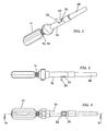
- the instrument for injections comprises a container 11 made of a flexible material in the shape of a compressible ampoule or phial and a needle for injections 12 associated with it.
- the container 11 is filled with an injectable medicinal substance and has a neck 13 that is sealed and has a threaded external section 14.
- the needle 12 is attached to the neck 13 of the container by means of a connecting device 15 with a perforated distal part 16 and a proximal part 17 that is threaded and connects by screwing into the threaded section 14 of said neck.
- the needle 12 has a front end 12' facing towards the distal end 16 of the connecting element and a rear end 12" facing towards the neck 13 of the container 11.
- the connecting element 15 internally forms an axial housing 18, and the needle 12 is fixed to a needle-holder block 19, that is housed inside with the possibility of sliding in the housing 18 of said connecting element 15.
- the needle-holder block 19, including the needle 12, are able to move in said housing 18 between a forward position towards the distal end 16 and a retracted position towards the proximal part 17 of the connecting element 15.
- the needle-holder block 19 and the return spring can be both simply associated individual components, and elements preventively constrained to each other, for example by co-moulding of the needle-holder block 19, needle 12 and spring 20.
- the needle-holder block 19 when the needle-holder block 19 is in the forward position the needle 12 protrudes from the perforated distal end 16 of the connecting element 15. In this position, the return spring 20 is compressed between the needle-holder block 19 and the distal part 16 of the connecting element, and the needle-holder block 19 is held in position by means of a catch 21, positioned at level with the opening 22 in one side of the connecting element 15 and movable between an active blocking position and an inactive release position of the needle-holder block.
- the catch 21 is part of a lever 23 that can be integrally machined with the connecting element 15 and connected with the latter by means of an oscillation fulcrum 24. Furthermore, the catch 21 can be devised so that when it is in the active blocking position it engages with the rear of the needle-holder block 19 as shown in the drawings, or alternatively with an intermediate part of said recess, not shown.
- the lever 23 normally remains in a state in which the catch 21 is in the active blocking position of the needle-holder block 19, but can be manually moved out of said position by means of a grip 25 it is an integral part of, so as to move the catch 21 away from the needle-holder block 19 and thus release the latter so it can move backward towards the proximal end 17 of the connecting element 15.
- the container 11 is filled with a medicinal substance and its neck 13 is sealed.
- the needle-holder block 19 is held in its forward position with the needle protruding from the distal part 16 of the connecting element 15.
- This connecting element 15 is screwed to the container, but only partially until the rear end 12" of the needle reaches the neck 13.
- the portion of the needle 12 that protrudes from the connecting element 15 is subsequently enclosed in a protective cap 26 - Figs-4-6.
- the connecting element 15 When administering the medicinal substance to a patient the connecting element 15 is screwed tightly onto the neck 13 of the container 11 so that the rear end 12" of the needle 12 will perforate the neck. In this way the needle is now in communication with the inside of the container 11 and after removing the protective cap 26, front end 12' of the needle can be inserted into the body of the patient to inject the medicinal substance.
- the operator can use the lever 23 to move the catch 21 away from the needle-holder block 19 and release the latter. Consequently, driven by the return spring 20, the needle-holder block 19 moves back towards the neck 13 of the container until the needle is completely inside the connecting element - Fig. 7 - and therefore in a protected condition without the risk of contact with its front end.
Landscapes
- Health & Medical Sciences (AREA)
- Engineering & Computer Science (AREA)
- Heart & Thoracic Surgery (AREA)
- Vascular Medicine (AREA)
- Anesthesiology (AREA)
- Biomedical Technology (AREA)
- Environmental & Geological Engineering (AREA)
- Hematology (AREA)
- Life Sciences & Earth Sciences (AREA)
- Animal Behavior & Ethology (AREA)
- General Health & Medical Sciences (AREA)
- Public Health (AREA)
- Veterinary Medicine (AREA)
- Infusion, Injection, And Reservoir Apparatuses (AREA)
Claims (7)
- Instrument pour injections avec une aiguille rétractable après utilisation, comprenant un récipient pour un médicament sous forme d'ampoule ou de fiole d'un matériau flexible, et une aiguille pour injections portée par un élément de raccord, où :- ledit récipient a un col scellé avec filetage externe et l'aiguille est couplée par vissage audit col à travers l'élément de raccord ;- l'aiguille a une extrémité antérieure destinée à dépasser vers l'avant de l'élément de raccord et une extrémité postérieure vers le col dudit récipient;- à l'origine, l'élément de raccord n'est que partiellement vissé au col de sorte que l'extrémité postérieure de l'aiguille soit distante dudit col ; et ledit élément de raccord est vissé à fond sur le col du récipient de sorte que l'extrémité postérieure de l'aiguille le perfore au moment d'utiliser l'instrument pour une injection,- l'aiguille (12) est fixée à un bloc porte-aiguille (19) disposé dans ledit élément de raccord (15) et mobile entre une position avancée dans laquelle l'aiguille s'étire vers l'avant au-delà de l'élément de raccord et une position rétractée dans laquelle l'aiguille est complètement retirée à l'intérieur du raccord, la position avancée du bloc porte-aiguille étant définie par un cran (21) mobile entre une position d'interception et une position de libération dudit bloc porte-aiguille (19), tandis que la position rétractée dudit bloc porte-aiguille est causée par un ressort de rappel (20) en réponse à la libération du bloc porte-aiguille par le cran (21),caractérisé en ce que ledit élément de raccord (15) a une extrémité distale percée (16) et une extrémité proximale filetée qui s'unit au col du contenant, dans lequel le bloc porte-aiguille (19) est disposé et coulisse dans ledit siège (18) entre lesdites extrémités proximale et distale, et en ce que le ressort de rappel (20) est disposé et chargé entre le bloc porte-aiguille et l'extrémité distale de l'élément de raccord lorsque le bloc est retenu dans la position avancée.
- Instrument pour injections selon la revendication 1, dans lequel le cran (21) du bloc porte-aiguille (19) fait partie d'un levier (23) relié à l'élément de raccord (15) à travers un centre d'oscillation (24) et ayant une ailette de prise (25) de manière à déplacer le cran de la position d'interception à la position de libération du bloc porte-aiguille.
- Instrument pour injections selon la revendication 3, dans lequel le cran (21) est placé au niveau d'une ouverture (22) dans un côté de l'élément de raccord (15) et s'engage avec l'arrière du bloc porte-aiguille (19) pour retenir ce dernier dans la position avancée.
- Instrument pour injections selon la revendication 2, dans lequel le cran (21) est placé au niveau d'une ouverture (22) dans un côté de l'élément de raccord (15) et s'engage avec une partie intermédiaire du bloc porte-aiguille (19).
- Instrument pour injections selon une quelconque des revendications précédentes, dans lequel le bloc porte-aiguille (19) et le ressort de rappel (20) sont des éléments individuels associés.
- Instrument pour injections selon une quelconque des revendications 1-4, dans lequel le bloc porte-aiguille (19) et le ressort de rappel (20) sont pré-assemblés par surmoulage dudit bloc sur une extrémité dudit ressort.
- Système de sécurité pour empêcher la réutilisation d'une aiguille pour injections afin d'éviter les blessures et/ou la contagion de quiconque qui entre en contact avec celle-ci après utilisation, applicable à des ampoules ou des seringues et incluant un élément de raccord avec aiguille, bloc porte-aiguille, ressort de rappel, système de verrouillage/déverrouillage d'aiguille et capuchon de protection selon une quelconque des revendications précédentes.
Applications Claiming Priority (1)
| Application Number | Priority Date | Filing Date | Title |
|---|---|---|---|
| IT000024A ITBS20070024A1 (it) | 2007-02-26 | 2007-02-26 | Strumento per iniezioni con ago retraibile dopo l'uso |
Publications (2)
| Publication Number | Publication Date |
|---|---|
| EP1961437A1 EP1961437A1 (fr) | 2008-08-27 |
| EP1961437B1 true EP1961437B1 (fr) | 2011-10-26 |
Family
ID=39313483
Family Applications (1)
| Application Number | Title | Priority Date | Filing Date |
|---|---|---|---|
| EP08425090A Not-in-force EP1961437B1 (fr) | 2007-02-26 | 2008-02-14 | Instruments pour injections dont l'aiguille peut se rétracter après utilisation |
Country Status (4)
| Country | Link |
|---|---|
| US (1) | US20080208120A1 (fr) |
| EP (1) | EP1961437B1 (fr) |
| AT (1) | ATE530214T1 (fr) |
| IT (1) | ITBS20070024A1 (fr) |
Families Citing this family (4)
| Publication number | Priority date | Publication date | Assignee | Title |
|---|---|---|---|---|
| USD640787S1 (en) | 2009-07-15 | 2011-06-28 | Becton, Dickinson And Company | Injection device with sealed luer fitting |
| CN102481412B (zh) * | 2009-07-15 | 2016-10-19 | 贝克顿·迪金森公司 | 具有密封鲁尔接头的注射装置 |
| US20130018326A1 (en) * | 2010-04-01 | 2013-01-17 | Enable Injections, Llc | Medical fluid injection device and system |
| WO2013162637A1 (fr) * | 2012-04-25 | 2013-10-31 | Adar Medtech, Inc. | Dispositif d'injection médical prérempli |
Family Cites Families (6)
| Publication number | Priority date | Publication date | Assignee | Title |
|---|---|---|---|---|
| US1236426A (en) * | 1912-06-24 | 1917-08-14 | Greeley Lab Inc | Hypodermic syringe. |
| GB1217152A (en) | 1967-03-14 | 1970-12-31 | Arthur Bane | Improvements in appliances for storing and dispensing fluids, such as hypodermic syringes and eye drop dispensers |
| ES2092572T3 (es) * | 1990-07-04 | 1996-12-01 | Maxwell Edmund Whisson | Dispositivo parenteral mejorado. |
| US5248303A (en) | 1991-08-27 | 1993-09-28 | Margolin George D | Medical syringe with needle-retracting mechanism |
| US5755709A (en) * | 1996-04-25 | 1998-05-26 | Cuppy; Michael J. | Catheter system for percutaneously introducing a liquid |
| EP1410818A1 (fr) | 2002-10-14 | 2004-04-21 | Sergio Restelli | Fiole pour injection avec dispositif de sécurité |
-
2007
- 2007-02-26 IT IT000024A patent/ITBS20070024A1/it unknown
-
2008
- 2008-02-14 EP EP08425090A patent/EP1961437B1/fr not_active Not-in-force
- 2008-02-14 AT AT08425090T patent/ATE530214T1/de not_active IP Right Cessation
- 2008-02-22 US US12/035,730 patent/US20080208120A1/en not_active Abandoned
Also Published As
| Publication number | Publication date |
|---|---|
| US20080208120A1 (en) | 2008-08-28 |
| ATE530214T1 (de) | 2011-11-15 |
| ITBS20070024A1 (it) | 2008-08-27 |
| EP1961437A1 (fr) | 2008-08-27 |
Similar Documents
| Publication | Publication Date | Title |
|---|---|---|
| EP2114495B1 (fr) | Système de garde de sécurité pour une seringue souple fonctionnant par compression à usage unique, et dispositif d'injection | |
| US6039713A (en) | Pre-filled retractable needle injection device | |
| US4553962A (en) | Medical syringe | |
| US5358491A (en) | Cartridge-needle unit having retractable needle | |
| CN103167887B (zh) | 医用注射装置 | |
| US7566324B2 (en) | Injection device comprising a needle cover | |
| CN105592876B (zh) | 安全针设备 | |
| EP3068472B1 (fr) | Dispositif d'accès | |
| EP2542282B1 (fr) | Dispositif d'injection | |
| KR102751238B1 (ko) | 의료용 주입기용 캡 | |
| US20050277896A1 (en) | Device for securing injection needles | |
| US7815610B2 (en) | Injection apparatus | |
| EP4376921B1 (fr) | Système de seringue | |
| CN109982733B (zh) | 一种基于保护壳体的植入物/药剂注射系统 | |
| SK1012002A3 (en) | Device for automatically injecting injection liquids | |
| US5634909A (en) | Auto-retracting needle injector system | |
| CN103889484A (zh) | 注射装置 | |
| CN105744978A (zh) | 注射器装置 | |
| JP4554577B2 (ja) | 針を注射装置に装着するための心合わせ補助具 | |
| EP1961437B1 (fr) | Instruments pour injections dont l'aiguille peut se rétracter après utilisation | |
| AU2004267899B2 (en) | System for administering an injectable product | |
| US20170014579A1 (en) | Blunt cannula needle device | |
| US20240390587A1 (en) | Device for drug injection | |
| EA044677B1 (ru) | Устройство для введения, предназначенное для интравитреального введения жидкости | |
| US20070262167A1 (en) | Disposable syringe |
Legal Events
| Date | Code | Title | Description |
|---|---|---|---|
| PUAI | Public reference made under article 153(3) epc to a published international application that has entered the european phase |
Free format text: ORIGINAL CODE: 0009012 |
|
| AK | Designated contracting states |
Kind code of ref document: A1 Designated state(s): AT BE BG CH CY CZ DE DK EE ES FI FR GB GR HR HU IE IS IT LI LT LU LV MC MT NL NO PL PT RO SE SI SK TR |
|
| AX | Request for extension of the european patent |
Extension state: AL BA MK RS |
|
| 17P | Request for examination filed |
Effective date: 20090129 |
|
| 17Q | First examination report despatched |
Effective date: 20090306 |
|
| AKX | Designation fees paid |
Designated state(s): AT BE BG CH CY CZ DE DK EE ES FI FR GB GR HR HU IE IS IT LI LT LU LV MC MT NL NO PL PT RO SE SI SK TR |
|
| GRAP | Despatch of communication of intention to grant a patent |
Free format text: ORIGINAL CODE: EPIDOSNIGR1 |
|
| GRAS | Grant fee paid |
Free format text: ORIGINAL CODE: EPIDOSNIGR3 |
|
| GRAA | (expected) grant |
Free format text: ORIGINAL CODE: 0009210 |
|
| AK | Designated contracting states |
Kind code of ref document: B1 Designated state(s): AT BE BG CH CY CZ DE DK EE ES FI FR GB GR HR HU IE IS IT LI LT LU LV MC MT NL NO PL PT RO SE SI SK TR |
|
| REG | Reference to a national code |
Ref country code: GB Ref legal event code: FG4D |
|
| REG | Reference to a national code |
Ref country code: CH Ref legal event code: EP |
|
| REG | Reference to a national code |
Ref country code: IE Ref legal event code: FG4D |
|
| REG | Reference to a national code |
Ref country code: DE Ref legal event code: R096 Ref document number: 602008010820 Country of ref document: DE Effective date: 20120119 |
|
| REG | Reference to a national code |
Ref country code: NL Ref legal event code: VDEP Effective date: 20111026 |
|
| LTIE | Lt: invalidation of european patent or patent extension |
Effective date: 20111026 |
|
| REG | Reference to a national code |
Ref country code: AT Ref legal event code: MK05 Ref document number: 530214 Country of ref document: AT Kind code of ref document: T Effective date: 20111026 |
|
| PG25 | Lapsed in a contracting state [announced via postgrant information from national office to epo] |
Ref country code: LT Free format text: LAPSE BECAUSE OF FAILURE TO SUBMIT A TRANSLATION OF THE DESCRIPTION OR TO PAY THE FEE WITHIN THE PRESCRIBED TIME-LIMIT Effective date: 20111026 Ref country code: BE Free format text: LAPSE BECAUSE OF FAILURE TO SUBMIT A TRANSLATION OF THE DESCRIPTION OR TO PAY THE FEE WITHIN THE PRESCRIBED TIME-LIMIT Effective date: 20111026 Ref country code: NO Free format text: LAPSE BECAUSE OF FAILURE TO SUBMIT A TRANSLATION OF THE DESCRIPTION OR TO PAY THE FEE WITHIN THE PRESCRIBED TIME-LIMIT Effective date: 20120126 Ref country code: IS Free format text: LAPSE BECAUSE OF FAILURE TO SUBMIT A TRANSLATION OF THE DESCRIPTION OR TO PAY THE FEE WITHIN THE PRESCRIBED TIME-LIMIT Effective date: 20120226 |
|
| PG25 | Lapsed in a contracting state [announced via postgrant information from national office to epo] |
Ref country code: HR Free format text: LAPSE BECAUSE OF FAILURE TO SUBMIT A TRANSLATION OF THE DESCRIPTION OR TO PAY THE FEE WITHIN THE PRESCRIBED TIME-LIMIT Effective date: 20111026 Ref country code: SE Free format text: LAPSE BECAUSE OF FAILURE TO SUBMIT A TRANSLATION OF THE DESCRIPTION OR TO PAY THE FEE WITHIN THE PRESCRIBED TIME-LIMIT Effective date: 20111026 Ref country code: SI Free format text: LAPSE BECAUSE OF FAILURE TO SUBMIT A TRANSLATION OF THE DESCRIPTION OR TO PAY THE FEE WITHIN THE PRESCRIBED TIME-LIMIT Effective date: 20111026 Ref country code: LV Free format text: LAPSE BECAUSE OF FAILURE TO SUBMIT A TRANSLATION OF THE DESCRIPTION OR TO PAY THE FEE WITHIN THE PRESCRIBED TIME-LIMIT Effective date: 20111026 Ref country code: GR Free format text: LAPSE BECAUSE OF FAILURE TO SUBMIT A TRANSLATION OF THE DESCRIPTION OR TO PAY THE FEE WITHIN THE PRESCRIBED TIME-LIMIT Effective date: 20120127 Ref country code: NL Free format text: LAPSE BECAUSE OF FAILURE TO SUBMIT A TRANSLATION OF THE DESCRIPTION OR TO PAY THE FEE WITHIN THE PRESCRIBED TIME-LIMIT Effective date: 20111026 Ref country code: PL Free format text: LAPSE BECAUSE OF FAILURE TO SUBMIT A TRANSLATION OF THE DESCRIPTION OR TO PAY THE FEE WITHIN THE PRESCRIBED TIME-LIMIT Effective date: 20111026 Ref country code: PT Free format text: LAPSE BECAUSE OF FAILURE TO SUBMIT A TRANSLATION OF THE DESCRIPTION OR TO PAY THE FEE WITHIN THE PRESCRIBED TIME-LIMIT Effective date: 20120227 |
|
| PG25 | Lapsed in a contracting state [announced via postgrant information from national office to epo] |
Ref country code: CY Free format text: LAPSE BECAUSE OF FAILURE TO SUBMIT A TRANSLATION OF THE DESCRIPTION OR TO PAY THE FEE WITHIN THE PRESCRIBED TIME-LIMIT Effective date: 20111026 |
|
| PG25 | Lapsed in a contracting state [announced via postgrant information from national office to epo] |
Ref country code: BG Free format text: LAPSE BECAUSE OF FAILURE TO SUBMIT A TRANSLATION OF THE DESCRIPTION OR TO PAY THE FEE WITHIN THE PRESCRIBED TIME-LIMIT Effective date: 20120126 Ref country code: SK Free format text: LAPSE BECAUSE OF FAILURE TO SUBMIT A TRANSLATION OF THE DESCRIPTION OR TO PAY THE FEE WITHIN THE PRESCRIBED TIME-LIMIT Effective date: 20111026 Ref country code: CZ Free format text: LAPSE BECAUSE OF FAILURE TO SUBMIT A TRANSLATION OF THE DESCRIPTION OR TO PAY THE FEE WITHIN THE PRESCRIBED TIME-LIMIT Effective date: 20111026 Ref country code: DK Free format text: LAPSE BECAUSE OF FAILURE TO SUBMIT A TRANSLATION OF THE DESCRIPTION OR TO PAY THE FEE WITHIN THE PRESCRIBED TIME-LIMIT Effective date: 20111026 Ref country code: EE Free format text: LAPSE BECAUSE OF FAILURE TO SUBMIT A TRANSLATION OF THE DESCRIPTION OR TO PAY THE FEE WITHIN THE PRESCRIBED TIME-LIMIT Effective date: 20111026 |
|
| PG25 | Lapsed in a contracting state [announced via postgrant information from national office to epo] |
Ref country code: RO Free format text: LAPSE BECAUSE OF FAILURE TO SUBMIT A TRANSLATION OF THE DESCRIPTION OR TO PAY THE FEE WITHIN THE PRESCRIBED TIME-LIMIT Effective date: 20111026 |
|
| PLBE | No opposition filed within time limit |
Free format text: ORIGINAL CODE: 0009261 |
|
| STAA | Information on the status of an ep patent application or granted ep patent |
Free format text: STATUS: NO OPPOSITION FILED WITHIN TIME LIMIT |
|
| PG25 | Lapsed in a contracting state [announced via postgrant information from national office to epo] |
Ref country code: MC Free format text: LAPSE BECAUSE OF NON-PAYMENT OF DUE FEES Effective date: 20120229 |
|
| REG | Reference to a national code |
Ref country code: CH Ref legal event code: PL |
|
| 26N | No opposition filed |
Effective date: 20120727 |
|
| GBPC | Gb: european patent ceased through non-payment of renewal fee |
Effective date: 20120214 |
|
| PG25 | Lapsed in a contracting state [announced via postgrant information from national office to epo] |
Ref country code: CH Free format text: LAPSE BECAUSE OF NON-PAYMENT OF DUE FEES Effective date: 20120229 Ref country code: LI Free format text: LAPSE BECAUSE OF NON-PAYMENT OF DUE FEES Effective date: 20120229 |
|
| REG | Reference to a national code |
Ref country code: IE Ref legal event code: MM4A |
|
| REG | Reference to a national code |
Ref country code: FR Ref legal event code: ST Effective date: 20121031 |
|
| REG | Reference to a national code |
Ref country code: DE Ref legal event code: R097 Ref document number: 602008010820 Country of ref document: DE Effective date: 20120727 |
|
| REG | Reference to a national code |
Ref country code: DE Ref legal event code: R119 Ref document number: 602008010820 Country of ref document: DE Effective date: 20120901 |
|
| PG25 | Lapsed in a contracting state [announced via postgrant information from national office to epo] |
Ref country code: FR Free format text: LAPSE BECAUSE OF NON-PAYMENT OF DUE FEES Effective date: 20120229 Ref country code: IE Free format text: LAPSE BECAUSE OF NON-PAYMENT OF DUE FEES Effective date: 20120214 Ref country code: AT Free format text: LAPSE BECAUSE OF FAILURE TO SUBMIT A TRANSLATION OF THE DESCRIPTION OR TO PAY THE FEE WITHIN THE PRESCRIBED TIME-LIMIT Effective date: 20111026 Ref country code: GB Free format text: LAPSE BECAUSE OF NON-PAYMENT OF DUE FEES Effective date: 20120214 |
|
| PG25 | Lapsed in a contracting state [announced via postgrant information from national office to epo] |
Ref country code: ES Free format text: LAPSE BECAUSE OF FAILURE TO SUBMIT A TRANSLATION OF THE DESCRIPTION OR TO PAY THE FEE WITHIN THE PRESCRIBED TIME-LIMIT Effective date: 20120206 |
|
| PG25 | Lapsed in a contracting state [announced via postgrant information from national office to epo] |
Ref country code: DE Free format text: LAPSE BECAUSE OF NON-PAYMENT OF DUE FEES Effective date: 20120901 Ref country code: FI Free format text: LAPSE BECAUSE OF FAILURE TO SUBMIT A TRANSLATION OF THE DESCRIPTION OR TO PAY THE FEE WITHIN THE PRESCRIBED TIME-LIMIT Effective date: 20111026 |
|
| PG25 | Lapsed in a contracting state [announced via postgrant information from national office to epo] |
Ref country code: MT Free format text: LAPSE BECAUSE OF FAILURE TO SUBMIT A TRANSLATION OF THE DESCRIPTION OR TO PAY THE FEE WITHIN THE PRESCRIBED TIME-LIMIT Effective date: 20111026 |
|
| PG25 | Lapsed in a contracting state [announced via postgrant information from national office to epo] |
Ref country code: TR Free format text: LAPSE BECAUSE OF FAILURE TO SUBMIT A TRANSLATION OF THE DESCRIPTION OR TO PAY THE FEE WITHIN THE PRESCRIBED TIME-LIMIT Effective date: 20111026 |
|
| PG25 | Lapsed in a contracting state [announced via postgrant information from national office to epo] |
Ref country code: LU Free format text: LAPSE BECAUSE OF NON-PAYMENT OF DUE FEES Effective date: 20120214 |
|
| PG25 | Lapsed in a contracting state [announced via postgrant information from national office to epo] |
Ref country code: HU Free format text: LAPSE BECAUSE OF FAILURE TO SUBMIT A TRANSLATION OF THE DESCRIPTION OR TO PAY THE FEE WITHIN THE PRESCRIBED TIME-LIMIT Effective date: 20080214 |
|
| PGFP | Annual fee paid to national office [announced via postgrant information from national office to epo] |
Ref country code: IT Payment date: 20190228 Year of fee payment: 12 |
|
| PG25 | Lapsed in a contracting state [announced via postgrant information from national office to epo] |
Ref country code: IT Free format text: LAPSE BECAUSE OF NON-PAYMENT OF DUE FEES Effective date: 20200214 |