EP1961481A2 - Katalytischer Umrichter und Herstellungsverfahren dafür - Google Patents
Katalytischer Umrichter und Herstellungsverfahren dafür Download PDFInfo
- Publication number
- EP1961481A2 EP1961481A2 EP08002386A EP08002386A EP1961481A2 EP 1961481 A2 EP1961481 A2 EP 1961481A2 EP 08002386 A EP08002386 A EP 08002386A EP 08002386 A EP08002386 A EP 08002386A EP 1961481 A2 EP1961481 A2 EP 1961481A2
- Authority
- EP
- European Patent Office
- Prior art keywords
- catalyst
- catalytic converter
- dimensional structural
- structural support
- catalyst component
- Prior art date
- Legal status (The legal status is an assumption and is not a legal conclusion. Google has not performed a legal analysis and makes no representation as to the accuracy of the status listed.)
- Granted
Links
Images




Classifications
-
- B—PERFORMING OPERATIONS; TRANSPORTING
- B01—PHYSICAL OR CHEMICAL PROCESSES OR APPARATUS IN GENERAL
- B01D—SEPARATION
- B01D53/00—Separation of gases or vapours; Recovering vapours of volatile solvents from gases; Chemical or biological purification of waste gases, e.g. engine exhaust gases, smoke, fumes, flue gases, aerosols
- B01D53/34—Chemical or biological purification of waste gases
- B01D53/92—Chemical or biological purification of waste gases of engine exhaust gases
- B01D53/94—Chemical or biological purification of waste gases of engine exhaust gases by catalytic processes
- B01D53/944—Simultaneously removing carbon monoxide, hydrocarbons or carbon making use of oxidation catalysts
-
- B—PERFORMING OPERATIONS; TRANSPORTING
- B01—PHYSICAL OR CHEMICAL PROCESSES OR APPARATUS IN GENERAL
- B01D—SEPARATION
- B01D53/00—Separation of gases or vapours; Recovering vapours of volatile solvents from gases; Chemical or biological purification of waste gases, e.g. engine exhaust gases, smoke, fumes, flue gases, aerosols
- B01D53/34—Chemical or biological purification of waste gases
- B01D53/92—Chemical or biological purification of waste gases of engine exhaust gases
- B01D53/94—Chemical or biological purification of waste gases of engine exhaust gases by catalytic processes
- B01D53/9445—Simultaneously removing carbon monoxide, hydrocarbons or nitrogen oxides making use of three-way catalysts [TWC] or four-way-catalysts [FWC]
- B01D53/9454—Simultaneously removing carbon monoxide, hydrocarbons or nitrogen oxides making use of three-way catalysts [TWC] or four-way-catalysts [FWC] characterised by a specific device
-
- B—PERFORMING OPERATIONS; TRANSPORTING
- B01—PHYSICAL OR CHEMICAL PROCESSES OR APPARATUS IN GENERAL
- B01J—CHEMICAL OR PHYSICAL PROCESSES, e.g. CATALYSIS OR COLLOID CHEMISTRY; THEIR RELEVANT APPARATUS
- B01J23/00—Catalysts comprising metals or metal oxides or hydroxides, not provided for in group B01J21/00
- B01J23/10—Catalysts comprising metals or metal oxides or hydroxides, not provided for in group B01J21/00 of rare earths
-
- B—PERFORMING OPERATIONS; TRANSPORTING
- B01—PHYSICAL OR CHEMICAL PROCESSES OR APPARATUS IN GENERAL
- B01J—CHEMICAL OR PHYSICAL PROCESSES, e.g. CATALYSIS OR COLLOID CHEMISTRY; THEIR RELEVANT APPARATUS
- B01J37/00—Processes, in general, for preparing catalysts; Processes, in general, for activation of catalysts
- B01J37/0009—Use of binding agents; Moulding; Pressing; Powdering; Granulating; Addition of materials ameliorating the mechanical properties of the product catalyst
- B01J37/0018—Addition of a binding agent or of material, later completely removed among others as result of heat treatment, leaching or washing,(e.g. forming of pores; protective layer, desintegrating by heat)
-
- B—PERFORMING OPERATIONS; TRANSPORTING
- B01—PHYSICAL OR CHEMICAL PROCESSES OR APPARATUS IN GENERAL
- B01J—CHEMICAL OR PHYSICAL PROCESSES, e.g. CATALYSIS OR COLLOID CHEMISTRY; THEIR RELEVANT APPARATUS
- B01J37/00—Processes, in general, for preparing catalysts; Processes, in general, for activation of catalysts
- B01J37/02—Impregnation, coating or precipitation
- B01J37/0215—Coating
- B01J37/0219—Coating the coating containing organic compounds
-
- B—PERFORMING OPERATIONS; TRANSPORTING
- B01—PHYSICAL OR CHEMICAL PROCESSES OR APPARATUS IN GENERAL
- B01J—CHEMICAL OR PHYSICAL PROCESSES, e.g. CATALYSIS OR COLLOID CHEMISTRY; THEIR RELEVANT APPARATUS
- B01J37/00—Processes, in general, for preparing catalysts; Processes, in general, for activation of catalysts
- B01J37/02—Impregnation, coating or precipitation
- B01J37/024—Multiple impregnation or coating
- B01J37/0248—Coatings comprising impregnated particles
-
- B—PERFORMING OPERATIONS; TRANSPORTING
- B22—CASTING; POWDER METALLURGY
- B22F—WORKING METALLIC POWDER; MANUFACTURE OF ARTICLES FROM METALLIC POWDER; MAKING METALLIC POWDER; APPARATUS OR DEVICES SPECIALLY ADAPTED FOR METALLIC POWDER
- B22F3/00—Manufacture of workpieces or articles from metallic powder characterised by the manner of compacting or sintering; Apparatus specially adapted therefor ; Presses and furnaces
- B22F3/10—Sintering only
- B22F3/11—Making porous workpieces or articles
- B22F3/1121—Making porous workpieces or articles by using decomposable, meltable or sublimatable fillers
-
- B—PERFORMING OPERATIONS; TRANSPORTING
- B01—PHYSICAL OR CHEMICAL PROCESSES OR APPARATUS IN GENERAL
- B01D—SEPARATION
- B01D2255/00—Catalysts
- B01D2255/10—Noble metals or compounds thereof
-
- B—PERFORMING OPERATIONS; TRANSPORTING
- B01—PHYSICAL OR CHEMICAL PROCESSES OR APPARATUS IN GENERAL
- B01D—SEPARATION
- B01D2255/00—Catalysts
- B01D2255/20—Metals or compounds thereof
-
- B—PERFORMING OPERATIONS; TRANSPORTING
- B01—PHYSICAL OR CHEMICAL PROCESSES OR APPARATUS IN GENERAL
- B01D—SEPARATION
- B01D2255/00—Catalysts
- B01D2255/20—Metals or compounds thereof
- B01D2255/207—Transition metals
- B01D2255/20715—Zirconium
-
- B—PERFORMING OPERATIONS; TRANSPORTING
- B01—PHYSICAL OR CHEMICAL PROCESSES OR APPARATUS IN GENERAL
- B01D—SEPARATION
- B01D2255/00—Catalysts
- B01D2255/20—Metals or compounds thereof
- B01D2255/209—Other metals
- B01D2255/2092—Aluminium
-
- B—PERFORMING OPERATIONS; TRANSPORTING
- B01—PHYSICAL OR CHEMICAL PROCESSES OR APPARATUS IN GENERAL
- B01D—SEPARATION
- B01D2255/00—Catalysts
- B01D2255/90—Physical characteristics of catalysts
- B01D2255/92—Dimensions
-
- B—PERFORMING OPERATIONS; TRANSPORTING
- B01—PHYSICAL OR CHEMICAL PROCESSES OR APPARATUS IN GENERAL
- B01D—SEPARATION
- B01D2255/00—Catalysts
- B01D2255/90—Physical characteristics of catalysts
- B01D2255/92—Dimensions
- B01D2255/9205—Porosity
-
- B—PERFORMING OPERATIONS; TRANSPORTING
- B01—PHYSICAL OR CHEMICAL PROCESSES OR APPARATUS IN GENERAL
- B01D—SEPARATION
- B01D2258/00—Sources of waste gases
- B01D2258/01—Engine exhaust gases
- B01D2258/012—Diesel engines and lean burn gasoline engines
-
- B—PERFORMING OPERATIONS; TRANSPORTING
- B01—PHYSICAL OR CHEMICAL PROCESSES OR APPARATUS IN GENERAL
- B01J—CHEMICAL OR PHYSICAL PROCESSES, e.g. CATALYSIS OR COLLOID CHEMISTRY; THEIR RELEVANT APPARATUS
- B01J23/00—Catalysts comprising metals or metal oxides or hydroxides, not provided for in group B01J21/00
- B01J23/38—Catalysts comprising metals or metal oxides or hydroxides, not provided for in group B01J21/00 of noble metals
- B01J23/40—Catalysts comprising metals or metal oxides or hydroxides, not provided for in group B01J21/00 of noble metals of the platinum group metals
-
- B—PERFORMING OPERATIONS; TRANSPORTING
- B01—PHYSICAL OR CHEMICAL PROCESSES OR APPARATUS IN GENERAL
- B01J—CHEMICAL OR PHYSICAL PROCESSES, e.g. CATALYSIS OR COLLOID CHEMISTRY; THEIR RELEVANT APPARATUS
- B01J23/00—Catalysts comprising metals or metal oxides or hydroxides, not provided for in group B01J21/00
- B01J23/38—Catalysts comprising metals or metal oxides or hydroxides, not provided for in group B01J21/00 of noble metals
- B01J23/54—Catalysts comprising metals or metal oxides or hydroxides, not provided for in group B01J21/00 of noble metals combined with metals, oxides or hydroxides provided for in groups B01J23/02 - B01J23/36
- B01J23/56—Platinum group metals
- B01J23/63—Platinum group metals with rare earths or actinides
-
- B—PERFORMING OPERATIONS; TRANSPORTING
- B01—PHYSICAL OR CHEMICAL PROCESSES OR APPARATUS IN GENERAL
- B01J—CHEMICAL OR PHYSICAL PROCESSES, e.g. CATALYSIS OR COLLOID CHEMISTRY; THEIR RELEVANT APPARATUS
- B01J35/00—Catalysts, in general, characterised by their form or physical properties
- B01J35/50—Catalysts, in general, characterised by their form or physical properties characterised by their shape or configuration
- B01J35/56—Foraminous structures having flow-through passages or channels, e.g. grids or three-dimensional [3D] monoliths
-
- B—PERFORMING OPERATIONS; TRANSPORTING
- B01—PHYSICAL OR CHEMICAL PROCESSES OR APPARATUS IN GENERAL
- B01J—CHEMICAL OR PHYSICAL PROCESSES, e.g. CATALYSIS OR COLLOID CHEMISTRY; THEIR RELEVANT APPARATUS
- B01J37/00—Processes, in general, for preparing catalysts; Processes, in general, for activation of catalysts
- B01J37/02—Impregnation, coating or precipitation
- B01J37/0215—Coating
- B01J37/0228—Coating in several steps
-
- B—PERFORMING OPERATIONS; TRANSPORTING
- B01—PHYSICAL OR CHEMICAL PROCESSES OR APPARATUS IN GENERAL
- B01J—CHEMICAL OR PHYSICAL PROCESSES, e.g. CATALYSIS OR COLLOID CHEMISTRY; THEIR RELEVANT APPARATUS
- B01J37/00—Processes, in general, for preparing catalysts; Processes, in general, for activation of catalysts
- B01J37/02—Impregnation, coating or precipitation
- B01J37/024—Multiple impregnation or coating
- B01J37/0244—Coatings comprising several layers
-
- B—PERFORMING OPERATIONS; TRANSPORTING
- B01—PHYSICAL OR CHEMICAL PROCESSES OR APPARATUS IN GENERAL
- B01J—CHEMICAL OR PHYSICAL PROCESSES, e.g. CATALYSIS OR COLLOID CHEMISTRY; THEIR RELEVANT APPARATUS
- B01J37/00—Processes, in general, for preparing catalysts; Processes, in general, for activation of catalysts
- B01J37/08—Heat treatment
- B01J37/082—Decomposition and pyrolysis
- B01J37/084—Decomposition of carbon-containing compounds into carbon
-
- B—PERFORMING OPERATIONS; TRANSPORTING
- B22—CASTING; POWDER METALLURGY
- B22F—WORKING METALLIC POWDER; MANUFACTURE OF ARTICLES FROM METALLIC POWDER; MAKING METALLIC POWDER; APPARATUS OR DEVICES SPECIALLY ADAPTED FOR METALLIC POWDER
- B22F2998/00—Supplementary information concerning processes or compositions relating to powder metallurgy
-
- Y—GENERAL TAGGING OF NEW TECHNOLOGICAL DEVELOPMENTS; GENERAL TAGGING OF CROSS-SECTIONAL TECHNOLOGIES SPANNING OVER SEVERAL SECTIONS OF THE IPC; TECHNICAL SUBJECTS COVERED BY FORMER USPC CROSS-REFERENCE ART COLLECTIONS [XRACs] AND DIGESTS
- Y02—TECHNOLOGIES OR APPLICATIONS FOR MITIGATION OR ADAPTATION AGAINST CLIMATE CHANGE
- Y02T—CLIMATE CHANGE MITIGATION TECHNOLOGIES RELATED TO TRANSPORTATION
- Y02T10/00—Road transport of goods or passengers
- Y02T10/10—Internal combustion engine [ICE] based vehicles
- Y02T10/12—Improving ICE efficiencies
Definitions
- the present invention relates to a catalytic converter and a manufacturing method thereof. More specifically, the present invention relates to a catalytic converter capable of effectively utilizing a catalyst component supported thereon, and to a manufacturing method of the catalytic converter.
- a particle diameter of most thereof is 1 ⁇ m or less, and the particulates are likely to float in the atmosphere and to be taken into human bodies by breathing.
- carcinogens such as benzopyrene are contained in the particulates, and an adverse effect on the human bodies has become a large problem. Therefore, emission regulation for the particulates emitted from the diesel engine has been strengthened. Moreover, following such strengthening of the regulation, an exhaust gas purifying material capable of efficiently removing the particulates has been desired.
- a catalyst is supported on the filter, the particulates are burned by a catalytic reaction, and the filter is burned and regenerated by heat of the exhaust gas without using the heater or the like.
- a particulate removing catalyst in which a catalyst layer is coated on the filter, and the particulates are treated by a catalytic function, and proposed a manufacturing method of the particulate removing catalyst (refer to Japanese Patent Unexamined Publication No. 2002-102621 ).
- Japanese Patent Unexamined Publication No. 2002-102621 since the trapped particulates are accumulated on a surface of the filter, the particulate removing catalyst described in Japanese Patent Unexamined Publication No. 2002-102621 has had a problem that the catalytic function cannot be fully exerted unless contact interfaces between the catalyst layer and the particulates are increased. Note that Japanese Patent Unexamined Publication No. 2002-102621 does not have any description or suggestion regarding the contact interfaces between the particulates and the catalyst layer.
- the present invention has been made in consideration for such problems inherent in the conventional technology. It is an object of the present invention to provide a catalytic converter that enhances catalyst activity thereof by increasing the contact interfaces between the particulates and the catalyst layer, and to provide a manufacturing method of the catalytic converter.
- the first aspect of the present invention provides a catalytic converter comprising: a three-dimensional structural support having a plurality of cells partitioned by porous cell walls, in which a pore diameter of the cell walls is 10 ⁇ m to 50 ⁇ m and porosity of the cell walls is 40 vol% or more; and a catalyst-coated layer containing a catalyst component, the catalyst-coated layer being coated on surfaces of the cell walls of the three-dimensional structural support, wherein 50 mass% or more of a total supported amount of the catalyst component on the three-dimensional structural support is present in a region from the surfaces of the cell walls of the three-dimensional structural support to surfaces of the catalyst-coated layer.
- the second aspect of the present invention provides a manufacturing method of the catalytic converter, the method comprising: dispersing, in a solvent, the catalyst component and a disappearing material disappearing by heat, thereby obtaining a slurry; coating the obtained slurry on the three-dimensional structural support; and baking the slurry-coated three-dimensional structural support to eliminate the disappearing material.
- the third aspect of the present invention provides a manufacturing method of the catalytic converter, the method comprising: dispersing, in a first solvent, a disappearing material disappearing by heat, thereby obtaining a disappearing material slurry; coating the disappearing material slurry on the three-dimensional structural support, followed by drying, thereby forming a disappearing material-coated layer; further coating a catalyst slurry, in which the catalyst component is dispersed in a second solvent, on the three-dimensional structural support on which the disappearing material-coated layer is formed; and baking the catalyst slurry-coated three-dimensional structural support to eliminate the disappearing material.
- the catalytic converter of the present invention is composed by coating a catalyst-coated layer, which contains a catalyst component, on a three-dimensional structural support having a plurality of cells partitioned by cell walls.
- the catalyst component is locally present in vicinities of surfaces of the three-dimensional structural support.
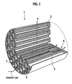
- FIG. 1 shows an embodiment of the catalytic converter of the present invention. Note that, in FIG. 1 , a catalytic converter cut away on dotted lines is shown for convenience of explanation.
- a catalytic converter 1 is columnar, and uses a three-dimensional structural support 2 having a plurality of cells 4 partitioned by cell walls 3.
- the three-dimensional structural support 2 uses, as filter elements, the cell walls 3 including a plurality of pores with a diameter sufficient for removing particulates from exhaust gas.
- the plurality of cells 4 are formed in parallel to one another by the cell walls 3.
- the exhaust gas flows into the three-dimensional structural support 2 from each cell opened at the cell inlet 5 of the three-dimensional structural support 2, flows into the cells 4 adjacent to the above-described opened cell through the plurality of pores of the cell walls 3, and is emitted through the cell outlets 6 at an opened end.
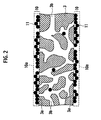
- the catalytic converter 1 of the present invention is composed by coating a catalyst-coated layer 10, which contains a catalyst component 11, on the three-dimensional structural support 2.
- the catalyst component 11 is locally present in vicinities of surfaces 3a of the three-dimensional structural support 2.
- that the catalyst component 11 is locally present stands for that at least 50% of a total amount of the catalyst component 11, which is supported on the three-dimensional structural support 2, is present in a region from the surfaces 3a of each cell wall 3 of the three-dimensional structural support 2 to surfaces 10a of the catalyst-coated layer 10 on a cross section of the catalytic converter 1.
- a ratio of the catalyst component 11 that has entered the pores 3b of each cell wall 3 of the three-dimensional structural support 2 be less than 50% of the total supported amount of the catalyst component 11 on the three-dimensional structural support 2.
- a relatively large amount of the catalyst component is supported in insides of pores of the three-dimensional structural support.
- the catalytic converter 1 of the present invention has such a cross-sectional structure as described above in an inside thereof, the supported amount of the catalyst on the surfaces of each cell wall is large.
- the particulates are accumulated on surfaces of such a heat-resistant filter, and hardly enter the insides of the pores. Therefore, in the catalytic converter of the present invention, contact interfaces between the particulates and the catalyst component 11 are increased.
- the catalyst component 11 can be utilized effectively, and catalyst activity of the catalytic converter can be enhanced.
- the ratio of the catalyst component 11 that has entered the pores 3b of each cell wall 3 of the three-dimensional structural support 2 be less than 20% of the total supported amount of the catalyst component 11 on the three-dimensional structural support 2.
- the coated amount (supported amount on the catalyst-coated layer) of the catalyst component As shown in FIGS. 5 to 7 , which percent in a total catalyst area the catalyst component occupies on the surface of each cell wall just needs to be measured on an SEM picture.
- the SEM picture is taken from a region of 200x200 ⁇ m with a corner portion in the cell of the three-dimensional structural support being taken as a center.
- the catalyst component contain a metal oxide from a viewpoint of burning the particulates by a catalytic function.
- the metal oxide there can be used cerium oxide (CeO 2 ), praseodymium oxide (Pr 6 O 11 ), yttrium oxide (Y 2 O 3 ), bismuth oxide (Bi 2 O 3 ), zirconium oxide (ZrO 2 ), or aluminum oxide (Al 2 O 3 ), or an arbitrary combination thereof.
- the catalyst component there can be suitably used platinum (Pt), palladium (Pd), rhodium (Rh), silver (Ag) or gold (Au), or a combination thereof.
- a catalyst component can be suitably used, in which Pt, Pd, Rh, Ag, Au or the like is supported on the above-described metal oxide.
- the catalyst-coated layer contains the catalyst component as described above, besides this, the catalyst-coated layer can contain iron oxide (FeO, Fe 2 O 3 , Fe 3 O 4 ), manganese oxide (MnO, Mn 2 O 3 ,MnO 2 ), or the like.
- a three-dimensional structural support which has a plurality of cells partitioned by cell walls, in which a pore diameter of the cell walls is 10 ⁇ m to 50 ⁇ m, and porosity of the cell walls is 40 vol% or more.
- a heat-resistant filter such as a ceramic-made honeycomb support, a ceramic foam filter and a metal foam filter can be used.
- an upper limit of the porosity of the cell walls is set at 70 vol% or less from a viewpoint of maintaining strength of the three-dimensional structural support itself:
- a heat-resistant filter of a wall flow type can be used particularly preferably.
- the heat-resistant filter of the wall flow type is a honeycomb support having the following configuration. Specifically, as shown in FIG. 1 , the cells in which one ends are sealed and are opened are alternately adjacent on one end surface of the support, and the sealed ends are arranged inversely between the one end surface of the support and the other end surface thereof.
- a material of the three-dimensional support cordierite, silicon carbide and the like can be mentioned as the ceramics, and ferrite-series stainless steel and the like can be mentioned as the foamed metal.
- the porosity indicates a volume ratio of all the pores with respect to a total volume of the cell walls as porous bodies, and can be obtained by the Archimedean method. Moreover, the pore diameter of the pores in the cell walls can be obtained by the mercury porosimetry.
- a first manufacturing method the following steps are performed in the event of manufacturing the above-described catalytic converter, which are: the step of dispersing, in a solvent, powder of the catalyst component and a disappearing material disappearing by heat, thereby obtaining a slurry; the step of coating the obtained slurry on the above-described three-dimensional structural support; and the baking step for eliminating the disappearing material after coating the slurry.
- the catalytic converter is manufactured in such a manner, whereby the catalyst component can be made to positively gather on the surfaces of each cell wall of the support, and can be made locally present thereon. Accordingly, the catalyst activity is enhanced.
- a mechanism that enables the catalyst component to be locally present by using the disappearing material is not necessarily obvious.
- the mechanism is considered to be as follows, for Example, as shown in FIG. 3 . First, the pores 3b in the cell wall 3 of the support 2 are closed by carbon particles as the disappearing material 12. Thereafter, the catalyst component 11 is coated on the surfaces 3a of the cell wall 3, and the carbon particles disappear by the baking step. In such a way, only a very small amount of the catalyst component 11 enters the insides of the pores 3b in the support 2.
- FIG. 4 Another mechanism is considered to be as follows as shown in FIG. 4 .
- the catalyst component 11 is adhered onto circumferences of the carbon particles serving as the disappearing material 12 owing to attractive force caused by electric charge.
- the carbon particles onto which the catalyst component 11 is adhered remains on the surfaces 3 a of the cell wall 3 of the support 2, and do not enter the insides of the pores 3b in the support 2.
- a second manufacturing method is characterized in that the following steps are performed in the event of manufacturing the above-mentioned catalytic converter, which are: the step of dispersing, in a solvent, a disappearing material disappearing by heat, thereby obtaining a slurry of the disappearing material; the step of coating the slurry of the disappearing material on the above-described three-dimensional structural support, followed by drying, thereby forming a disappearing material-coated layer; the step of further coating a catalyst slurry, in which powder of the catalyst component is dispersed, on the three-dimensional structural support on which the disappearing material-coated layer is formed; and the baking step for eliminating the disappearing material after coating the catalyst slurry.
- the disappearing material-coated layer is formed on the three-dimensional structural support, whereby the disappearing material is filled into the pores present in the cell wall of the support, and thereafter, the catalyst component is coated thereon, whereby the catalyst component is prevented from entering the insides of the pores.
- the disappearing material there can be used activated carbon, polymer resin beads, cellulose, or chaff, or an arbitrary combination thereof.
- the polymer resin beads it is suitable to use polystyrene beads or polypropylene beads. Use of such disappearing materials is effective since the use makes it easy to fix the catalyst component on the surfaces of the support, and allows the disappearing materials to disappear quickly.
- a SiC-made honeycomb support was prepared, in which a diameter was 144 mm, a height was 152 mm, a cell density was 400/in 2 , a center pore diameter in the cell wall was 10 to 20 ⁇ m, and porosity was 50 to 60 vol%.
- This honeycomb support was immersed into the above-described catalyst slurry, and excessive catalyst slurry was then removed therefrom, followed by drying at 150°C for two hours and baking at 400°C for four hours. In such a way, a catalyst layer was formed on the honeycomb support, and a catalytic converter of this Example was obtained. A formed amount of the catalyst layer was 50 g per liter of the catalytic converter.
- FIG. 5 shows the SEM picture of a vicinity of the corner of the honeycomb in the catalytic converter of this Example. From FIG. 5 , the following is understood. Specifically, a major part of the catalyst component 11 that looks white forms a shape (L shape) resembling a shape of the corner of the honeycomb, is locally present on the surface 3a of the cell wall 3 of the support, and forms the catalyst-coated layer 10. In addition, white points are hardly present in the insides of the pores 3b in the support, and the catalyst component 11 hardly enters the insides of the pores 3b in the support.
- L shape shape
- Example 2 the SiC-made honeycomb support used in Example 1 was prepared, and was immersed into the catalyst slurry, and excessive catalyst slurry was then removed therefrom, followed by drying at 150°C for two hours and baking at 400°C for four hours. In such a way, a catalyst layer was formed on the honeycomb support, and a catalytic converter of this Example was obtained. A formed amount of the catalyst layer was 50 g per liter of the catalytic converter. 82% of the total supported amount of the catalyst component was coated on the surface of the support.
- Example 2 the SiC-made honeycomb support used in Example 1 was prepared, and was immersed into the catalyst slurry, and excessive catalyst slurry was then removed therefrom, followed by drying at 150°C for two hours and baking at 400°C for four hours. In such a way, a catalyst layer was formed on the honeycomb support, and a catalytic converter of this Example was obtained. A formed amount of the catalyst layer was 50 g per liter of the catalytic converter. 82% of the total supported amount of the catalyst component was coated on the surface of the support.
- Example 2 Thereafter, the SiC-made honeycomb support used in Example 1 was prepared, and was immersed into the catalyst slurry, and excessive catalyst slurry was then removed therefrom, followed by drying at 150°C for two hours and baking at 400°C for four hours. In such a way, a catalyst layer was formed on the honeycomb support, and a catalytic converter of this Example was obtained. A formed amount of the catalyst layer was 50 g per liter of the catalytic converter. 80% of the total supported amount of the catalyst component was coated on the surface of the support.
- Example 1 the SiC-made honeycomb support used in Example 1 was prepared, and was immersed into the activated carbon suspension (disappearing material slurry), and an excessive suspension was removed therefrom, followed by drying at 150°C for two hours.
- a formed amount of an activated carbon layer (disappearing material-coated layer) was 12.5 g per liter of the honeycomb support.
- the honeycomb support on which the activated carbon layer was formed was immersed into the catalyst slurry, and excessive catalyst slurry was then removed therefrom, followed by drying at 150°C for two hours and baking at 400°C for four hours.
- a catalyst layer was formed on the honeycomb support, and a catalytic converter of this Example was obtained.
- a formed amount of the catalyst layer was 50 g per liter of the catalytic converter. 85% of the total supported amount of the catalyst component was coated on the surface of the support.
- a honeycomb support on which an activated carbon layer (disappearing material-coated layer) was formed was prepared in a same manner to Example 5.
- the honeycomb support on which the activated carbon layer was formed was immersed into the catalyst slurry, and excessive catalyst slurry was then removed therefrom, followed by drying at 150°C for two hours and baking at 400°C for four hours.
- a catalyst layer was formed on the honeycomb support, and a catalytic converter of this Example was obtained.
- a formed amount of the catalyst layer was 50 g per liter of the catalytic converter. 82% of the total supported amount of the catalyst component was coated on the surface of the support.
- a honeycomb support on which an activated carbon layer (disappearing material-coated layer) was formed was prepared in a same manner to Example 5.
- the honeycomb support on which the activated carbon layer was formed was immersed into the catalyst slurry, and excessive catalyst slurry was then removed therefrom, followed by drying at 150°C for two hours and baking at 400°C for four hours.
- a catalyst layer was formed on the honeycomb support, and a catalytic converter of this Example was obtained.
- a formed amount of the catalyst layer was 50 g per liter of the catalytic converter. 81 % of the total supported amount of the catalyst component was coated on the surface of the support.
- a honeycomb support on which an activated carbon layer (disappearing material-coated layer) was formed was prepared in a same manner to Example 5.
- Example 4 450 g of the platinum-supported aluminum oxide powder prepared in Example 4, and 50 g of alumina sol were mixed into 2000 g of water, followed by stirring, whereby a catalyst slurry was prepared.
- the honeycomb support on which the activated carbon layer was formed was immersed into the catalyst slurry, and excessive catalyst slurry was then removed therefrom, followed by drying at 150°C for two hours and baking at 400°C for four hours.
- a catalyst layer was formed on the honeycomb support, and a catalytic converter of this Example was obtained.
- a formed amount of the catalyst layer was 50 g per liter of the catalytic converter. 80% of the total supported amount of the catalyst component was coated on the surface of the support.
- Example 2 Same operations to those of Example 1 were repeated except that the activated carbon of Example 1 was replaced by polystyrene beads, whereby a catalytic converter of this Example was obtained.
- a formed amount of the catalyst layer was 50 g per liter of the catalytic converter. 61 % of the total supported amount of the catalyst component was coated on the surface of the support.
- Example 2 Same operations to those of Example 2 were repeated except that the activated carbon of Example 2 was replaced by polystyrene beads, whereby a catalytic converter of this Example was obtained.
- a formed amount of the catalyst layer was 50 g per liter of the catalytic converter. 59% of the total supported amount of the catalyst component was coated on the surface of the support.
- Example 3 Same operations to those of Example 3 were repeated except that the activated carbon of Example 3 was replaced by polystyrene beads, whereby a catalytic converter of this Example was obtained.
- a formed amount of the catalyst layer was 50 g per liter of the catalytic converter. 62% of the total supported amount of the catalyst component was coated on the surface of the support.
- Example 4 Same operations to those of Example 4 were repeated except that the activated carbon of Example 4 was replaced by polystyrene beads, whereby a catalytic converter of this Example was obtained.
- a formed amount of the catalyst layer was 50 g per liter of the catalytic converter. 62% of the total supported amount of the catalyst component was coated on the surface of the support.
- Example 2 the SiC-made honeycomb support used in Example 1 was prepared, and was immersed into the slurry, and excessive slurry was then removed therefrom, followed by drying at 150°C for two hours and baking at 400°C for four hours. In such a way, a catalyst layer was formed on the honeycomb support, and a catalytic converter of this Example was obtained. A formed amount of the catalyst layer was 50 g per liter of the catalytic converter.
- FIG. 6 shows an SEM picture of a vicinity of a corner of the honeycomb in the catalytic converter of this Example. It is understood that, unlike FIG. 5 , the catalyst component 11 that looks white enters considerably the insides of the pores 3b in the support, and the amount of the catalyst component 11 locally present on the surface 3a of the cell wall 3 is small. Note that 35% of the total supported amount of the catalyst component was coated on the surface of the support.
- Example 2 the SiC-made honeycomb support used in Example 1 was prepared, and was immersed into the slurry, and excessive slurry was then removed therefrom, followed by drying at 150°C for two hours and baking at 400°C for four hours. In such a way, a catalyst layer was formed on the honeycomb support, and a catalytic converter of this Example was obtained. A formed amount of the catalyst layer was 50 g per liter of the catalytic converter. 8% of the total supported amount of the catalyst component was coated on the surface of the support.
- Example 2 the SiC-made honeycomb support used in Example 1 was prepared, and was immersed into the slurry, and excessive slurry was then removed therefrom, followed by drying at 150°C for two hours and baking at 400°C for four hours. In such a way, a catalyst layer was formed on the honeycomb support, and a catalytic converter of this Example was obtained. A formed amount of the catalyst layer was 50 g per liter of the catalytic converter. 7% of the total supported amount of the catalyst component was coated on the surface of the support.
- a dinitrodiamine platinum solution and 450 g of aluminum oxide powder were mixed into 1000 g of water, whereby platinum was impregnated and supported onto the aluminum oxide powder.
- a supported amount of the platinum was set at 8%.
- Example 2 the SiC-made honeycomb support used in Example 1 was prepared, and was immersed into the catalyst slurry, and excessive slurry was then removed therefrom, followed by drying at 150°C for two hours and baking at 400°C for four hours. In such a way, a catalyst layer was formed on the honeycomb support, and a catalytic converter of this Example was obtained. A formed amount of the catalyst layer was 50 g per liter of the catalytic converter.
- FIG. 7 shows an SEM picture of a vicinity of a corner of the honeycomb support in the catalytic converter of this Example. It is understood that, unlike FIG. 5 , a large amount of the catalyst component 11 that looks white enters the insides of the pores 3b in the support. Note that 7% of the total supported amount of the catalyst component was coated on the surface of the support.
- the catalytic converters in which the catalyst layers fabricated in Examples 1 to 12 and Comparative Examples 1 to 4 were formed were partially hollowed. In such a way, test pieces, each of which had a capacity of 0.076 L, were cut out and the test pieces were then evaluated.
- catalyst performance was evaluated by using a fixed-bed flowing reactor. An oxygen concentration in reaction gas was 5%, and nitrogen was used as balance gas. Conditions were set such that a temperature of gas that entered the catalytic converters was 500°C and space velocity thereof was 50000 per hour. Under these conditions, the performance of each of the catalytic converters was compared with those of the others based on amounts of CO and CO 2 generated for five minutes by oxidation of the soot.
- the catalytic converter according to the present invention can be applied not only to the PM treatment in the diesel engine but also to an air purifying filter and the like.
Landscapes
- Chemical & Material Sciences (AREA)
- Engineering & Computer Science (AREA)
- Chemical Kinetics & Catalysis (AREA)
- Organic Chemistry (AREA)
- Materials Engineering (AREA)
- Oil, Petroleum & Natural Gas (AREA)
- Analytical Chemistry (AREA)
- General Chemical & Material Sciences (AREA)
- Environmental & Geological Engineering (AREA)
- Biomedical Technology (AREA)
- Health & Medical Sciences (AREA)
- Combustion & Propulsion (AREA)
- Manufacturing & Machinery (AREA)
- Mechanical Engineering (AREA)
- Catalysts (AREA)
- Exhaust Gas After Treatment (AREA)
- Exhaust Gas Treatment By Means Of Catalyst (AREA)
- Processes For Solid Components From Exhaust (AREA)
Applications Claiming Priority (2)
| Application Number | Priority Date | Filing Date | Title |
|---|---|---|---|
| JP2007029886 | 2007-02-09 | ||
| JP2007264054 | 2007-10-10 |
Publications (3)
| Publication Number | Publication Date |
|---|---|
| EP1961481A2 true EP1961481A2 (de) | 2008-08-27 |
| EP1961481A3 EP1961481A3 (de) | 2008-10-22 |
| EP1961481B1 EP1961481B1 (de) | 2012-09-05 |
Family
ID=39432517
Family Applications (1)
| Application Number | Title | Priority Date | Filing Date |
|---|---|---|---|
| EP08002386A Ceased EP1961481B1 (de) | 2007-02-09 | 2008-02-08 | Herstellungsverfahren für Katalysator |
Country Status (3)
| Country | Link |
|---|---|
| US (1) | US8158195B2 (de) |
| EP (1) | EP1961481B1 (de) |
| JP (2) | JP5697299B2 (de) |
Cited By (3)
| Publication number | Priority date | Publication date | Assignee | Title |
|---|---|---|---|---|
| DE102013013973A1 (de) | 2013-08-23 | 2015-02-26 | Clariant Produkte (Deutschland) Gmbh | Partikelfilter zur Reinigung von Abgasen, Abgasreinigungssystem und Verfahren zur Reinigung von Abgas |
| JP2015077532A (ja) * | 2013-10-15 | 2015-04-23 | 本田技研工業株式会社 | 排気浄化フィルタ |
| WO2025163277A1 (en) | 2024-01-30 | 2025-08-07 | Johnson Matthey Public Limited Company | Method of making ceramic wall-flow filter substrate supporting porous on-wall coating |
Families Citing this family (19)
| Publication number | Priority date | Publication date | Assignee | Title |
|---|---|---|---|---|
| WO2009100097A2 (en) | 2008-02-05 | 2009-08-13 | Basf Catalysts Llc | Gasoline engine emissions treatment systems having particulate traps |
| CN102046561A (zh) * | 2008-05-30 | 2011-05-04 | 康宁股份有限公司 | 低背压的多孔蜂窝体及其制备方法 |
| JP2010269270A (ja) * | 2009-05-22 | 2010-12-02 | Sumitomo Osaka Cement Co Ltd | ハニカム構造型フィルタ |
| EP2435673B1 (de) * | 2009-05-29 | 2022-08-03 | Corning Inc. | Partikelfilter mit einer mit wenig russ beladenen beschichtung |
| US8815189B2 (en) | 2010-04-19 | 2014-08-26 | Basf Corporation | Gasoline engine emissions treatment systems having particulate filters |
| US20120150495A1 (en) * | 2010-12-08 | 2012-06-14 | GM Global Technology Operations LLC | Three-dimensional catalytic converter modeling |
| JP6712272B2 (ja) * | 2014-12-19 | 2020-06-17 | ジョンソン、マッセイ、パブリック、リミテッド、カンパニーJohnson Matthey Public Limited Company | 触媒製造方法 |
| US9827562B2 (en) | 2015-10-05 | 2017-11-28 | GM Global Technology Operations LLC | Catalytic converters with age-suppressing catalysts |
| US9855547B2 (en) | 2015-10-05 | 2018-01-02 | GM Global Technology Operations LLC | Low-temperature oxidation catalysts |
| US10422036B2 (en) | 2015-10-23 | 2019-09-24 | GM Global Technology Operations LLC | Suppressing aging of platinum group metal particles in a catalytic converter |
| RU2018128585A (ru) * | 2016-01-07 | 2020-02-07 | Джонсон Мэтти Джапан Г.К. | Фильтр |
| JP6297767B2 (ja) * | 2016-03-24 | 2018-03-20 | 株式会社キャタラー | 排ガス浄化装置 |
| US9901907B1 (en) | 2016-08-31 | 2018-02-27 | GM Global Technology Operations LLC | Catalytic converters with age-suppressing catalysts |
| US10035133B2 (en) | 2016-10-25 | 2018-07-31 | GM Global Technology Operations LLC | Catalysts with atomically dispersed platinum group metal complexes and a barrier disposed between the complexes |
| EP3590598A4 (de) * | 2017-03-03 | 2021-01-06 | N.E. Chemcat Corporation | Filter zur abgasreinigung und verfahren zur herstellung davon |
| CN108295849B (zh) * | 2018-01-18 | 2021-06-22 | 中国科学院宁波材料技术与工程研究所 | My/LaxSr1-xTi1-yO3催化剂、其制法及应用 |
| DE102018127957A1 (de) * | 2018-11-08 | 2020-05-14 | Umicore Ag & Co. Kg | Partikelfilter mit mehreren Beschichtungen |
| DE102018127955A1 (de) | 2018-11-08 | 2020-05-14 | Umicore Ag & Co. Kg | Katalytisch aktiver Partikelfilter mit hoher Filtrationseffizienz |
| GB201908450D0 (en) | 2019-06-12 | 2019-07-24 | Johnson Matthey Davy Technologies Ltd | Process for synthesising methanol |
Citations (4)
| Publication number | Priority date | Publication date | Assignee | Title |
|---|---|---|---|---|
| JP2001187344A (ja) | 2000-01-05 | 2001-07-10 | Matsushita Electric Ind Co Ltd | 排ガス浄化材及び排ガス浄化装置 |
| JP2002102621A (ja) | 2000-09-28 | 2002-04-09 | Matsushita Electric Ind Co Ltd | 排ガス浄化材およびその製造方法 |
| EP1475151A1 (de) | 2002-02-15 | 2004-11-10 | ICT Co., Ltd. | Katalysator zur reinigung der abgasemission einer brennkraftmaschine, herstellungsverfahren dafür und verfahren zur reinigung der abgasemission einer brennkraftmaschine |
| EP1728618A1 (de) | 2005-05-20 | 2006-12-06 | Institute of Nuclear Energy Research | Methoden zur Herstellung von Platin- und Platinlegierungskatalysatoren mit Nanonetzwerkstruktur |
Family Cites Families (14)
| Publication number | Priority date | Publication date | Assignee | Title |
|---|---|---|---|---|
| DE1266279B (de) | 1963-05-30 | 1968-04-18 | Erdoelchemie Gmbh | Verfahren zur Herstellung von poroesen Silber- und Kupferkatalysatoren |
| CA1260909A (en) * | 1985-07-02 | 1989-09-26 | Koichi Saito | Exhaust gas cleaning catalyst and process for production thereof |
| JPH08215522A (ja) * | 1994-12-15 | 1996-08-27 | Matsushita Electric Ind Co Ltd | 排ガスフィルター及びその製造方法 |
| JP3750178B2 (ja) | 1995-04-05 | 2006-03-01 | 株式会社デンソー | 排ガス浄化用フィルタ及びその製造方法 |
| US5846276A (en) * | 1995-07-05 | 1998-12-08 | Matsushita Electric Industrial Co., Ltd. | Exhaust gas filter |
| JP3707843B2 (ja) * | 1995-12-08 | 2005-10-19 | 株式会社日本自動車部品総合研究所 | ディーゼル排ガス浄化フィルタ |
| DE19806266C1 (de) * | 1998-02-16 | 1999-08-26 | Siemens Ag | Katalysator und Verfahren zur Abgasreinigung |
| JP4427658B2 (ja) * | 1998-07-07 | 2010-03-10 | コーニング インコーポレイテッド | ディーゼル排出ガスフィルター |
| JP2003210922A (ja) * | 2002-01-23 | 2003-07-29 | Ibiden Co Ltd | セラミックハニカムフィルタ |
| DE60313151T2 (de) * | 2002-02-28 | 2007-12-27 | Csir, Pretoria | Behandlung von abgasen aus einem verbrennungsmotor |
| ATE481151T1 (de) | 2003-02-28 | 2010-10-15 | Ibiden Co Ltd | Keramische wabenstruktur |
| KR20040086981A (ko) | 2003-04-03 | 2004-10-13 | 박죽랑 | 정수장오니를 활용한 경량촉매벽돌 제조방법 |
| EP1632288B1 (de) | 2004-09-03 | 2012-06-20 | Mazda Motor Corporation | Abgasreinigungskatalysator und Sauerstoffspeicherkomponente dafür |
| US20060140843A1 (en) * | 2004-12-23 | 2006-06-29 | In-Kyung Sung | Macroporous structures for heterogeneous catalyst support |
-
2008
- 2008-01-29 US US12/021,795 patent/US8158195B2/en not_active Expired - Fee Related
- 2008-02-05 JP JP2008025272A patent/JP5697299B2/ja not_active Expired - Fee Related
- 2008-02-08 EP EP08002386A patent/EP1961481B1/de not_active Ceased
-
2013
- 2013-06-21 JP JP2013130706A patent/JP5747952B2/ja not_active Expired - Fee Related
Patent Citations (4)
| Publication number | Priority date | Publication date | Assignee | Title |
|---|---|---|---|---|
| JP2001187344A (ja) | 2000-01-05 | 2001-07-10 | Matsushita Electric Ind Co Ltd | 排ガス浄化材及び排ガス浄化装置 |
| JP2002102621A (ja) | 2000-09-28 | 2002-04-09 | Matsushita Electric Ind Co Ltd | 排ガス浄化材およびその製造方法 |
| EP1475151A1 (de) | 2002-02-15 | 2004-11-10 | ICT Co., Ltd. | Katalysator zur reinigung der abgasemission einer brennkraftmaschine, herstellungsverfahren dafür und verfahren zur reinigung der abgasemission einer brennkraftmaschine |
| EP1728618A1 (de) | 2005-05-20 | 2006-12-06 | Institute of Nuclear Energy Research | Methoden zur Herstellung von Platin- und Platinlegierungskatalysatoren mit Nanonetzwerkstruktur |
Cited By (3)
| Publication number | Priority date | Publication date | Assignee | Title |
|---|---|---|---|---|
| DE102013013973A1 (de) | 2013-08-23 | 2015-02-26 | Clariant Produkte (Deutschland) Gmbh | Partikelfilter zur Reinigung von Abgasen, Abgasreinigungssystem und Verfahren zur Reinigung von Abgas |
| JP2015077532A (ja) * | 2013-10-15 | 2015-04-23 | 本田技研工業株式会社 | 排気浄化フィルタ |
| WO2025163277A1 (en) | 2024-01-30 | 2025-08-07 | Johnson Matthey Public Limited Company | Method of making ceramic wall-flow filter substrate supporting porous on-wall coating |
Also Published As
| Publication number | Publication date |
|---|---|
| JP2013226557A (ja) | 2013-11-07 |
| JP5697299B2 (ja) | 2015-04-08 |
| EP1961481A3 (de) | 2008-10-22 |
| US8158195B2 (en) | 2012-04-17 |
| JP5747952B2 (ja) | 2015-07-15 |
| JP2009106926A (ja) | 2009-05-21 |
| EP1961481B1 (de) | 2012-09-05 |
| US20080317646A1 (en) | 2008-12-25 |
Similar Documents
| Publication | Publication Date | Title |
|---|---|---|
| US8158195B2 (en) | Catalytic converter and manufacturing method thereof | |
| JP5273446B2 (ja) | 排ガス浄化用触媒及びその製造方法 | |
| KR100692356B1 (ko) | 벌집형 구조체 | |
| JP5447757B2 (ja) | 触媒被覆された粒子フィルタ及びその製造方法並びにその使用 | |
| EP1919613B1 (de) | Dieselabgasartikel und katalysatorzusammensetzungen dafür | |
| KR101051874B1 (ko) | 팔라듐-금을 함유하는 엔진 배기가스 촉매 | |
| EP2105200B1 (de) | Katalysator beschichteter filter | |
| EP1925362A1 (de) | Abgaskatalysatoren mit Palladiumgold für Motoren | |
| EP3192584B1 (de) | Abgasreinigungskatalysator | |
| JP5775512B2 (ja) | ハニカムフィルタ及びハニカムフィルタの製造方法 | |
| CN111980785B (zh) | 废气净化装置 | |
| WO2005037406A1 (ja) | ハニカム構造体 | |
| EP1679119B1 (de) | Verfahren zur Herstellung eines Katalysators zur Reinigung von Abgasen einer diesel Brennkraftmaschine | |
| JP2009285605A (ja) | 排ガス浄化用触媒 | |
| JP2011513060A (ja) | 気体濾過構造 | |
| JP5146752B2 (ja) | 排ガス浄化用触媒の製造方法 | |
| EP3581272B1 (de) | Katalysator zur abgasreinigung | |
| JP4471621B2 (ja) | ハニカム構造体 | |
| JP3874246B2 (ja) | ディーゼル排ガス浄化用フィルタ型触媒 | |
| KR20080034490A (ko) | 허니컴 구조체, 허니컴 구조체의 제조 방법 및 배기 가스정화 장치 | |
| JP3876731B2 (ja) | 触媒担体構造体と排気ガス浄化用触媒 | |
| EP1961482A1 (de) | Katalysatorträger | |
| EP2177264B1 (de) | Abgasreinigungsfilter bestehend aus einem Abgasreinigungskatalysator für die Entfernung von Feststoffen und sein Herstellungsverfahren | |
| JP2006314894A (ja) | 排ガス浄化用触媒の製造方法 | |
| JP2018161618A (ja) | 触媒付きパティキュレートフィルタの製造方法 |
Legal Events
| Date | Code | Title | Description |
|---|---|---|---|
| PUAI | Public reference made under article 153(3) epc to a published international application that has entered the european phase |
Free format text: ORIGINAL CODE: 0009012 |
|
| 17P | Request for examination filed |
Effective date: 20080208 |
|
| AK | Designated contracting states |
Kind code of ref document: A2 Designated state(s): AT BE BG CH CY CZ DE DK EE ES FI FR GB GR HR HU IE IS IT LI LT LU LV MC MT NL NO PL PT RO SE SI SK TR |
|
| AX | Request for extension of the european patent |
Extension state: AL BA MK RS |
|
| PUAL | Search report despatched |
Free format text: ORIGINAL CODE: 0009013 |
|
| RIC1 | Information provided on ipc code assigned before grant |
Ipc: B01D 53/94 20060101AFI20080610BHEP Ipc: B22F 3/11 20060101ALI20080904BHEP Ipc: B01J 35/04 20060101ALI20080904BHEP Ipc: F01N 3/035 20060101ALI20080904BHEP |
|
| AK | Designated contracting states |
Kind code of ref document: A3 Designated state(s): AT BE BG CH CY CZ DE DK EE ES FI FR GB GR HR HU IE IS IT LI LT LU LV MC MT NL NO PL PT RO SE SI SK TR |
|
| AX | Request for extension of the european patent |
Extension state: AL BA MK RS |
|
| 17Q | First examination report despatched |
Effective date: 20090507 |
|
| AKX | Designation fees paid |
Designated state(s): DE FR GB |
|
| GRAP | Despatch of communication of intention to grant a patent |
Free format text: ORIGINAL CODE: EPIDOSNIGR1 |
|
| RIC1 | Information provided on ipc code assigned before grant |
Ipc: B22F 3/11 20060101ALI20120123BHEP Ipc: B01D 53/94 20060101AFI20120123BHEP Ipc: F01N 3/035 20060101ALI20120123BHEP Ipc: B01J 35/04 20060101ALI20120123BHEP |
|
| RTI1 | Title (correction) |
Free format text: MANUFACTURING METHOD FOR CATALALYTIC CONVERTER |
|
| GRAS | Grant fee paid |
Free format text: ORIGINAL CODE: EPIDOSNIGR3 |
|
| GRAA | (expected) grant |
Free format text: ORIGINAL CODE: 0009210 |
|
| RAP1 | Party data changed (applicant data changed or rights of an application transferred) |
Owner name: NISSAN MOTOR CO., LTD. |
|
| AK | Designated contracting states |
Kind code of ref document: B1 Designated state(s): DE FR GB |
|
| REG | Reference to a national code |
Ref country code: GB Ref legal event code: FG4D |
|
| REG | Reference to a national code |
Ref country code: DE Ref legal event code: R096 Ref document number: 602008018504 Country of ref document: DE Effective date: 20121031 |
|
| PLBE | No opposition filed within time limit |
Free format text: ORIGINAL CODE: 0009261 |
|
| STAA | Information on the status of an ep patent application or granted ep patent |
Free format text: STATUS: NO OPPOSITION FILED WITHIN TIME LIMIT |
|
| 26N | No opposition filed |
Effective date: 20130606 |
|
| REG | Reference to a national code |
Ref country code: DE Ref legal event code: R097 Ref document number: 602008018504 Country of ref document: DE Effective date: 20130606 |
|
| REG | Reference to a national code |
Ref country code: FR Ref legal event code: PLFP Year of fee payment: 9 |
|
| REG | Reference to a national code |
Ref country code: FR Ref legal event code: PLFP Year of fee payment: 10 |
|
| REG | Reference to a national code |
Ref country code: FR Ref legal event code: PLFP Year of fee payment: 11 |
|
| PGFP | Annual fee paid to national office [announced via postgrant information from national office to epo] |
Ref country code: FR Payment date: 20230119 Year of fee payment: 16 |
|
| PGFP | Annual fee paid to national office [announced via postgrant information from national office to epo] |
Ref country code: GB Payment date: 20230121 Year of fee payment: 16 Ref country code: DE Payment date: 20230119 Year of fee payment: 16 |
|
| REG | Reference to a national code |
Ref country code: DE Ref legal event code: R084 Ref document number: 602008018504 Country of ref document: DE |
|
| REG | Reference to a national code |
Ref country code: GB Ref legal event code: 746 Effective date: 20231002 |
|
| REG | Reference to a national code |
Ref country code: DE Ref legal event code: R119 Ref document number: 602008018504 Country of ref document: DE |
|
| GBPC | Gb: european patent ceased through non-payment of renewal fee |
Effective date: 20240208 |
|
| PG25 | Lapsed in a contracting state [announced via postgrant information from national office to epo] |
Ref country code: DE Free format text: LAPSE BECAUSE OF NON-PAYMENT OF DUE FEES Effective date: 20240903 |
|
| PG25 | Lapsed in a contracting state [announced via postgrant information from national office to epo] |
Ref country code: GB Free format text: LAPSE BECAUSE OF NON-PAYMENT OF DUE FEES Effective date: 20240208 |
|
| PG25 | Lapsed in a contracting state [announced via postgrant information from national office to epo] |
Ref country code: FR Free format text: LAPSE BECAUSE OF NON-PAYMENT OF DUE FEES Effective date: 20240229 |
|
| PG25 | Lapsed in a contracting state [announced via postgrant information from national office to epo] |
Ref country code: GB Free format text: LAPSE BECAUSE OF NON-PAYMENT OF DUE FEES Effective date: 20240208 Ref country code: FR Free format text: LAPSE BECAUSE OF NON-PAYMENT OF DUE FEES Effective date: 20240229 Ref country code: DE Free format text: LAPSE BECAUSE OF NON-PAYMENT OF DUE FEES Effective date: 20240903 |