EP1961516B1 - Klemmvorrichtung und solch eine vorrichtung verwendendes klemmsystem - Google Patents
Klemmvorrichtung und solch eine vorrichtung verwendendes klemmsystem Download PDFInfo
- Publication number
- EP1961516B1 EP1961516B1 EP06833131A EP06833131A EP1961516B1 EP 1961516 B1 EP1961516 B1 EP 1961516B1 EP 06833131 A EP06833131 A EP 06833131A EP 06833131 A EP06833131 A EP 06833131A EP 1961516 B1 EP1961516 B1 EP 1961516B1
- Authority
- EP
- European Patent Office
- Prior art keywords
- rigid sleeve
- clamping
- clamping apparatus
- hole
- reference block
- Prior art date
- Legal status (The legal status is an assumption and is not a legal conclusion. Google has not performed a legal analysis and makes no representation as to the accuracy of the status listed.)
- Not-in-force
Links
Images




Classifications
-
- B—PERFORMING OPERATIONS; TRANSPORTING
- B23—MACHINE TOOLS; METAL-WORKING NOT OTHERWISE PROVIDED FOR
- B23Q—DETAILS, COMPONENTS, OR ACCESSORIES FOR MACHINE TOOLS, e.g. ARRANGEMENTS FOR COPYING OR CONTROLLING; MACHINE TOOLS IN GENERAL CHARACTERISED BY THE CONSTRUCTION OF PARTICULAR DETAILS OR COMPONENTS; COMBINATIONS OR ASSOCIATIONS OF METAL-WORKING MACHINES, NOT DIRECTED TO A PARTICULAR RESULT
- B23Q3/00—Devices holding, supporting, or positioning work or tools, of a kind normally removable from the machine
- B23Q3/02—Devices holding, supporting, or positioning work or tools, of a kind normally removable from the machine for mounting on a work-table, tool-slide, or analogous part
- B23Q3/06—Work-clamping means
-
- B—PERFORMING OPERATIONS; TRANSPORTING
- B23—MACHINE TOOLS; METAL-WORKING NOT OTHERWISE PROVIDED FOR
- B23Q—DETAILS, COMPONENTS, OR ACCESSORIES FOR MACHINE TOOLS, e.g. ARRANGEMENTS FOR COPYING OR CONTROLLING; MACHINE TOOLS IN GENERAL CHARACTERISED BY THE CONSTRUCTION OF PARTICULAR DETAILS OR COMPONENTS; COMBINATIONS OR ASSOCIATIONS OF METAL-WORKING MACHINES, NOT DIRECTED TO A PARTICULAR RESULT
- B23Q1/00—Members which are comprised in the general build-up of a form of machine, particularly relatively large fixed members
- B23Q1/0063—Connecting non-slidable parts of machine tools to each other
- B23Q1/0081—Connecting non-slidable parts of machine tools to each other using an expanding clamping member insertable in a receiving hole
- B23Q1/009—Connecting non-slidable parts of machine tools to each other using an expanding clamping member insertable in a receiving hole the receiving hole being cylindrical or conical
-
- B—PERFORMING OPERATIONS; TRANSPORTING
- B23—MACHINE TOOLS; METAL-WORKING NOT OTHERWISE PROVIDED FOR
- B23Q—DETAILS, COMPONENTS, OR ACCESSORIES FOR MACHINE TOOLS, e.g. ARRANGEMENTS FOR COPYING OR CONTROLLING; MACHINE TOOLS IN GENERAL CHARACTERISED BY THE CONSTRUCTION OF PARTICULAR DETAILS OR COMPONENTS; COMBINATIONS OR ASSOCIATIONS OF METAL-WORKING MACHINES, NOT DIRECTED TO A PARTICULAR RESULT
- B23Q3/00—Devices holding, supporting, or positioning work or tools, of a kind normally removable from the machine
Definitions
- the present invention relates to a clamping apparatus for fixing a movable block such as a work pallet or a workpiece to a reference block such as a table of a machine tool, and further relates to a clamping system using the clamping apparatus.
- a known clamping apparatus is described in Japanese patent publication No. 3550010 .
- the document describes an apparatus in which a tapered outer peripheral surface at an upper portion of a pull rod makes an engagement with an inner peripheral surface of an annular collet from above, and the collet and the pull rod are arranged to be radially movable with respect to a housing.
- the known apparatus has only a function of fixing a workpiece, but does not have a function of positioning the workpiece. Therefore, when employing such an apparatus it is necessary to install in addition an exclusive positioning apparatus. As a result, the clamping system is complicated in its structure, and made large in size.
- An object of the present invention is to provide a clamping apparatus with a positioning function and a clamping system utilizing the apparatus.
- WO2004/067224-A1 discloses a clamping apparatus which clamps a movable block having a socket hole to a reference block, comprising:
- an apparatus which clamps a movable block 2 having a socket hole 3 to a reference block 1 is constructed as follows.
- a centre hole 20 is provided in the reference block 1 so as to face the socket hole 3, and the centre hole 20 has a tapered inner surface 23 narrowing toward a base end.
- a rigid sleeve 21 is supported by the reference block 1 axially movably within a predetermined range.
- the rigid sleeve 21 includes a tapered outer surface 27 making a tapering engagement with the tapered inner surface 23 of the centre hole 20, a projecting portion 25, which projects further toward a leading end than the centre hole 20 and is inserted into the socket hole 3, and an axially extending cylindrical hole 21 a.
- An advancing means 45 is provided for pressing the rigid sleeve 21 toward the leading.
- An output member 48 is inserted into the cylindrical hole 21a of the rigid sleeve 21.
- the output member 48 is connected to a clamping member 33 provided on the projecting portion 25 so as to be inserted into the socket hole 3.
- a driving means D is provided for moving the output member 48 toward the base end.
- the output member 48 moves the clamping member 33 towards the base end against the advancing means 45 and radially-outwardly for locking, and makes the tapered outer surface 27 of the rigid sleeve 21 form a tapering engagement with the tapered inner surface 23 of the centre hole 20.
- the rigid sleeve 21 is different from a sleeve which can elastically deformed diametrically, for example, as a collet or the like, but means a tubular member having extremely slight elastic deformation.
- annular clamping member such as a collet is elastically deformed to radially expand and radially contract
- clamping members are arranged circumferentially at intervals radially-outwardly and radially-inwardly and move to radially expand and radially contract.
- An automatic means utilizing a fluid power actuator or the like and a manual means utilizing screw thrust force or the like are both feasible for the drive means.
- the output member 48 raises the clamping member 33 toward the leading end (upwards in the drawing), and the clamping member 33 is changed to be in a diametrically contracted state. Further, the rigid sleeve 21 is held at a raised position by the advancing means 45.
- the movable block 2 is positioned with respect to the reference block 1, first the movable block 2 is lowered in the release state shown in Fig. 3A , and the socket hole 3 is fitted at the outside of the clamping member 33, and the movable block 2 is received by the reference block 1. Further, at the time of receiving, as illustrated in Fig. 3A , the movable block 2 may be received by the reference block 1 either via another member such as the rigid sleeve 21, or directly by the reference block 1.
- the rigid sleeve 21 is lowered against the advancing means 45, and the tapered outer surface 27 of the rigid sleeve 21 makes a tapering engagement with the tapered inner surface 23 of the centre hole 20.
- the rigid sleeve 21 is radially (i.e. horizontally) and axially (i.e. vertically) constrained by the reference block 1 by means of the tapering engagement.
- the movable block 2 is horizontally positioned with respect to the reference block 1 by means of the rigid sleeve 21 in the constrained state and the clamping member 33 in the close contact state with the socket hole 3.
- the output member 48 is driven to descend further with respect to the rigid sleeve 21, and the output member 48 presses the movable block 2 downward by means of the clamping member 33. Thereby, the supported surface 2a of the movable block 2 is strongly pressed onto the support surface 1a of the reference block 1.
- the movable block can be clamped to the reference block after the movable block is positioned with respect to the reference block by the clamping member and the rigid sleeve, a clamping apparatus with a positioning function can be made more simple and compact.
- the tapered outer surface of the rigid sleeve makes a tapering engagement with the tapered inner surface of the centre hole; consequently the rigid sleeve can be integrated with the reference block. Therefore, the rigid sleeve is enhanced in its radial (horizontal) rigidity. As a result, even when great external force such as machining reaction force during a machining process is applied to the movable block, the movable block can be held in a positioned state.
- the rigid sleeve is an independent member different from the reference block, it is possible to exchange the rigid sleeve inexpensively and easily when it is worn away. Moreover, since the rigid sleeve is an independent member, design freedom in selection of material, selection of wall thickness, surface treatment, and so on are greater; consequently to the manufacture of the rigid sleeve with high accuracy and high rigidity is facilitated. As a result, it is possible to provide a clamping apparatus which can be used in a maintenance-free manner over a long period of time.
- a flange portion 28 projects radially-outwardly from the rigid sleeve 21 outside the centre hole 20, and the advancing means 45 is disposed in an annular manner between the flange portion 28 and the reference block 1.
- the preventative means serves as the advancing means as well, the clamping apparatus has fewer components, and the clamping apparatus can be made more simple and compact.
- the annular advancing means 45 is composed of an elastic member for sealing such as rubber or synthetic resin. It is thereby possible to reliably prevent foreign matter such as swarf from intrusion into the reference block.
- a flange portion 28 projects radially-outwardly from the rigid sleeve 21 outside the centre hole 20.
- the advancing means 45 presses the movable block 2 to form a seating gap E between a supported surface 2a of the movable block 2 and a support surface 1a of the reference block 1.
- a detection hole 74 for pressurized fluid for seating confirmation is opened in the support surface 1a.
- a supply port 76 for pressurized fluid for locking confirmation is provided in the reference block 1.
- the supply port 76 is connected in communication with an exterior space via a locking gap F between the tapered inner surface 23 and the tapered outer surface 27.
- the communicative connection between the supply port 76 and the exterior space is shut off when the tapered outer surface 27 makes a tapering engagement with the tapered inner surface 23.
- a locking gap is formed in a release state, and it is possible to cause the locking gap to disappear in a lock state, it is possible distinguish reliably between the release state and the lock state for detection.
- the tapered outer surface 27 of the rigid sleeve 21 may make a tapering engagement with substantially the whole circumference of the tapered inner surface 23 of the centre hole 20 provided in the reference block 1.
- a pair of protruding portions 80, 80 radially facing each other is provided on at least one of an inner periphery of the centre hole 20 provided in the reference block 1 and an outer periphery of the rigid sleeve 21.
- the tapered inner surface 23 or the tapered outer surface 27 is formed to the respective protruding portions 80.
- Movement-allowing (i.e. relief) spaces 81, 81 partitioned by the protruding portions 80, 80 are formed to radially face each other between the inner periphery of the centre hole 20 and the outer periphery of the rigid sleeve 21.
- the clamping member 33 may be composed of a diametrically expandable and diametrically contractible collet, and the collet type clamping member 33 may make a wedge-engagement with the the rigid sleeve's leading end projecting portion 25.
- the clamping member since the clamping member makes a wedge-engagement with the rigid sleeve from the leading end side, it is easily possible to cover the wedge-engaged portion from the leading end side. Therefore, it is possible to prevent foreign matter such as swarf from intruding into the wedge-engaged portion. As a result, it is possible to use the clamping apparatus in a maintenance-free manner over a long period of time.
- the clamping member 33 may be composed of a plurality of balls 96 arranged circumferentially at intervals on a peripheral wall of the projecting portion 25 of the rigid sleeve 21, and the output member 48 changes the respective balls 96 to radially-outward engaging positions X. Further, it is preferable to provide at least three balls 96.
- the clamping member composed of the balls is arranged inside the peripheral wall of the rigid sleeve, as compared with a structure in which the clamping member is disposed at the outer periphery of the rigid sleeve, a portion to be inserted into the socket hole of the movable block can be made with a small diameter. Therefore, it is possible to provide a clamping apparatus with a simple structure suitable for a small diameter socket hole. Further, the clamping member composed of the balls can be made to provide a radially-outward movement greater than that of a collet type clamping member.
- a clamping system may comprise a clamping apparatus, according to any one of the embodiments or may comprise different embodiments of the clamping apparatus..
- Fig. 1 to Fig. 7B illustrate an embodiment of the present invention, and exemplify that a clamping apparatus in a clamping system for a work pallet.
- a reference block 1 is placed on a table T of a machine tool, and a supported surface 2a of a work pallet 2, constituting a movable block, is received on a support surface 1a of the reference block 1.
- Various socket holes 3 each composed of a circular straight hole are opened in the supported surface 2a.
- four socket holes 3 are illustrated.
- the reference block 1 includes a base plate 4 fixed to the table T.
- a first clamping apparatus 11 and a second clamping apparatus 12 each with a positioning functions and a locking function, and two ('third') clamping apparatus 13, 13 with only locking functions; there is one clamping apparatus for each socket hole 3.
- the first clamping apparatus 11 and the second clamping apparatus 12 are disposed diagonally opposite each other
- the 'third' clamping apparatuses 13, 13 are disposed diagonally opposite each other.
- each clamping apparatus 11, 12, and 13 diametrically expands a respective annular clamping member 33 (described later) radially due to wedge action, and drive clamping member 33 downward into a state where substantially the whole circumference of the peripheral wall of each annular clamping member 33 is in close contact with the respective socket hole 3 to fix the work pallet 2 to the reference block 1.
- the first clamping apparatus 11 horizontally and vertically positions a rigid sleeve 21 ( Fig. 3A ), with respect to the reference block 1 at substantially the same time as the close contact of the clamping member 33.
- the second clamping apparatus 12 positions the rigid sleeve 21 ( Fig. 6A ) in a horizontal direction substantially perpendicular to a straight line L connecting a reference axis A and a reference axis B, and vertically positions the rigid sleeve 21, thereby preventing the work pallet 2 from rotating about the axis A.
- each clamping apparatus 13 allows the rigid sleeve 21 to move horizontally with respect to the reference block 1 (refer to Fig. 7A and Fig. 7B ), and therefore, each clamping apparatus 13 has only a vertical positioning function, but does not have a horizontal positioning function.
- the first clamping apparatus 11 and the second clamping apparatus 12 have the same structure except for differences which will be described later, and basically the following structure is common thereto.
- a lower portion of a housing 15 is fitted into an installation hole 4a of the base plate 4, and a flange 16 of the housing 15 is fixed to a peripheral wall of the installation hole 4a by four tightening bolts 17.
- a centre hole 20 vertically extending is formed concentrically with the reference axis A (refer to Fig. 1 and Fig. 2A ).
- the centre hole 20 is disposed so as to face the socket hole 3.
- the rigid sleeve 21 is vertically (axially) movably inserted into the centre hole 20.
- the centre hole 20 and the rigid sleeve 21 are constructed as follows as illustrated by the enlarged view of Fig. 3A .
- Tapered inner surfaces 23, 23 are respectively formed in an upper portion and a lower portion of an inner periphery of the centre hole 20. Each tapered inner surface 23 narrows downwards (toward a base end direction).
- the rigid sleeve 21 has a base portion 24 inserted into the centre hole 20, and a projecting portion 25 capable of being inserted into the socket hole 3. The projecting portion 25 projects further upwards (toward a leading end) than an upper end of the centre hole 20.
- a tapered outer surface 27 capable of making a tapering engagement with the tapered inner surface 23 is provided on an outer peripheral surface of the base portion 24.
- the taper angles of the tapered inner surface 23 and the tapered outer surface 27 are within a range from approximately 5 degrees to approximately 23 degrees, and it is more preferable that they be be within a range from approximately 10 degrees to approximately 16 degrees.
- a flange portion 28 projects radially outwardly from a lower portion of the projecting portion 25.
- a tapered outer peripheral surface 30 which narrows upwards is formed on an upper portion of the projecting portion 25.
- a tapered inner peripheral surface 34 of the annular clamping member 33 makes a wedge-engagement with the tapered outer peripheral surface 30 of the rigid sleeve 21 from above.
- a straight outer peripheral surface 35 of the clamping member 33 is capable of being inserted into the socket hole 3 of the work pallet 2.
- the clamping member 33 is formed in a collet shape. Specifically, one vertically extending slit 36 is formed in a peripheral wall of the clamping member 33, and thereby the clamping member 33 is diametrically expandable and diametrically contractible;it diametrically contracts due to its own elastic restoring force.
- An elastic member (an advancing means) 45 is disposed between an upper portion of a peripheral wall of the centre hole 20 and the flange portion 28.
- the elastic member 45 is composed of a sealing member such as rubber or synthetic resin, and presses the rigid sleeve 21 upward (toward the leading end).
- the rigid sleeve 21 is prevented from ascending further than a predetermined distance by a stopper 47 attached at a lower portion of the rigid sleeve 21.
- An output member 48 is inserted into the housing 15 to be vertically movable therein.
- the output member 48 includes a piston 50 hermetically inserted into a cylinder hole 49 in a lower portion of the housing 15, a piston rod 52 which projects upwards from the piston 50 and is hermetically inserted into a rod hole 51, and a connecting rod 53 screwed to the piston rod 52.
- the connecting rod 53 is inserted into a cylindrical hole 21a of the rigid sleeve 21.
- An upper flange 57 of the clamping member 33 is fitted radially slidably between an upper flange 56 of the connecting rod 53 and a head portion 54 of the connecting rod 53.
- a lock means 61 and a release means 62 constituting a drive means D are provided in the housing 15.
- the lock means 61 is composed of the piston 50 and a lock chamber 63 formed above the piston 50.
- the lock chamber 63 is connected in communication with a supply and discharge port 64 for pressurized oil for the purpose of locking.
- the release means 62 is composed of the piston 50 and a release chamber 66 formed below the piston 50.
- a supply and discharge port 67 for pressurized oil for the purpose of release is connected in communication with the release chamber 66.
- a throttle pin 70 is fitted into a vertical passage of the supply and discharge passage 69 for the purpose of locking, and a throttle passage is composed of a fitting gap.
- a seating confirmation means is provided on the first clamping apparatus 11. Specifically, a detection hole 74 is opened in each support surface 1a, and compressed air for detection is supplied to each detection hole 74. Then, when the supported surface 2a of the work pallet 2 is in a contact state with the support surfaces 1a to cause a seating gap E to disappear, the pressure in the detection holes 74 increases. By detecting the increase in pressure by means of a pressure switch or the like, it is possible to confirm that the work pallet 2 is seated on the housing 15.
- a locking confirmation means is provided. Specifically, there are an air supply port 76 for passes through a lateral passage 77 in the housing 15, a locking gap F between the lower tapered inner surface 23 and the tapered outer surface 27, a communicating groove (not shown) provided in the stopper 47, a gap between the cylindrical hole 21 a of the rigid sleeve 21 and an outer peripheral surface of the connecting rod 53, and the slit 36 of the clamping member 33 in the recited order, thereby providing communcation to the exterior . Then, when the tapered outer surface 27 comes into contact with the tapered inner surface 23 to shut off the communicative connection, the pressure in the air supply port 76 increases.
- the clamping member 33 and the rigid sleeve 21 have descended to be in a locked state.
- the aforementioned communicating groove (not shown) is described as provided in the stopper 47, the locking gap F between the upper tapered inner surface 23 and the tapered outer surface 27 may instead be connected in communication with the cylindrical hole 21a of the rigid sleeve 21 by way of a communicating passage (not shown).
- a positioning mechanism 11a of the first clamping apparatus 11 is constructed such that the tapered outer surface 27 of the rigid sleeve 21 is capable of making a tapering engagement with substantially the whole circumference of the tapered inner surface 23 of the centre hole 20.
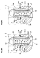
- Fig. 5A to Fig. 5C illustrate an exemplary variation of the first clamping apparatus 11.
- Fig. 5A is a view similar to Fig. 3A .
- Fig. 5B is a section taken along the line 5B-5B of Fig. 5A.
- Fig. 5C is a section taken along the line 5C-5C of Fig. 5A .
- a pipe 55 is arranged between the head portion 54 of the connecting rod 53 and the piston rod 52, and the connecting rod 53 is inserted into the pipe 55.
- the advancing means 45 is composed of a plurality of vertically laminated conical disc springs.
- an outer periphery of an upper half portion of the collet type clamp 33 is covered with a cover tube 58.
- the cover tube 58 prevents foreign matter such as swarf from intruding into the rigid sleeve 21 through the slit 36.
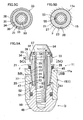
- a positioning mechanism 12a of the second clamping apparatus 12 is different in the following structure from the positioning mechanism 11a of the first clamping apparatus 11.
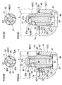
- Fig. 6A is a view similar to Fig. 5A , illustrating a section taken along the line 6A-6A of Fig. 6B.
- Fig. 6B is a section taken along the line 6B-6B of Fig. 6A .
- a pair of protruding portions 80, 80 radially facing each other is provided on the outer periphery of the rigid sleeve 21, and the tapered outer surface 27 is formed on each protruding portion 80.
- the reference number 82 in Fig. 6A and Fig. 6B denotes a rotation stopper pin.
- Fig. 6C illustrates a first exemplary variation of the positioning mechanism 12a.
- a pair of the protruding portions 80, 80 radially facing each other is provided on the inner periphery of the centre hole 20, and the tapered inner surface 23 conforms to each protruding portion 80.
- a pair of the movement-allowing spaces 81, 81 as well is formed in the same way as in Fig. 6B .
- a second exemplary variation of Fig. 6D is that the first exemplary variation of Fig. 6C is modified as follows. Specifically, each of the tapered inner surface 23 and the tapered outer surface 27 is composed of a flat surface instead of a circular surface.
- the third clamping apparatus 13 is different in the following structure from the first clamping apparatus 11 as illustrated in Fig. 7A and Fig. 7B .
- the both peripheral surfaces of the inner peripheral surface of the centre hole 20 and the outer peripheral surface of the rigid sleeve 21 are formed in a vertically straight manner, and an annular gap G for allowing the rigid sleeve 21 to move radially is provided between the both peripheral surfaces.
- a dust seal 46 is installed on an outer periphery of the annular rubber advancing means 45.
- pressurized oil in the lock chamber 63 is discharged and pressurized oil is supplied to the release chamber 66.
- the piston 50 raises the annular clamping member 33 via the connecting rod 53, and the clamping member 33 is changed to be in a diametrically contracted state.
- the rigid sleeve 21 ascends in an advancing strok,e the elastic member 45 being an advancing means, and lightly makes a tapering engagement with the clamping member 33 or faces the clamping member 33 with a slight gap.
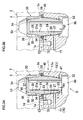
- the work pallet 2 When the work pallet 2 is positioned with respect to the reference block 1, first, as illustrated in Fig. 1 and Fig. 2A (and Fig. 3A ), the work pallet 2 is lowered in the release state mentioned above, and the socket hole 3 is fitted at the outside of the clamping member 33, and the work pallet 2 is received by the flange portion 28 of the rigid sleeve 21. In this state, the seating gap E is formed between the support surfaces 1a and the supported surface 2a. Further, as illustrated in Fig. 3A , the locking gap F is formed between the tapered inner surface 23 and the tapered outer surface 27, and a minute contact gap N1 is formed between an upper end surface of the piston rod 52 and a lower end surface of the rigid sleeve 21.
- the locking gap F is provided as described above, when the socket hole 3 of the work pallet 2 is fitted at the outside of the clamping member 33, it is possible to allow a misalignment between an axis of the socket hole 3 and an axis of the rigid sleeve 21.
- the pressurized oil in the release chamber 66 is discharged and pressurized oil is supplied to the lock chamber 63.
- the piston 50 lowers the clamping member 33 via the connecting rod 53, and the tapered inner peripheral surface 34 of the clamping member 33 makes a wedge-engagement with the tapered outer peripheral surface 30 of the rigid sleeve 21.
- a contact gap N2 greater than the contact gap N1 of Fig. 3A is formed between the upper end surface of the piston rod 52 and the lower end surface of the rigid sleeve 21.
- the clamping member 33 diametrically expands while compressing the elastic member 45 downward via the rigid sleeve 21, the clamping member coming into close contact with the socket hole 3.
- the supported surface 2a of the work pallet 2 comes into contact with the support surfaces 1a of the reference block 1.
- a half-locked state shown in Fig. 4A a descending stroke M1 corresponding to the seating gap E of Fig. 3B is defined above the stopper 47, and a contact gap N3 slightly greater than the contact gap N2 of Fig. 3B is defined between the upper end surface of the piston rod 52 and the lower end surface of the rigid sleeve 21.
- the clamping member 33 moves while sliding downward along the inner peripheral surface of the socket hole 3, and the clamping member 33 further lowers the rigid sleeve 21 while compressing the elastic member 45.
- the rigid sleeve 21 descends by a descending stroke M2 corresponding to the advancing stroke
- the tapered surface 27 of the rigid sleeve 21 makes a tapering engagement with the tapered inner surface 23 of the centre hole 20.
- the rigid sleeve 21 is radially (horizontally) and axially (vertically) constrained by the reference block 1 via the tapering engagement.
- the work pallet 2 is horizontally positioned with respect to the housing 15 via the rigid sleeve 21 in the constrained state and the clamping member 33 in close contact with the socket hole 3.
- the tapered inner peripheral surface 34 of the clamping member 33 makes a strong wedge-engagement with the tapered outer peripheral surface 30 of the rigid sleeve 21 received by the housing 15 and diametrically expands, and the straight outer peripheral surface 35 of the clamping member 33 comes into strong and close contact with the socket hole 3.
- the connecting rod 53 strongly presses the supported surface 2a of the work pallet 2 into close contact with the support surfaces 1a of the reference block 1 via the clamping member 33.
- the support surfaces 1a and the supported surface 2a may be substantially completely in a contact state with each other.
- the clamping member 33 operates as follows. After the clamping member 33 comes into close contact with the socket hole 3, the clamping member 33 descends while sliding along the socket 3. Then, as described above, when the tapered outer surface 27 of the rigid sleeve 21 makes a tapering engagement with the tapered inner surface 23, the clamping member 33 comes into strong and close contact with the socket hole 3, and the clamping member 33 presses the work pallet 2 onto the reference block 1.
- the two third clamping apparatuses 13, 13 with only locking functions firmly fix the work pallet 2 to the reference block 1 via the clamping member 33.
- the pressurized oil in the lock chamber 63 be discharged and pressurized oil be supplied to the release chamber 66.
- the piston 50 raises the clamping member 33 via the connecting rod 53, and the clamping member 33 diametrically contracts due to its own elastic restoring force, the lock state is released.
- the contact gap N1 illustrated in Fig. 3A be eliminated, and that the piston rod 52 forcibly press up the rigid sleeve 21.
- Fig. 8 and Fig. 9A to Fig. 9D respectively illustrate a second embodiment and a third embodiment of the first clamping apparatus 11
- Fig. 8 illustrating the second embodiment is a view similar to Fig. 2A .
- the drive means D is constructed to be a human-powered type.
- the lower portion of the connecting rod 53 is threaded into a screw hole 88 of the base plate 4.
- a hexagonal wrench 90 is inserted into an input hole 89 of the head portion 54 of the connecting rod 53, and the connecting rod 53 is rotated in a clockwise direction in plan view.
- the head portion 54 lowers the clamping member 33 while diametrically expanding the clamping member 33.
- the elastic member (the advancing means) 45 is formed into a lateral U-shape in section.
- the base plate 4 and the housing 15 may be integrally formed, instead of being separately constructed as exemplified.
- the clamping member 33 of the respective embodiments may be a clamping member in which a several cicuferential grooves alternately open in an upper surface and a lower surface of its peripheral wall are circumferentially provided, instead of a clamping member in which one slit 36 is provided in the peripheral wall.
- the clamping member 33 may be composed of a plurality of circumferentially spaced separate bodies.
- the outer surface of the clamping member 33 may be formed in a serrated manner or in an uneven manner, instead of being formed vertically straight.
- the clamping member 33 is not limited to the above-described structures, but other well-known structures may be employed.
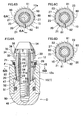
- Fig. 9A to Fig. 9D illustrate a third embodiment of the first clamping apparatus 11.
- Fig. 9A is a cross section corresponding to a section taken along the line 9A-9A of Fig. 9B , illustrating a release state of the clamping apparatus 11.
- Fig. 9B is a section in plan view of Fig. 9A.
- Fig. 9C is a view similar to Fig. 9A , illustrating a lock state of the clamping apparatus.
- Fig. 9D is a section in plan view of Fig. 9C .
- the rigid sleeve 21 includes a top wall 21b. Further, three radially extending through holes 95 are formed at circumferentially spaced intervals in a peripheral wall 25a of the projecting portion 25 of the rigid sleeve 21. Radially moveable balls 96 are inserted into the respective through holes 95. The narrowed outer end portions of the through holes 95 prevent the balls 96 from reaching the outside. The plurality of balls 96 serve as the clamping member 33.
- a vertically extending grove 97 is formed to correspond to the respective balls 96 in the upper portion (leading end portion) of the connecting rod 53 of the output member 48.
- the groove 97 has an output surface 98 and a retreating surface 99.
- the work pallet 2 When the work pallet 2 is positioned with respect to the reference block 1, first, as illustrated in Fig. 9A , the work pallet 2 is lowered in the release state to make the socket holes 3 be disposed at the outside of the plurality of balls 96, and the work pallet 2 is received by the flange portion 28 of the rigid sleeve 21. In this state, the seating gap E is formed between the support surfaces 1a and the supported surface 2a, and the locking gap F is formed between the tapered inner surface 23 and the tapered outer surface 27.
- the output member 48 is lowered. Then, the output surface 98 of the connecting rod 53 pushes the balls 96 towards the outside. Thereby, the balls 96 radiallyoutwardly move in the through holes 95 of the rigid sleeve 21, and the balls 96 come into contact with the socket hole 3.
- the plurality of balls 96 move while sliding downward along the inner peripheral surface of the socket hole 3 (or, while the balls 96 elastically deform or plastically deform the inner peripheral surface of the socket hole 3), and the plurality of balls 96 further lower the rigid sleeve 21 against the elastic member 45, and the tapered outer surface 27 of the rigid sleeve 21 makes a tapering engagement with the tapered inner surface 23 of the centre hole 20.
- the rigid sleeve 21 is radially (horizontally) and axially (vertically) constrained by the reference block 1 via the tapering engagement.
- the work pallet 2 is horizontally positioned with respect to the housing 15 via the rigid sleeve 21 in the constrained state and the plurality of balls 96 in a close contact state with the socket hole 3.
- the output member 48 is driven to further descend with respect to the rigid sleeve 21
- the plurality of balls 96 come into strong and close contact with the socket hole 3.
- the connecting rod 53 strongly presses the supported surface 2a of the work pallet 2 into close contact with the support surfaces 1a of the reference block 1 via the plurality of balls 96.
- the numbers of the through holes 95 and the balls 96 to be installed may be respectively two, or four or more, instead of three.
- Three or more tapered inner surfaces 23 of the centre hole 20 may be provided, instead of providing vertically two or one thereof.
- the tapered inner surface 23 of the centre hole 20 and the tapered outer surface 27 of the rigid sleeve 21 are preferably circular tapered surfaces in section. However, instead thereof, those may be elliptical tapered surfaces, or may be a plurality of sloping wedge surfaces arranged circumferentially at predetermined intervals. In this case, a plurality of inclined grooves may be arranged circumferentially at predetermined intervals in the tapered inner surface 23 and the tapered outer surface 27, and each wedge surface may be composed of a bottom wall of each inclined groove.
- the advancing means 45 may be any means to press the rigid sleeve 21 upward (towards the leading end). Accordingly, the advancing means 45 may be attached between a lower portion of the rigid sleeve 21 and the housing 15, instead of being attached between the flange portion 28 of the rigid sleeve 21 and the housing 15. Further, the advancing means 45 may utilize a combination of pressurized fluid such as compressed air or pressurized oil and a piston, instead of or in addition to the exemplified elastic member such as rubber and a spring such as a coned disc spring.
- pressurized fluid such as compressed air or pressurized oil
- a piston instead of or in addition to the exemplified elastic member such as rubber and a spring such as a coned disc spring.
- cleaning means are provided for the respective clamping apparatuses 11, 12, and 13. Contact portions between the support surfaces 1a and the supported surface 2a, a fitting portion between the socket hole 3 and the clamping member 33, fitting portions between the balls 96 and the through holes 95, and respective fitting surfaces between the tapered inner surfaces 23 and the tapered outer surface 27 are cleaned by pressurized fluid such as compressed air.
- pressurized fluid such as compressed air.
- only one clamping apparatus 13 with only a locking functions may be installed, instead of the exemplified two.
- the clamping apparatus 13 is not limited to the exemplified structure, and may be another type of clamp.
- each of the clamping apparatuses 11, 12, and 13 may be a spring locking and hydraulic releasing type or a hydraulic locking and spring releasing type, instead of the exemplified hydraulic double-acting type.
- Pressurized fluid used for locking or releasing may be gas such as compressed air, instead of the exemplified pressurized oil.
- pressurized fluid for cleaning may be a gas such as nitrogen or liquid, instead of the exemplified compressed air.
- the first clamping apparatus 11 may be installed in plural number
- the second clamping apparatus 12 may be installed in plural number.
- any one of both of the first clamping apparatus 11 and the second clamping apparatus 12 may be installed in plural number.
- the direction in which a plurality of the clamping apparatus are arranged may be circular or straight.
- the support surface 1a may be provided on the base plate 4, instead of being provided on the upper surface of each boss 72 of the housing 15. Further, the housing 15 and the base plate 4 may be integrally formed, instead of being separately formed.
- the combination of the reference block and the movable block may be a combination of a table of a machine tool and a work pallet, a combination of a work pallet and a jig base, a combination of a jig base and a work piece, or a combination of a working jig such as a welding jig and a working article such as a work piece, instead of the exemplified combination of the base plate 4 and the work pallet 2.
- the present invention is applicable to the positioning of a work piece, a tool and the like used in various processing machines such as a laser processing machine and an electric discharge processing machine. Further, it is a matter of course that a clamping apparatus of the present invention can be used singly instead of in a plurality.
Landscapes
- Engineering & Computer Science (AREA)
- Mechanical Engineering (AREA)
- Jigs For Machine Tools (AREA)
- Load-Engaging Elements For Cranes (AREA)
- Vehicle Body Suspensions (AREA)
- Application Of Or Painting With Fluid Materials (AREA)
Claims (13)
- Klemmvorrichtung, die einen beweglichen Block (2) mit einem Hülsenloch (3) an einen Bezugsblock (1) klemmt und die aufweist:ein zentrales Loch (20), das im Bezugsblock (1) so vorgesehen ist, dass es dem Hülsenloch (3) zugewandt ist;eine starre Hülse (21), die durch den Bezugsblock (1) axial beweglich innerhalb eines vorbestimmten Bereichs abgestützt ist und ein sich axial erstreckendes zylindrisches Loch (21a) aufweist, wobei ein Teil (25) der Hülse (21) weiter in Richtung eines Vorderendes vorsteht als das zentrale Loch (20) und in das Hülsenloch (3) eingesetzt wird;ein Ausführungselement (48), das in das zylindrische Loch (21a) der starren Hülse (21) eingesetzt ist, wobei das Ausführungselement (48) mit einem Klemmelement (33) verbunden ist, das so angeordnet ist, dass es in das Hülsenloch (3) eingesetzt wird;ein Vorschubmittel (45) zum Pressen der starren Hülse (21) in Richtung des Vorderendes; undein Antriebsmittel (D) zum Bewegen des Ausführungselements (48) in Richtung eines Basisendes; wobei das Ausführungselement (48) das Klemmelement (33) gegen das Vorschubmittel (45) in Richtung des Basisendes und radial nach außen zur Verriegelung bewegt;dadurch gekennzeichnet, dass
das Klemmelement (33) am vorstehenden Teil (25) der Hülse (21) vorgesehen ist;
das zentrale Loch (20) eine verjüngte Innenfläche (23) aufweist, die sich in Richtung des Basisendes verschmälert;
die starre Hülse (21) eine verjüngte Außenfläche (27) aufweist, die einen Verjüngungseingriff mit der verjüngten Innenfläche (23) des zentralen Lochs (20) herstellt,
und das Ausführungselement (48) veranlasst, dass die verjüngte Außenfläche (27) der starren Hülse (21) einen Verjüngungseingriff mit der verjüngten Innenfläche (23) des zentralen Lochs (20) ausbildet. - Klemmvorrichtung nach Anspruch 1, wobei
ein Flanschteil (28) von der starren Hülse (21) außerhalb des zentralen Lochs (20) radial nach außen vorsteht und das Vorschubmittel (45) zwischen dem Flanschteil (28) und dem Bezugsblock (1) angeordnet ist. - Klemmvorrichtung nach Anspruch 2, wobei
das Vorschubmittel (45) aus einem ringförmigen elastischen Element besteht. - Klemmvorrichtung nach Anspruch 1, wobei
ein Flanschteil (28) von der starren Hülse (21) außerhalb des zentralen Lochs (20) radial nach außen vorsteht, und in einem Zustand, in dem der bewegliche Block (2) am Flanschteil (28) angeordnet ist, das Vorschubmittel (45) den beweglichen Block (2) presst, um einen Sitzspalt (E) zwischen einer abgestützten Oberfläche (2a) des beweglichen Blocks (2) und einer Stützoberfläche (1a) des Bezugsblocks (1) zu bilden, und ein Erfassungsloch (74) für Druckfluid für die Sitzbestätigung in der Stützoberfläche (1a) vorgesehen ist. - Klemmvorrichtung nach Anspruch 1, wobei
ein Zuführungskanal (76) für Druckfluid für die Verriegelungsbestätigung im Bezugsblock (1) vorgesehen ist, der Zuführungskanal (76) in Verbindung mit einem Außenraum über einen Verriegelungsspalt (F) zwischen der verjüngten Innenfläche (23) und der verjüngten Außenfläche (27) steht, und die kommunikative Verbindung zwischen dem Zuführungskanal (76) und dem Außenraum abgesperrt wird, wenn die verjüngte Außenfläche (27) einen Verjüngungseingriff mit der verjüngten Innenfläche (23) herstellt. - Klemmvorrichtung nach einem der Ansprüche 1 bis 5, wobei die verjüngte Außenfläche (27) der starren Hülse (21) einen Verjüngungseingriff mit im Wesentlichen dem ganzen Umfang der verjüngten Innenfläche (23) des zentralen Lochs (20) herstellt, das im Bezugsblock (1) vorgesehen ist.
- Klemmvorrichtung nach einem der Ansprüche 1 bis 5, wobei ein Paar von vorstehenden Teilen (80, 80), die radial einander gegenüberliegen, an mindestens einem inneren Umfang des zentralen Lochs (20), das im Bezugsblock (1) vorgesehen ist, oder einem äußeren Umfang der starren Hülse (21) vorgesehen ist, und die verjüngte Innenfläche (23) oder die verjüngte Außenfläche (27) zu den jeweiligen vorstehenden Teilen (80) ausgebildet ist, und eine Bewegung zulassende Räume (81, 81), die durch die vorstehenden Teile (80, 80) unterteilt sind, so ausgebildet sind, dass sie zwischen dem inneren Umfang des zentralen Lochs (20) und dem äußeren Umfang der starren Hülse (21) radial einander gegenüberliegen.
- Klemmvorrichtung nach einem der Ansprüche 1 bis 5, wobei das Klemmelement (33) aus einer diametral ausdehnbaren und diametral zusammenziehbaren Klemmhülse besteht und die Klemmhülse (33) einen Keileingriff mit dem vorstehenden Teil (25) der starren Hülse (21) von der Vorderendseite aus herstellt.
- Klemmvorrichtung nach einem der Ansprüche 1 bis 5, wobei das Klemmelement (33) aus einer Vielzahl von Kugeln (96) besteht, die an einer Umfangswand des vorstehenden Teils (25) der starren Hülse (21) in Intervallen peripherisch angeordnet sind, und das Ausführungselement (48) die jeweiligen Kugeln (96) in radial äußere Eingriffspositionen (X) umstellt.
- Klemmvorrichtung nach Anspruch 9, wobei mindestens drei Kugeln (96) vorhanden sind.
- Klemmsystem mit mindestens einer Klemmvorrichtung nach einem der Ansprüche 1 bis 5.
- Klemmsystem mit einer Klemmvorrichtung nach Anspruch 6 und einer Klemmvorrichtung nach Anspruch 7.
- Klemmsystem mit mindestens zwei der Klemmvorrichtung nach Anspruch 7.
Applications Claiming Priority (2)
| Application Number | Priority Date | Filing Date | Title |
|---|---|---|---|
| JP2005376357 | 2005-11-28 | ||
| PCT/JP2006/323309 WO2007060986A1 (ja) | 2005-11-28 | 2006-11-22 | クランプ装置およびその装置を利用したクランピングシステム |
Publications (3)
| Publication Number | Publication Date |
|---|---|
| EP1961516A1 EP1961516A1 (de) | 2008-08-27 |
| EP1961516A4 EP1961516A4 (de) | 2009-06-10 |
| EP1961516B1 true EP1961516B1 (de) | 2010-03-31 |
Family
ID=38067211
Family Applications (1)
| Application Number | Title | Priority Date | Filing Date |
|---|---|---|---|
| EP06833131A Not-in-force EP1961516B1 (de) | 2005-11-28 | 2006-11-22 | Klemmvorrichtung und solch eine vorrichtung verwendendes klemmsystem |
Country Status (8)
| Country | Link |
|---|---|
| US (1) | US20090315239A1 (de) |
| EP (1) | EP1961516B1 (de) |
| JP (1) | JP4896889B2 (de) |
| KR (1) | KR20080072907A (de) |
| CN (1) | CN100563920C (de) |
| AT (1) | ATE462530T1 (de) |
| DE (1) | DE602006013349D1 (de) |
| WO (1) | WO2007060986A1 (de) |
Cited By (1)
| Publication number | Priority date | Publication date | Assignee | Title |
|---|---|---|---|---|
| CN102059562A (zh) * | 2010-11-15 | 2011-05-18 | 吴江市菀坪镙丝厂 | 柱体件夹具 |
Families Citing this family (28)
| Publication number | Priority date | Publication date | Assignee | Title |
|---|---|---|---|---|
| JP5184505B2 (ja) * | 2007-02-23 | 2013-04-17 | 株式会社コスメック | クランプの動作検出装置 |
| JP4297511B1 (ja) | 2008-02-15 | 2009-07-15 | パスカルエンジニアリング株式会社 | クランプ装置 |
| JP4302174B1 (ja) * | 2008-02-15 | 2009-07-22 | パスカルエンジニアリング株式会社 | クランプ装置 |
| JP5346542B2 (ja) | 2008-04-24 | 2013-11-20 | パスカルエンジニアリング株式会社 | クランプ装置 |
| JP5435908B2 (ja) * | 2008-08-06 | 2014-03-05 | パスカルエンジニアリング株式会社 | クランプ装置 |
| JP2010099785A (ja) * | 2008-10-24 | 2010-05-06 | Pascal Engineering Corp | ワークパレット位置決め固定機構 |
| JP5276519B2 (ja) * | 2009-05-26 | 2013-08-28 | 株式会社神戸製鋼所 | クランプ装置 |
| JP5385710B2 (ja) * | 2009-07-09 | 2014-01-08 | パスカルエンジニアリング株式会社 | クランプ装置 |
| JP5674191B2 (ja) * | 2010-03-01 | 2015-02-25 | パスカルエンジニアリング株式会社 | クランプ装置 |
| JP2012040674A (ja) * | 2010-08-23 | 2012-03-01 | Mitsubishi Heavy Ind Ltd | クランパ、水室内作業装置およびクランプ方法 |
| JP2012042185A (ja) | 2010-08-23 | 2012-03-01 | Mitsubishi Heavy Ind Ltd | クランパおよび水室内作業装置 |
| CN101954607B (zh) * | 2010-08-30 | 2011-12-14 | 常州市第八纺织机械有限公司 | 针芯床连杆架钻夹具 |
| CN102756561B (zh) * | 2011-04-29 | 2014-12-03 | 金宝电子工业股份有限公司 | 流体检测治具 |
| CN102248413A (zh) * | 2011-07-19 | 2011-11-23 | 重庆市蓝黛实业有限公司 | 拉键槽夹具 |
| CN102357448B (zh) * | 2011-08-31 | 2013-03-27 | 奇瑞汽车股份有限公司 | 一种可自动检测工件规格的工件固定装置 |
| JP5996306B2 (ja) * | 2012-07-04 | 2016-09-21 | パスカルエンジニアリング株式会社 | 物体位置決め固定装置 |
| ITTV20120129A1 (it) * | 2012-07-11 | 2014-01-12 | Almerino Canuto | Dispositivo di compensazione del disassamento in sistemi di bloccaggio automatici |
| CN104209891B (zh) * | 2013-05-31 | 2016-12-28 | 富泰华工业(深圳)有限公司 | 定位机构及其采用的胀紧组件 |
| DE102013222089A1 (de) * | 2013-10-30 | 2015-04-30 | Trumpf Sachsen Gmbh | Kupplungsvorrichtung und Kupplungsanordnung zum Verbinden zweier Bauteile einer maschinellen Anordnung für die Werkstückbearbeitung, insbesondere für die Blechbearbeitung |
| FR3017556B1 (fr) * | 2014-02-14 | 2016-09-16 | Snecma | Systeme de bridage de piece et procede d'etanchage de la virole interieure d'un redresseur basse pression de turbomachine |
| CN105436910A (zh) * | 2015-06-12 | 2016-03-30 | 新兴重工湖北三六一一机械有限公司 | 一种夹具快速更换装置 |
| TWI609745B (zh) * | 2015-07-02 | 2018-01-01 | 嘉新精密有限公司 | 側向夾持的彈性定位塊結構 |
| JP6683472B2 (ja) * | 2015-11-30 | 2020-04-22 | 株式会社コスメック | クランプ装置 |
| ITUB20160781A1 (it) * | 2016-01-27 | 2017-07-27 | Hydroblock S R L | Dispositivo per il bloccaggio di pezzi su macchine utensili |
| CN107127694A (zh) * | 2017-06-01 | 2017-09-05 | 广西汽车集团有限公司 | 一种螺纹工件夹紧工装 |
| CN109128894B (zh) * | 2017-06-28 | 2024-03-19 | 杨斌堂 | 管卡紧机构 |
| CN110524269A (zh) * | 2019-08-20 | 2019-12-03 | 浙江吉孚汽车传动系统有限公司 | 行星架加工用夹具 |
| CN110509070B (zh) * | 2019-08-30 | 2020-07-03 | 北京智同精密传动科技有限责任公司 | 行星架偏心加工工装及其加工工艺 |
Family Cites Families (8)
| Publication number | Priority date | Publication date | Assignee | Title |
|---|---|---|---|---|
| JPH01170532A (ja) * | 1987-12-25 | 1989-07-05 | Kosumetsuku:Kk | シリンダ形油圧クランプ |
| JP3550010B2 (ja) * | 1997-12-24 | 2004-08-04 | 株式会社コスメック | クランプ装置 |
| JP3663479B2 (ja) * | 1998-10-07 | 2005-06-22 | オークマ株式会社 | 工作機械の工作物位置決め用治具 |
| JP3338669B2 (ja) * | 1999-08-03 | 2002-10-28 | 株式会社コスメック | データム機能付きクランプ装置 |
| US7232121B2 (en) * | 2002-08-06 | 2007-06-19 | Kosmek Ltd. | Clamping device |
| CN1744964B (zh) | 2003-01-29 | 2010-04-14 | 克斯美库股份有限公司 | 夹持装置及使用该夹持装置的夹持系统 |
| KR20060037336A (ko) * | 2003-07-25 | 2006-05-03 | 가부시키가이샤 코스멕 | 클램프 장치 |
| JP4607635B2 (ja) * | 2005-02-23 | 2011-01-05 | 株式会社コスメック | クランプ装置およびその装置を利用したクランピングシステム |
-
2006
- 2006-11-22 JP JP2007546465A patent/JP4896889B2/ja not_active Expired - Fee Related
- 2006-11-22 EP EP06833131A patent/EP1961516B1/de not_active Not-in-force
- 2006-11-22 US US12/084,954 patent/US20090315239A1/en not_active Abandoned
- 2006-11-22 AT AT06833131T patent/ATE462530T1/de not_active IP Right Cessation
- 2006-11-22 CN CNB2006800442725A patent/CN100563920C/zh not_active Expired - Fee Related
- 2006-11-22 KR KR1020087013919A patent/KR20080072907A/ko not_active Withdrawn
- 2006-11-22 WO PCT/JP2006/323309 patent/WO2007060986A1/ja not_active Ceased
- 2006-11-22 DE DE602006013349T patent/DE602006013349D1/de active Active
Cited By (1)
| Publication number | Priority date | Publication date | Assignee | Title |
|---|---|---|---|---|
| CN102059562A (zh) * | 2010-11-15 | 2011-05-18 | 吴江市菀坪镙丝厂 | 柱体件夹具 |
Also Published As
| Publication number | Publication date |
|---|---|
| WO2007060986A1 (ja) | 2007-05-31 |
| KR20080072907A (ko) | 2008-08-07 |
| JPWO2007060986A1 (ja) | 2009-05-07 |
| EP1961516A1 (de) | 2008-08-27 |
| JP4896889B2 (ja) | 2012-03-14 |
| ATE462530T1 (de) | 2010-04-15 |
| CN100563920C (zh) | 2009-12-02 |
| EP1961516A4 (de) | 2009-06-10 |
| CN101316678A (zh) | 2008-12-03 |
| DE602006013349D1 (de) | 2010-05-12 |
| US20090315239A1 (en) | 2009-12-24 |
Similar Documents
| Publication | Publication Date | Title |
|---|---|---|
| EP1961516B1 (de) | Klemmvorrichtung und solch eine vorrichtung verwendendes klemmsystem | |
| US7303186B2 (en) | Aligning drive mechanism and positioning apparatus having this mechanism | |
| EP1598144B1 (de) | Klemmvorrichtung und klemmsystem damit | |
| EP1078713B1 (de) | Spannvorrichtung mit Ausrichtfunktion | |
| US7168695B2 (en) | Positioning device | |
| CN102574254B (zh) | 固紧装置 | |
| CN1263582C (zh) | 自动定位装置 | |
| KR20110041546A (ko) | 클램프 장치 | |
| CN1411952A (zh) | 夹持设备 | |
| EP1649973B1 (de) | Klemmvorrichtung | |
| CN100486761C (zh) | 定位装置和具有该定位装置的夹持系统 | |
| EP1671743B1 (de) | Positioniervorrichtung und klemmsystem mit der vorrichtung | |
| JP4954899B2 (ja) | 位置決め装置および位置決めシステム | |
| US20060289709A1 (en) | Positioning device and clamping system having the same | |
| US7377505B2 (en) | Clamping apparatus and clamping system | |
| JP2003181730A (ja) | クランプ装置 | |
| JP4607635B2 (ja) | クランプ装置およびその装置を利用したクランピングシステム | |
| JPH11245130A (ja) | クランプ装置 | |
| JP2025082134A (ja) | 倍力機構付きシリンダ装置 |
Legal Events
| Date | Code | Title | Description |
|---|---|---|---|
| PUAI | Public reference made under article 153(3) epc to a published international application that has entered the european phase |
Free format text: ORIGINAL CODE: 0009012 |
|
| 17P | Request for examination filed |
Effective date: 20080627 |
|
| AK | Designated contracting states |
Kind code of ref document: A1 Designated state(s): AT BE BG CH CY CZ DE DK EE ES FI FR GB GR HU IE IS IT LI LT LU LV MC NL PL PT RO SE SI SK TR |
|
| A4 | Supplementary search report drawn up and despatched |
Effective date: 20090511 |
|
| 17Q | First examination report despatched |
Effective date: 20090619 |
|
| GRAP | Despatch of communication of intention to grant a patent |
Free format text: ORIGINAL CODE: EPIDOSNIGR1 |
|
| GRAS | Grant fee paid |
Free format text: ORIGINAL CODE: EPIDOSNIGR3 |
|
| GRAA | (expected) grant |
Free format text: ORIGINAL CODE: 0009210 |
|
| AK | Designated contracting states |
Kind code of ref document: B1 Designated state(s): AT BE BG CH CY CZ DE DK EE ES FI FR GB GR HU IE IS IT LI LT LU LV MC NL PL PT RO SE SI SK TR |
|
| REG | Reference to a national code |
Ref country code: GB Ref legal event code: FG4D Ref country code: CH Ref legal event code: EP |
|
| REG | Reference to a national code |
Ref country code: IE Ref legal event code: FG4D |
|
| REF | Corresponds to: |
Ref document number: 602006013349 Country of ref document: DE Date of ref document: 20100512 Kind code of ref document: P |
|
| REG | Reference to a national code |
Ref country code: NL Ref legal event code: VDEP Effective date: 20100331 |
|
| PG25 | Lapsed in a contracting state [announced via postgrant information from national office to epo] |
Ref country code: LT Free format text: LAPSE BECAUSE OF FAILURE TO SUBMIT A TRANSLATION OF THE DESCRIPTION OR TO PAY THE FEE WITHIN THE PRESCRIBED TIME-LIMIT Effective date: 20100331 |
|
| LTIE | Lt: invalidation of european patent or patent extension |
Effective date: 20100331 |
|
| PG25 | Lapsed in a contracting state [announced via postgrant information from national office to epo] |
Ref country code: SI Free format text: LAPSE BECAUSE OF FAILURE TO SUBMIT A TRANSLATION OF THE DESCRIPTION OR TO PAY THE FEE WITHIN THE PRESCRIBED TIME-LIMIT Effective date: 20100331 Ref country code: AT Free format text: LAPSE BECAUSE OF FAILURE TO SUBMIT A TRANSLATION OF THE DESCRIPTION OR TO PAY THE FEE WITHIN THE PRESCRIBED TIME-LIMIT Effective date: 20100331 Ref country code: FI Free format text: LAPSE BECAUSE OF FAILURE TO SUBMIT A TRANSLATION OF THE DESCRIPTION OR TO PAY THE FEE WITHIN THE PRESCRIBED TIME-LIMIT Effective date: 20100331 Ref country code: LV Free format text: LAPSE BECAUSE OF FAILURE TO SUBMIT A TRANSLATION OF THE DESCRIPTION OR TO PAY THE FEE WITHIN THE PRESCRIBED TIME-LIMIT Effective date: 20100331 Ref country code: PL Free format text: LAPSE BECAUSE OF FAILURE TO SUBMIT A TRANSLATION OF THE DESCRIPTION OR TO PAY THE FEE WITHIN THE PRESCRIBED TIME-LIMIT Effective date: 20100331 |
|
| PG25 | Lapsed in a contracting state [announced via postgrant information from national office to epo] |
Ref country code: CY Free format text: LAPSE BECAUSE OF FAILURE TO SUBMIT A TRANSLATION OF THE DESCRIPTION OR TO PAY THE FEE WITHIN THE PRESCRIBED TIME-LIMIT Effective date: 20100331 Ref country code: BE Free format text: LAPSE BECAUSE OF FAILURE TO SUBMIT A TRANSLATION OF THE DESCRIPTION OR TO PAY THE FEE WITHIN THE PRESCRIBED TIME-LIMIT Effective date: 20100331 Ref country code: EE Free format text: LAPSE BECAUSE OF FAILURE TO SUBMIT A TRANSLATION OF THE DESCRIPTION OR TO PAY THE FEE WITHIN THE PRESCRIBED TIME-LIMIT Effective date: 20100331 Ref country code: SE Free format text: LAPSE BECAUSE OF FAILURE TO SUBMIT A TRANSLATION OF THE DESCRIPTION OR TO PAY THE FEE WITHIN THE PRESCRIBED TIME-LIMIT Effective date: 20100331 Ref country code: RO Free format text: LAPSE BECAUSE OF FAILURE TO SUBMIT A TRANSLATION OF THE DESCRIPTION OR TO PAY THE FEE WITHIN THE PRESCRIBED TIME-LIMIT Effective date: 20100331 Ref country code: NL Free format text: LAPSE BECAUSE OF FAILURE TO SUBMIT A TRANSLATION OF THE DESCRIPTION OR TO PAY THE FEE WITHIN THE PRESCRIBED TIME-LIMIT Effective date: 20100331 Ref country code: ES Free format text: LAPSE BECAUSE OF FAILURE TO SUBMIT A TRANSLATION OF THE DESCRIPTION OR TO PAY THE FEE WITHIN THE PRESCRIBED TIME-LIMIT Effective date: 20100712 |
|
| PG25 | Lapsed in a contracting state [announced via postgrant information from national office to epo] |
Ref country code: CZ Free format text: LAPSE BECAUSE OF FAILURE TO SUBMIT A TRANSLATION OF THE DESCRIPTION OR TO PAY THE FEE WITHIN THE PRESCRIBED TIME-LIMIT Effective date: 20100331 Ref country code: SK Free format text: LAPSE BECAUSE OF FAILURE TO SUBMIT A TRANSLATION OF THE DESCRIPTION OR TO PAY THE FEE WITHIN THE PRESCRIBED TIME-LIMIT Effective date: 20100331 Ref country code: IS Free format text: LAPSE BECAUSE OF FAILURE TO SUBMIT A TRANSLATION OF THE DESCRIPTION OR TO PAY THE FEE WITHIN THE PRESCRIBED TIME-LIMIT Effective date: 20100731 |
|
| PG25 | Lapsed in a contracting state [announced via postgrant information from national office to epo] |
Ref country code: DK Free format text: LAPSE BECAUSE OF FAILURE TO SUBMIT A TRANSLATION OF THE DESCRIPTION OR TO PAY THE FEE WITHIN THE PRESCRIBED TIME-LIMIT Effective date: 20100331 Ref country code: PT Free format text: LAPSE BECAUSE OF FAILURE TO SUBMIT A TRANSLATION OF THE DESCRIPTION OR TO PAY THE FEE WITHIN THE PRESCRIBED TIME-LIMIT Effective date: 20100802 |
|
| PGFP | Annual fee paid to national office [announced via postgrant information from national office to epo] |
Ref country code: FR Payment date: 20101125 Year of fee payment: 5 |
|
| PLBE | No opposition filed within time limit |
Free format text: ORIGINAL CODE: 0009261 |
|
| STAA | Information on the status of an ep patent application or granted ep patent |
Free format text: STATUS: NO OPPOSITION FILED WITHIN TIME LIMIT |
|
| 26N | No opposition filed |
Effective date: 20110104 |
|
| PG25 | Lapsed in a contracting state [announced via postgrant information from national office to epo] |
Ref country code: IT Free format text: LAPSE BECAUSE OF FAILURE TO SUBMIT A TRANSLATION OF THE DESCRIPTION OR TO PAY THE FEE WITHIN THE PRESCRIBED TIME-LIMIT Effective date: 20100331 |
|
| PGFP | Annual fee paid to national office [announced via postgrant information from national office to epo] |
Ref country code: DE Payment date: 20101130 Year of fee payment: 5 |
|
| PG25 | Lapsed in a contracting state [announced via postgrant information from national office to epo] |
Ref country code: MC Free format text: LAPSE BECAUSE OF NON-PAYMENT OF DUE FEES Effective date: 20101130 |
|
| REG | Reference to a national code |
Ref country code: CH Ref legal event code: PL |
|
| GBPC | Gb: european patent ceased through non-payment of renewal fee |
Effective date: 20101122 |
|
| PG25 | Lapsed in a contracting state [announced via postgrant information from national office to epo] |
Ref country code: CH Free format text: LAPSE BECAUSE OF NON-PAYMENT OF DUE FEES Effective date: 20101130 Ref country code: LI Free format text: LAPSE BECAUSE OF NON-PAYMENT OF DUE FEES Effective date: 20101130 |
|
| PG25 | Lapsed in a contracting state [announced via postgrant information from national office to epo] |
Ref country code: IE Free format text: LAPSE BECAUSE OF NON-PAYMENT OF DUE FEES Effective date: 20101122 |
|
| PG25 | Lapsed in a contracting state [announced via postgrant information from national office to epo] |
Ref country code: GB Free format text: LAPSE BECAUSE OF NON-PAYMENT OF DUE FEES Effective date: 20101122 |
|
| REG | Reference to a national code |
Ref country code: FR Ref legal event code: ST Effective date: 20120731 |
|
| REG | Reference to a national code |
Ref country code: DE Ref legal event code: R119 Ref document number: 602006013349 Country of ref document: DE Effective date: 20120601 |
|
| PG25 | Lapsed in a contracting state [announced via postgrant information from national office to epo] |
Ref country code: LU Free format text: LAPSE BECAUSE OF NON-PAYMENT OF DUE FEES Effective date: 20101122 Ref country code: BG Free format text: LAPSE BECAUSE OF FAILURE TO SUBMIT A TRANSLATION OF THE DESCRIPTION OR TO PAY THE FEE WITHIN THE PRESCRIBED TIME-LIMIT Effective date: 20100331 Ref country code: HU Free format text: LAPSE BECAUSE OF FAILURE TO SUBMIT A TRANSLATION OF THE DESCRIPTION OR TO PAY THE FEE WITHIN THE PRESCRIBED TIME-LIMIT Effective date: 20101001 |
|
| PG25 | Lapsed in a contracting state [announced via postgrant information from national office to epo] |
Ref country code: TR Free format text: LAPSE BECAUSE OF FAILURE TO SUBMIT A TRANSLATION OF THE DESCRIPTION OR TO PAY THE FEE WITHIN THE PRESCRIBED TIME-LIMIT Effective date: 20100331 |
|
| PG25 | Lapsed in a contracting state [announced via postgrant information from national office to epo] |
Ref country code: FR Free format text: LAPSE BECAUSE OF NON-PAYMENT OF DUE FEES Effective date: 20111130 |
|
| PG25 | Lapsed in a contracting state [announced via postgrant information from national office to epo] |
Ref country code: DE Free format text: LAPSE BECAUSE OF NON-PAYMENT OF DUE FEES Effective date: 20120601 |
|
| PG25 | Lapsed in a contracting state [announced via postgrant information from national office to epo] |
Ref country code: BG Free format text: LAPSE BECAUSE OF FAILURE TO SUBMIT A TRANSLATION OF THE DESCRIPTION OR TO PAY THE FEE WITHIN THE PRESCRIBED TIME-LIMIT Effective date: 20100630 |
|
| PG25 | Lapsed in a contracting state [announced via postgrant information from national office to epo] |
Ref country code: GR Free format text: LAPSE BECAUSE OF FAILURE TO SUBMIT A TRANSLATION OF THE DESCRIPTION OR TO PAY THE FEE WITHIN THE PRESCRIBED TIME-LIMIT Effective date: 20100331 |