EP1961568A2 - Einklemmen und Lösen flexibler Platten in einen bzw. aus einem Bildgebungszylinder - Google Patents
Einklemmen und Lösen flexibler Platten in einen bzw. aus einem Bildgebungszylinder Download PDFInfo
- Publication number
- EP1961568A2 EP1961568A2 EP08075125A EP08075125A EP1961568A2 EP 1961568 A2 EP1961568 A2 EP 1961568A2 EP 08075125 A EP08075125 A EP 08075125A EP 08075125 A EP08075125 A EP 08075125A EP 1961568 A2 EP1961568 A2 EP 1961568A2
- Authority
- EP
- European Patent Office
- Prior art keywords
- cylinder
- clamping
- clamping element
- plate
- gap
- Prior art date
- Legal status (The legal status is an assumption and is not a legal conclusion. Google has not performed a legal analysis and makes no representation as to the accuracy of the status listed.)
- Granted
Links
Images



Classifications
-
- B—PERFORMING OPERATIONS; TRANSPORTING
- B41—PRINTING; LINING MACHINES; TYPEWRITERS; STAMPS
- B41F—PRINTING MACHINES OR PRESSES
- B41F27/00—Devices for attaching printing elements or formes to supports
- B41F27/12—Devices for attaching printing elements or formes to supports for attaching flexible printing formes
- B41F27/1262—Devices for attaching printing elements or formes to supports for attaching flexible printing formes without tensioning means
-
- B—PERFORMING OPERATIONS; TRANSPORTING
- B41—PRINTING; LINING MACHINES; TYPEWRITERS; STAMPS
- B41F—PRINTING MACHINES OR PRESSES
- B41F27/00—Devices for attaching printing elements or formes to supports
- B41F27/02—Magnetic devices
Definitions
- the present disclosure relates generally to imaging to produce printing plates, and in particular to a clamping and releasing method, and an apparatus to clamp and release flexible printing plates of different formats and thicknesses.
- Flexographic plates are frequently exposed from computer data using computer-to-plate (CTP, C2P) imaging. Mounting such plates on a cylinder, e.g., the cylinder or imaging cylinder of an external imaging cylinder imaging device is recognized as a problem.
- CTP computer-to-plate
- a flexographic plate on a cylinder is to fix the plates with adhesive tape at the edges. More modem methods use a clamping bar, which clamps the top and bottom edge of a full-size flexographic plate onto the cylinder. The first adhesive tape method is very time consuming and the second method using a clamping bar only works with full format plates. Since flexographic plate material is relatively expensive a modem method to mount partial plates on a full format cylinder are becoming more and more important.
- An example of an external imaging cylinder imaging device for which such a method and apparatus is applicable is the Esko-Graphics Cyrel Digital Imager (CDI) made by Esko-Graphics A/S, Ballerup, Denmark, the applicant of the present invention.
- CDI Esko-Graphics Cyrel Digital Imager
- U.S. Patent 7,165,492 to Koberg, et al. titled METHOD AND APPARATUS TO CLAMP AND RELEASE FLEXIBLE PLATES ON TO AN IMAGING CYLINDER (issued on January, 23, 2007) describes a clamping device, a cylinder including a clamping device, and a method for clamping a plate onto the outer surface of the cylinder.
- the clamping device includes a base body extending in the axial direction and fixed to, or incorporated into the cylinder.
- the clamping device also includes a clamping element extending in the axial direction.
- the clamping device also includes a lifting element located in the interior of the base body and coupled to the clamping element by at least one guiding shaft.
- the lifting element is movable in a first radial direction to move the clamping element away from the outer surface of the cylinder to form a gap between the outer surface and the clamping element.
- the lifting element also is movable in the radial direction opposite the first radial direction to close the gap formed between the outer surface of the cylinder and the clamping element.
- the clamping device also includes a mechanism to impart and maintain compressive force between the clamping element and the outer surface of the cylinder such that any gap formed is maintained closed unless forcibly opened.
- the apparatus is arranged such that when the gap is formed by moving the lifting element in the first radial direction, the edge of a flexible plate can be placed in the gap, and such that when the gap is closed, the plate is maintained clamped onto the outer edge of the cylinder.
- a full-format plate is meant a plate that covers the whole imaging area of the cylinder.
- a partial-format plate is meant a plate that covers part of the overall imaging area, such that several partial-format plates (also called plate segments) may be combined to cover the whole imaging area.
- One prior art method is for a machine operator to manually mount a full-format plate or partial-format plates onto a cylinder with adhesive tape.
- Such a method is used, for example, by external imaging cylinder imaging machines such as the ThermoFlexTM product line made by CREO Inc. of Burnaby, BC, Canada.
- external imaging cylinder imaging machines such as the ThermoFlexTM product line made by CREO Inc. of Burnaby, BC, Canada.
- the operator first mounts a first edge of the plate on the cylinder, fixes it with adhesive tape, turns the cylinder around so that the plate covers the cylinder, and then tapes all the rest of the edges of the plate.
- Another prior art solution is for the machine operator to mount full-format plates-those that fully cover the circumference of a cylinder -with the use of a clamp, which is activated manually.
- An example of a device for so mounting full-format plates is a device used with an imaging cylinder, called EasyClampTM, made by Esko-Graphics A/S, Ballerup, Denmark, the applicant of the present invention. If partial-format plates are used, the machine operator first mounts partial-format plates onto the cylinder with the use of adhesive tape. The mounting by use of adhesive tape, as stated above, is time consuming.
- the terminal strip is only for full-format plates.
- the machine operator mounts partial-format plates with the use of adhesive tape.
- the mounting by use of adhesive tape, as stated above, is time consuming.
- the patents describe the use of automatic loading in imaging cylinders; the present invention relates to loading onto an imaging cylinder for CTP systems.
- the Koenig & Bauer methods and apparatuses limit the number of clamps on the peripheral cylinder surface to two. Therefore there still is a need in the art for a clamping method and clamping apparatuses such that the number of clamping devices on a cylinder is not limited to a relatively small number.
- Embodiments of the present invention include a method for fastening plates onto an imaging cylinder, and an apparatus that includes one or more clamping devices.
- the apparatus is operative to fasten flexible plates, metal back plates and non metal back plates onto an imaging cylinder.
- Embodiments of the apparatus can work with plates of different material, thickness and format onto an image cylinder.
- the present invention provides an apparatus that includes an imaging cylinder of an imaging device, the cylinder having an outer surface and an inner wall; a clamping device arranged for clamping one edge of a flexible plate onto the outer surface of the cylinder; and at least one magnetized element close to or on the surface of the cylinder, such that a metal bar made of a material attracted to the magnetized element placed on a plate clamped at the one edge and close to a magnetized element maintains a force on the plate towards the surface of the cylinder.
- the clamping device includes: a base body having a hollow interior, and extending in the axial direction of the cylinder, the base body being fixed to the inner wall of the cylinder or incorporated into the inner wall of the cylinder; a clamping element having a width and extending in the axial direction of the cylinder, located adjacent to the outer surface of the cylinder wherein the base body is located; a lifting element located in the interior of the base body and coupled to the clamping element by at least one guiding shaft, the lifting element being movable in a first radial direction to move the clamping element away from the outer surface of the cylinder to form a gap between the outer surface and the clamping element, the lifting element further being movable in the radial direction opposite the first radial direction to close the gap formed between the outer surface of the cylinder and the clamping element; and a mechanism to impart and maintain compressive force between the clamping element and the outer surface of the cylinder such that any gap formed is maintained closed unless forcibly opened.
- the width of the clamping element is configured such that a gap formed between the clamping element and the outer surface is sufficient to grip the edge of a plate when the gap is closed.
- the apparatus is arranged such that when the gap is formed by moving the lifting element in the first radial direction, the edge of a flexible plate can be placed in the gap, and such that when the gap is closed, the plate is maintained clamped onto the outer edge of the cylinder.
- the metal bar maybe fixable to the cylinder by one or more fixing elements.
- the one or more magnetized elements may be in an inner core of the cylinder between the outer surface and the inner wall.
- At least one of the one or more magnetized elements may be movable in a circumferential direction so that the distance along the circumference between the clamping element and the movable magnetized element is adjustable to accommodate plates of different length.
- the one or more magnetized elements may include one or more magnetized elements each approximately covering the whole circumference of the imaging cylinder, and distributed in the axial direction.
- the apparatus may further comprise an inflatable hose arranged in the interior of the base body and adapted to move the clamping device in the first radial direction when pressure is applied to inflate the inflatable hose.
- the mechanism to impart and maintain compressive force may include at least one spring between the lifting element and the inner wall of the cylinder such that the spring is biased to impart and maintain the compressive force in the radial direction, and such that when the inflatable hose is inflated, a force opposite to the compressive force is applied on the lifting element to move the clamping element in the first radial direction away from the outer surface of the cylinder.
- the clamping device may include at least one further clamping element in the axial direction, such that a plurality of plates of different thickness are able to be placed distributed in the axial direction of the cylinder and clamped onto the outer surface of the cylinder.
- the apparatus may further comprise at least one other instance of the clamping device, such clamping devices distributed along the circumferential direction of the cylinder, such that a plurality of plates of different formats and/or thicknesses may be clamped onto the outer surface of the cylinder.
- the apparatus may further comprise at least one other instance of the clamping device, such clamping devices distributed along the axial direction of the cylinder, each clamping device adapted to clamp a plate independently of the clamping by the other clamping devices.
- the apparatus may further comprise at least one other instance of the clamping device, such other instances of the clamping devices distributed along the circumferential direction of the cylinder, such that a plurality of plates of different formats may be clamped onto the outer surface of the cylinder.
- the inflatable hose may be coupled to a switchable supply of air pressure, such that switching the air pressure on or off opens or closes the gap.
- the apparatus may further comprise a control system coupled to the switchable supply of air pressure and operative to cause the apparatus to automatically open or close the gap according to a sequence of loading or unloading; a handling unit coupled to the control system and operative to selectively hold and feed the metal bar onto the imaging cylinder according to the imaging sequence; and a motor coupled to the control system and operative to rotate the imaging cylinder so that the handling unit is aligned with a magnetized element.
- a control system coupled to the switchable supply of air pressure and operative to cause the apparatus to automatically open or close the gap according to a sequence of loading or unloading
- a handling unit coupled to the control system and operative to selectively hold and feed the metal bar onto the imaging cylinder according to the imaging sequence
- a motor coupled to the control system and operative to rotate the imaging cylinder so that the handling unit is aligned with a magnetized element.
- the handling unit may include a body and a telescopic extension arm operative in combination and under control of the control system to selectively hold and feed the metal bar.
- the switchable supply of air pressure may include a pump and a switch to switch the pump on or off.
- the switchable supply of air pressure may include a valve element to switch the supply of air pressure on or off.
- the present invention provides a method comprising moving a clamping element having a width and extending in the axial direction of an imaging cylinder of an imaging device, the cylinder having an outer surface and an inner wall, the clamping element located adjacent to the outer surface of the cylinder, the moving being in a first radial direction away from the outer surface of the cylinder to form a gap between the outer surface and the clamping element, the clamping element having a width configured such that a gap formed between the clamping element and the outer surface is sufficient to grip the edge of a plate when the gap is closed; placing a first edge of a flexible plate in the gap between the outer surface of the cylinder and the clamping element; moving the clamping element in a radial direction opposite to the first radial direction to close the gap; maintaining a compressive force onto the edge placed between the outer edge and the clamping element to hold the plate in a clamped state; and placing a metal bar having a length in the axial direction and made of a material attracted to magnetized material
- the moving of the clamping element may be by moving a lifting element located in the interior of a base body having a hollow interior and extending in the axial direction of the cylinder, the base body being fixed to the inner wall of the cylinder or incorporated into the inner wall of the cylinder, the lifting element being coupled to the clamping element by at least one guiding shaft.
- the maintaining of the compressive force may be by a set of at least one spring between the inner wall of the cylinder and the lifting element, the set of at least one spring being biased to impart a compressive force to close the gap between the clamping element and the outer surface of the cylinder.
- the moving of the clamping element in the first and in the opposite direction may be by respectively applying and removing pressure in an inflatable hose located in the interior of the base body and configured such that when the hose is inflated by applying pressure, the clamping element moves in the first radial direction away from the outer surface of the cylinder, and when the hose is deflated by removing the pressure, the clamping element moves in the radial direction opposite to the first radial direction, and the compressive force is applied.
- the present invention provides a clamping means comprising means for moving a clamping element having a width and extending in the axial direction of an imaging cylinder of an imaging device, the cylinder having an outer surface and an inner wall, the clamping element located adjacent to the outer surface of the cylinder, the means for moving configured to move the clamping element in a first radial direction away from the outer surface of the cylinder to form a gap between the outer surface and the clamping element, such that the edge of a flexible plate may be placed in the gap between the outer surface of the cylinder and the clamping element; means for moving the clamping element in a radial direction opposite to the first radial direction to close the gap; means for maintaining a compressive force onto any edge of a plate placed between the outer edge and the clamping element to hold the plate in a clamped state; and means for placing a metal bar having a length in the axial direction and made of a material attracted to magnetized material on the plate close to the second end of the plate such that magnetic attraction between
- the means for moving of the clamping element may include means for moving a lifting element extending in the axial direction of the cylinder and coupled to the clamping element.
- the means for maintaining the compressive force may use a set of at least one spring between the inner wall of the cylinder and the lifting element, the set of at least one spring being biased to impart a compressive force to close the gap between the clamping element and the outer surface of the cylinder.
- the means for moving of the clamping element in the first and in the opposite directions may be by respectively applying and removing pressure in an inflatable hose located and configured such that when the hose is inflated by applying pressure, the clamping element moves in the first radial direction away from the outer surface of the cylinder, and when the hose is deflated by removing the pressure, the clamping element moves in the radial direction opposite to the first radial direction, and the compressive force is applied.
- Particular embodiments may provide all, some, or none of these aspects, features, or advantages. Particular embodiments may provide one or more other aspects, features, or advantages, one or more of which may be readily apparent to a person skilled in the art from the figures, descriptions, and claims herein.
- One embodiment of present invention is a method for fastening flexible plates, metal back plates and non metal back plates onto an imaging cylinder.
- Another embodiment is an apparatus operable method to fasten flexible plates, metal back plates and non metal back plates onto an imaging cylinder.
- Such plates include digital flexographic plates, elastomere (rubber) plates, metal back plates or conventional flexographic plates.
- Embodiments of the invention provide a relatively easy method to clamp and release such plates automatically onto an imaging cylinder independent from plate type, thickness and format.
- One method of the invention includes integrating a mechanism into an imaging cylinder to clamp and release plates.
- the mechanism includes a clamping device for clamping one end of an imaging plate, and one or more magnetized elements in the imaging cylinder to aid holding the other end of the plate onto the surface of the imaging cylinder.
- the combination is designed such that it can easily be automated.
- One embodiment is an imaging cylinder with the clamping mechanism that includes the clamping device and the one or more magnetized elements.
- the same clamping mechanism can work for different plate types, plate formats and plate thicknesses.
- Embodiments of the present invention use a clamping device that can be activated by applying air pressure from a pump or external connection.
- a clamping device is described, for example, in U.S. Patent 7,165,492 , the contents of which are incorporated by reference.
- an additional element used is a bar made of steel or similar material that is attracted by a magnet. Using such a bar in combination with the one or more magnetized elements in the imaging cylinder, or a magnetized inner core in the imaging cylinder allows the second end of a plate to be fixed onto the surface of the imaging cylinder without the need for adhesive tape.
- Such a metal bar may not be needed for metal backed plates.
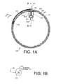
- FIG. 1A shows a cross section of a cylinder 100, also referred to as imaging cylinder, that has an outer surface 111 and that in one embodiment is made of an outer layer 103, an inner layer 107 and a middle layer or core 105.
- the cylinder includes a clamping device 109 used in an embodiment of the present invention.
- the cylinder 100 is, for example, the cylinder of an external imaging cylinder imaging device for imaging flexible plates such as flexographic plates or flexographic plate segments.
- the cylinder's clamping device 109 is shown in the plate holding ("closed") position, with the end of one plate 113 clamped onto the outer surface 111 of the cylinder 100.
- the clamping device 109 includes a clamping element 115 that has a width and that extends in the axial direction of the cylinder, i.e., in the direction perpendicular to the plane of the drawing.
- the clamping element 115 and its width are configured to receive a flexible plate in the gap formed between the clamping element and the outer surface 111 of the cylinder 100, one such plate 113 is shown in FIG. 1A located on the circumferential surface 111 of the cylinder 100.
- the clamping device 109 includes a base body 117 that has a hollow interior 119, which in one embodiment has an approximately rectangular cross-section, and in another, an elliptical or circular cross-section.
- the base body 117 extends in the axial direction, and in one embodiment is fixed to the inner wall of the inner layer 107 of the cylinder 100, and in another embodiment, is incorporated with the inner wall of the inner layer 107 of the cylinder 100.
- An inflatable air hose 121 made of an inflatable material-a rubber compound in one embodiment-is mounted in the hollow interior 119 of the base body 117.
- the air hose 121 has an inflated state and an uninflated state.
- a lifting element 123 is mechanically coupled to the clamping element 115, in one embodiment using at least one guiding shaft 125.
- At least one spring 127 is positioned between the lifting element 123 and the base body 117 and biased to exert a force onto the lifting element 123 to compress the inflatable air hose 121 when the hose 121 is not inflated. In one embodiment, there is one spring per guiding shaft.
- FIG. 1B shows a source of air pressure, e.g., a pump 135 that is coupled to the interior of the inflatable air hose 121 and configured to provide air pressure to the interior of the inflatable air hose 121 to inflate the hose 121.
- the pump 135 includes a motor 139 and is electrically activated by an electric switch 137 that can be operated, e.g., by the operator pushing a button or activating the pump 135 by a foot panel.
- a valve element 143 such as an air pressure switching device, e.g., a magnetic valve is included, and used by an operator or by a control system to automatically switch air pressure on or off while the pump is in operation.
- an external source of compressed air is used, and a switching device, such as a magnetic valve, is used for switching the air pressure on or off.
- FIG. 1C Such an embodiment is shown in simplified form in FIG. 1C where an automatic loader/unloader 145 is shown with an imaging cylinder 100 of an external imaging cylinder imager. Other components of the imager are not shown, as would be clear to those in the art.
- the method and apparatus described herein is readily adaptable to work in conjunction with an automatic loading device such as loader/unloader 145. At least one instance of the clamping device 109 is included on the imaging cylinder 100. Each instance includes a corresponding inflatable hose.
- a pump 141 is included and is on during operation.
- the pump 141 is coupled via at least one individual valve element 143 or valve device to a corresponding instance of a clamping device.
- each valve element is a magnetic valve.
- an operator switches the supply on or off to the corresponding clamping device's inflatable air hose to selectively provide an air supply to any selected clamping device or devices, in the example shown in FIG. 1C , a control system 147 is included to automatically switch the air supply according to the sequence of loading or unloading of the automatic loader/unloader.
- a control system 147 is a programmable microcontroller programmed to control the sequence of operation of the automatic loader/unloader 145 and of the at least one valve element 143, e.g. switching device, and corresponding clamping device.
- One embodiment includes a handling unit that is coupled to the control system 147 and that is operative, under control of the control system, to selectively hold and feed the metal bar 131 ( FIG. 1A ) onto the imaging cylinder 100.
- the handling unit includes a body 153 and a telescopic arm 155.
- One embodiment includes a motor 151 coupled to the control system 147 and operative to rotate the imaging cylinder. In one embodiment, under guidance of the control system, the motor 151 rotates the imaging cylinder so that the handling unit comprising the body 153 and the telescopic arm 155 is aligned with the magnetized element 129.
- a control system of an automatic loader/unloader (not shown in FIG. 1B ) is coupled to the switch controlling the pump, such that the air supply is switched on or off automatically according to the loading/unloading sequence.
- control system e.g., a programmed microcontroller
- switch the air supply on or off as required, e.g., by an automatic loading system coupled to or also controlled by the control system, such a controlling system controlling the pump switch in one version, and a pressure switching element such as a magnetic valve in another embodiment.
- the operator causes the source of air pressure, e.g. pump 135, to provide air pressure to the interior of the inflatable air hose 121 to inflate the hose 121. So inflating the inflatable air hose 121 causes the cross section of the hose 121 to expand.
- the air hose expanding imparts a force onto the lifting element 123 that causes the at least one spring 127 to compress the guide shaft and this causes the clamping bar to move such that a gap is created between the clamping element 115 and the outer surface 111 of the cylinder 100.
- Such a gap provides for inserting or removing the edge of a flexible plate between the clamping element 115 and the outer surface 111 of the cylinder 100.
- This state of the clamping device 109 is called the open state, and also the release state herein.
- FIG. 1A shows one end of the plate 113 clamped onto the surface 111 of the cylinder 100.
- the one edge of the plate 113 is clamped with the force of the one or more springs 127.
- the clamping element 115 is fragmented into a plurality of clamping segments in the axial direction to support clamping of more than one plate distributed in the axial direction.
- the clamping device 109 can clamp flexible plates with various thicknesses onto the surface 111 of the imaging cylinder 100.
- the imaging cylinder includes one or more magnetized elements 129 made of a magnetized material close to or on the surface 111 of the cylinder.
- a metal bar 131 e.g., in the shape of a metal ruler, and made of a material which is attracted to the magnetized material, e.g., steel-is placed over the plate near the end of the plate.
- the magnetic attraction between the metal bar 131 and the magnetized element 129 imparts a force on the plate towards the surface, and maintains the plate on the surface of the imaging cylinder.
- the magnetized element 129 is placed along the whole width of the imaging cylinder layers 103,105 and 107. The plate is thus fixed between the surface of the imaging cylinder 100 and the metal bar 131.
- FIG. 5 shows a perspective view of an embodiment of the imaging cylinder 100 with the metal bar 131 and a plate thereon, according to an embodiment of the present invention.
- the clamping element is fragmented in this embodiment. That the clamping bar is fragmented is shown more clearly in FIG. 6 , which shows a perspective view of a cutout of the imaging cylinder 100 including an embodiment of the present invention.
- the bar 115 includes a plurality of clamping segments in the axial direction to support clamping of more than one plate distributed in the axial direction.
- the metal bar 131 is fixed by two fixing elements 133 on each side of the imaging cylinder, as seen in FIG. 1A and FIG. 5 .
- the fixing elements 133 are bolts
- the imaging cylinder 100 has matching tapped holes made for the bolts to be afixed thereto.
- FIG. 1A shows the metal bar and fixing elements 133 in the unfixed position, while FIG. 1C shows these fixed onto the cylinder 100.
- the magnetized element 129 is on the surface of the imaging cylinder 100, it is known that surface differences on the surface 111 of an imaging cylinder might lead to patterns being exposed on the plate because of backreflection of energy arriving from energy pasing through the imaging cylinder and relacted back by the surface via the back of a plate during exposure. Therefore, as shown in FIG. 1A , one embodiment of the invention uses a multi-layer imaging cylinder, with an inner core, e.g. the middle layer 105. The magnetized element 129 is in the core between the outer and inner cylindrical surfaces 103 and 107, so hidden under the outer layer 103 of the imaging cylinder. The invetors have found that this reduces exposure problems from back-reflection due to surface differences.
- FIG. 2 shows an alternate embodiment of an imaging cylinder 200 in which the magnetized element 129 is made adjustable in the circumferential direction of a cross section perpendicular to the radial direction in a gap 205 between the outer layer 103 and inner layer 107 of the imaging cylinder 200. This allows one to fix plates of different extent. Note that the same reference numeral is used to describe the magnetized element 129, and those in the art will inderstand that a different shape element 129 might need to be used in the embodiment shown in FIG. 2 .
- FIG. 3 shows another embodiment of an imaging cylinder 300 in which a plurality of magentic elements 129 are distributed along the circumferential direction between the outer layer 103 and the inner layer 107 of the imaging cylinder 300 so that plates of different lengths can be placed on the surface 111 of the imaging cylinder 300.
- one end of the plate is clamped using the clamping device 109, and the other end is fixed onto the surface of the imaging clyinder using a metal bar 131.
- FIG. 4A shows a cross section of yet another embodiment of an imaging cylinder 400 in which the core layer 105, e.g. the middle layer 105, between the outer layer 103 and inner layer 107 of the cylinder has a plurality of magnetized elements 405 that extend the whole circumference of the the core layer, e.g. the middle layer 105.
- the core layer 105 e.g. the middle layer 105
- the outer layer 103 and inner layer 107 of the cylinder has a plurality of magnetized elements 405 that extend the whole circumference of the the core layer, e.g. the middle layer 105.
- FIG. 4B shows a view of the core layer, e.g. the middle layer 105, including the magnetized elements 405.
- FIG. 4A shows a plurality of metal bars 131 and fixing elements 133 at various circumferential locations so that plates of differnet sizes can be fixed.
- One embodiment of the invention includes the imaging cylinder 100 operating automatically.
- FIGS. 7 through 10 show different stages of operation of an automatic loader and unloader.
- Each of FIGS. 7 to 10 shows a clamping system that includes the imaging cylinder 100 as shown in FIG. 1A , and a handling unit that includes a body 153 and a telescopic extension arm 155 that is operative to selectively hold and feed the metal bar 131 onto the imaging cylinder 100.
- FIGS. 7 to 10 are other elements of an automatic loader/unloader. Such elements are shown in FIG. 1C .
- the handling unit is coupled to the control system 147 and operates under guidance of the control system.
- a motor 151 coupled to the control system 147 and operative to rotate the imaging cylinder. In one embodiment, under guidance of the control system, the motor 151 rotates the imaging cylinder so that the handling unit is aligned with the magnetized element 129.
- FIG. 7 shows one end of a plate 113 fixed onto the surface 111 of the imaging cylinder 100 by the clamping element 115 using a clamping device 109 automatically operated.
- FIG. 8 shows the system after the rotation.
- the telescopic arm 155 e.g. a telescopic extension arm, extends towards the surface 111 of the imaging cylinder 100 and feeds the steel bar 131 onto to the imaging cylinder 100's surface so that the steel bar 131 clamps the plate 113 onto the surface of the imaging cylinder 100.
- the second plate end is thus clamped onto the cylinder surface 111 by the magnetic force between the metal bar 131 and the magnetized element 129.
- the handling unit also is arranged to fix the two fixing elements onto the imaging cylinder 100 to prevent the metal bar 131 from slipping along the surface.
- FIG. 9 shows the the telescopic arm 155, e.g. a telescopic extension arm, extended towards the surface 111 of the imaging cylinder 100 and feeds the steel bar 131 onto to the imaging cylinder 100's surface.
- the telescopic arm 155 e.g. a telescopic extension arm
- FIG. 10 shows the system after the telescopic arm 155 is back in its start position.
- the plate 113 is fully mounted onto the surface 111 of the imaging cylinder, and ready for imaging.
- One embodiment is operated manually, while another embodiment is operated automatically.
- the apparatus is to clamp all types of plates of a variety of thicknesses onto the surface of an imaging cylinder.
- One embodiment avoids or reduces back-reflection exposure problems by including hidden magnet elements.
- One embodiment includes register pins.
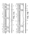
- FIG. 11A shows the section A-A shown in FIG. 1A , but with the clamping device 109 in the open position and with a plurality of clamping elements, according to a first embodiment.
- the clamping element 115 part of two adjacent clamping elements1101 and 1111 are shown.
- Each clamping element is attached to its own set of guiding shafts, three shafts 125 are shown for clamping element 115, and one guiding shaft 1102, 1112 of the respective sets of shafts attached to the clamping elements 1101 and 1111 are shown.
- the other ends of the guiding shafts are attached to respective lifting elements.
- Lifting element 123 is coupled to all shafts 125 and clamping element 115, while parts of lifting elements 1103 and 1113 are coupled via shafts 1102 and 1112, respectively, to the clamping elements 1101 and 1111, respectively.
- a first set of springs 127 is shown around shafts 125, a second set around shafts 1102, and a third set around shafts 1112.
- FIG. 11B shows the section A-A shown in FIG. 1A , according to a different second embodiment.
- each clamping element typically has more than one, e.g., two guiding shafts.
- Each guiding shaft has its own separate lifting element, rather than the lifting element shown attached to all guiding shafts of a clamping element as shown in FIG. 11A .
- Each lifting element of the same clamping element can move independently, whereas in the embodiment shown in FIG. 11A , the lifting elements of that are coupled by respective guiding shafts to the same clamping element are mechanically one, so move together.
- FIG. 11A the lifting elements of that are coupled by respective guiding shafts to the same clamping element are mechanically one, so move together.
- FIG. 11B two shafts 1125 are shown for clamping element 115, and one guiding shaft 1122, 1124 of the respective pairs of shafts attached to the clamping elements 1101 and 1111 are shown.
- Lifting elements 1123 are separately coupled to each shafts 1125 and clamping element 115, while lifting elements 1104 and 1114 are coupled via shafts 1122 and 1124, respectively, to the clamping elements 1101 1 and 1111, respectively.
- a first set of springs 127 is shown around shafts 1125, a second set around shafts 1122, and a third set around shafts 1124.
- each clamping element By arranging each clamping element to have its own guiding shafts, lifting elements, and springs, for example, as in either FIG. 11A or 11B , the different clamping elements can clamp plates of different thicknesses.
- only one inflatable hose 121 is used for the whole axial length, i.e., for all the clamping elements.
- independent hoses are used such that individual clamping elements may be individually controlled by switchably supplying air pressure to respective hoses.
- an alternate embodiment includes a plurality of instances of the clamping device, such clamping devices distributed along the axial direction of the cylinder, each clamping device adapted to clamp a plate independently of the clamping by the other clamping device(s).
- the cylinder has a circumference of approximately 129 cm and an axial length of 210 cm.
- Such a cylinder 100 can accommodate, for example, plates of 50 in by 80 in.
- 20 clamping devices are distributed in the axial direction.
- FIG. 12 shows a cylinder 1200 with two instances of the clamping device: the clamping device 109, and additional clamping device 1209 that respectively includes clamping element 1215.
- the second clamping device is shown in the open (unclamping) position. Having a plurality of clamping devices in the circumferential direction provides for a plurality of plate segments that are shorter in the circumferential direction to be loaded.
- One embodiment includes clamping elements distributed at two locations in the circumferential direction. In an alternate embodiment, three locations are used in the circumferential direction.
- another aspect of the invention is a method of loading a plate onto an imaging cylinder by using the apparatus as described herein.
- the inflatable air hose 121 is inflated with air, in alternate embodiments, another gas is used, and in yet another embodiment, a liquid is used.
- outer surface 111 in this context includes the case that the outer surface 111 is somewhat indented in the area of the clamping element.
- an element described herein of an apparatus embodiment is an example of a means for carrying out the function performed by the element for the purpose of carrying out the invention.
- any one of the terms comprising, comprised of or which comprises is an open term that means including at least the elements/features that follow, but not excluding others.
- the term comprising, when used in the claims should not be interpreted as being limitative to the means or elements or steps listed thereafter.
- the scope of the expression a device comprising A and B should not be limited to devices consisting only of elements A and B.
- Any one of the terms including or which includes or that includes as used herein is also an open term that also means including at least the elements/features that follow the term, but not excluding others. Thus, including is synonymous with and means comprising.
- a device A coupled to a device B should not be limited to devices or systems wherein an output of device A is directly connected to an input of device B. It means that there exists a path between an output of A and an input of B which may be a path including other devices or means.
Landscapes
- Engineering & Computer Science (AREA)
- Mechanical Engineering (AREA)
- Manipulator (AREA)
- Length Measuring Devices By Optical Means (AREA)
- Supply, Installation And Extraction Of Printed Sheets Or Plates (AREA)
- Photographic Developing Apparatuses (AREA)
- Magnetic Resonance Imaging Apparatus (AREA)
- Studio Devices (AREA)
- Investigating Materials By The Use Of Optical Means Adapted For Particular Applications (AREA)
Applications Claiming Priority (2)
| Application Number | Priority Date | Filing Date | Title |
|---|---|---|---|
| US89069807P | 2007-02-20 | 2007-02-20 | |
| US12/021,635 US20080196614A1 (en) | 2007-02-20 | 2008-01-29 | Clamping and releasing flexible plates to and from an imaging cylinder |
Publications (3)
| Publication Number | Publication Date |
|---|---|
| EP1961568A2 true EP1961568A2 (de) | 2008-08-27 |
| EP1961568A3 EP1961568A3 (de) | 2010-01-13 |
| EP1961568B1 EP1961568B1 (de) | 2011-04-06 |
Family
ID=39410083
Family Applications (1)
| Application Number | Title | Priority Date | Filing Date |
|---|---|---|---|
| EP08075125A Active EP1961568B1 (de) | 2007-02-20 | 2008-02-19 | Einklemmen und Lösen flexibler Platten in einen bzw. aus einem Bildgebungszylinder |
Country Status (4)
| Country | Link |
|---|---|
| US (1) | US20080196614A1 (de) |
| EP (1) | EP1961568B1 (de) |
| AT (1) | ATE504444T1 (de) |
| DE (1) | DE602008005944D1 (de) |
Cited By (1)
| Publication number | Priority date | Publication date | Assignee | Title |
|---|---|---|---|---|
| CN104044339A (zh) * | 2013-03-14 | 2014-09-17 | 艾司科影像有限公司 | 将柔印板和金属背板连接到成像滚筒上的装置和方法 |
Families Citing this family (3)
| Publication number | Priority date | Publication date | Assignee | Title |
|---|---|---|---|---|
| US11628663B2 (en) * | 2021-04-08 | 2023-04-18 | PMD Dies & Stereos Proprietary Limited | Flexographic printing imaging with lead and trail edge strips |
| CN115818367A (zh) * | 2022-11-08 | 2023-03-21 | 宁德时代新能源科技股份有限公司 | 卷筒、膜层卷绕装置及电池加工系统 |
| JP2026514470A (ja) * | 2023-04-17 | 2026-05-11 | テトラ ラバル ホールディングス アンド ファイナンス エス エイ | 包装材料のウェブを製造する方法及び装置 |
Citations (3)
| Publication number | Priority date | Publication date | Assignee | Title |
|---|---|---|---|---|
| US6561094B1 (en) | 1999-05-29 | 2003-05-13 | Koenig & Bauer Aktiengesellschaft | Device for fixing a flexible plate on a printing cylinder |
| US6598530B1 (en) | 1999-05-29 | 2003-07-29 | Koenig & Bauer Aktiengesellschaft | Method for fastening a flexible plate |
| US7165492B2 (en) | 2005-02-07 | 2007-01-23 | Esko-Graphics A/S | Method and apparatus to clamp and release flexible plates onto an imaging cylinder |
Family Cites Families (10)
| Publication number | Priority date | Publication date | Assignee | Title |
|---|---|---|---|---|
| US3581257A (en) * | 1969-10-29 | 1971-05-25 | Electronic Transmission System | Magnetic holding drum |
| US4528906A (en) * | 1983-07-29 | 1985-07-16 | Riso Kagaku Corporation | System for retaining stencil printing master on printing drum |
| IT1184342B (it) * | 1985-02-27 | 1987-10-28 | G Cerruti Spa Off Mec | Procedimento per il bloccaggio di una lastra da stampa su un cilindro da stampa,dispositivo di bloccaggio nonche' relativa lastra |
| US6457410B1 (en) * | 2000-07-07 | 2002-10-01 | Presstek, Inc. | Method and apparatus for magnetically clamping printing plates |
| US7171901B2 (en) * | 2001-10-18 | 2007-02-06 | Kodak Graphic Communications Canada Company | Flexographic printing method |
| US6729234B2 (en) * | 2002-04-05 | 2004-05-04 | Agfa Corporation | Actuation system in an imaging system |
| US6722280B2 (en) * | 2002-08-09 | 2004-04-20 | Agfa Corporation | Method and system for simultaneous loading and unloading of substrates in platestter |
| US7424853B2 (en) * | 2002-09-23 | 2008-09-16 | Kodak Graphic Communications Canada Company | Imaging system with media carrier storage position |
| US6969060B2 (en) * | 2002-12-16 | 2005-11-29 | Creo Inc. | Sheet removal and conveying system |
| US20050120898A1 (en) * | 2003-12-05 | 2005-06-09 | Presstek, Inc. | Magnetic plate retention |
-
2008
- 2008-01-29 US US12/021,635 patent/US20080196614A1/en not_active Abandoned
- 2008-02-19 DE DE602008005944T patent/DE602008005944D1/de active Active
- 2008-02-19 EP EP08075125A patent/EP1961568B1/de active Active
- 2008-02-19 AT AT08075125T patent/ATE504444T1/de not_active IP Right Cessation
Patent Citations (3)
| Publication number | Priority date | Publication date | Assignee | Title |
|---|---|---|---|---|
| US6561094B1 (en) | 1999-05-29 | 2003-05-13 | Koenig & Bauer Aktiengesellschaft | Device for fixing a flexible plate on a printing cylinder |
| US6598530B1 (en) | 1999-05-29 | 2003-07-29 | Koenig & Bauer Aktiengesellschaft | Method for fastening a flexible plate |
| US7165492B2 (en) | 2005-02-07 | 2007-01-23 | Esko-Graphics A/S | Method and apparatus to clamp and release flexible plates onto an imaging cylinder |
Cited By (3)
| Publication number | Priority date | Publication date | Assignee | Title |
|---|---|---|---|---|
| CN104044339A (zh) * | 2013-03-14 | 2014-09-17 | 艾司科影像有限公司 | 将柔印板和金属背板连接到成像滚筒上的装置和方法 |
| CN106903973A (zh) * | 2013-03-14 | 2017-06-30 | 艾司科影像有限公司 | 将柔印板和金属背板连接到成像滚筒上的装置和方法 |
| CN106903973B (zh) * | 2013-03-14 | 2020-07-28 | 艾司科影像有限公司 | 将柔印板和金属背板连接到成像滚筒上的装置和方法 |
Also Published As
| Publication number | Publication date |
|---|---|
| DE602008005944D1 (de) | 2011-05-19 |
| EP1961568A3 (de) | 2010-01-13 |
| EP1961568B1 (de) | 2011-04-06 |
| ATE504444T1 (de) | 2011-04-15 |
| US20080196614A1 (en) | 2008-08-21 |
Similar Documents
| Publication | Publication Date | Title |
|---|---|---|
| EP1688796B1 (de) | Verfahren und Vorrichtung zum Klemmen und Lösen einer flexiblen Platte eines Belichtungszylinders | |
| EP1961568B1 (de) | Einklemmen und Lösen flexibler Platten in einen bzw. aus einem Bildgebungszylinder | |
| US6260482B1 (en) | Method for loading and unloading plates to external drum devices based on movable clamps | |
| US6357354B1 (en) | Method and apparatus for fitting a printing plate to a plate cylinder | |
| EP2778785B1 (de) | Verfahren und Vorrichtung zur Befestigung von Flexo- und Metallrückplatten auf einem Bildgebungszylinder | |
| JPS61104854A (ja) | 印刷装置の原紙係止装置 | |
| US4528906A (en) | System for retaining stencil printing master on printing drum | |
| EP0600244B1 (de) | Kassettenklemmvorrichtung | |
| EP1892098A2 (de) | Klemmvorrichtung zur Klemmung flexibler Platten auf einen Abbildungszylinder | |
| US6705226B1 (en) | Media clamping apparatus and method for an external drum imaging system | |
| JP2001138486A (ja) | レジスタ切欠きを備えたゴムブランケット、およびゴムブランケットのアライメントをする方法 | |
| US6659456B2 (en) | Sheet transport drum | |
| JP2005088014A (ja) | クランプ機構及びクランプ機構を有するレーザ加工機 | |
| US6672209B1 (en) | Method for magnetically tucking a printing plate into a plate cylinder | |
| US5553545A (en) | Plate clamping and tensioning apparatus for rotary printing press | |
| CN110640370A (zh) | 一种电路板焊接固定支架 | |
| US3310445A (en) | Apparatus for building tires | |
| JP4550219B2 (ja) | 印刷機胴に胴張りを張り渡す方法と装置 | |
| US20030061854A1 (en) | Hemming machine | |
| US7997198B2 (en) | Plate drum loadable as a sleeve for an imaging device | |
| JP3272660B2 (ja) | 印刷機のシリンダにおける面材取り付け装置 | |
| AU2962589A (en) | Apparatus for rotatably supporting a hollow, substantially cylindrical winding core, and winding core for supporting a coil of flexible, substantially flat products, especially printed products | |
| EP0133849A1 (de) | Halteeinrichtung für eine Druckschablone auf einem Druckzylinder | |
| JP4601750B2 (ja) | パッキン剥離方法及び装置 | |
| JPH0126463Y2 (de) |
Legal Events
| Date | Code | Title | Description |
|---|---|---|---|
| PUAI | Public reference made under article 153(3) epc to a published international application that has entered the european phase |
Free format text: ORIGINAL CODE: 0009012 |
|
| AK | Designated contracting states |
Kind code of ref document: A2 Designated state(s): AT BE BG CH CY CZ DE DK EE ES FI FR GB GR HR HU IE IS IT LI LT LU LV MC MT NL NO PL PT RO SE SI SK TR |
|
| AX | Request for extension of the european patent |
Extension state: AL BA MK RS |
|
| PUAL | Search report despatched |
Free format text: ORIGINAL CODE: 0009013 |
|
| AK | Designated contracting states |
Kind code of ref document: A3 Designated state(s): AT BE BG CH CY CZ DE DK EE ES FI FR GB GR HR HU IE IS IT LI LT LU LV MC MT NL NO PL PT RO SE SI SK TR |
|
| AX | Request for extension of the european patent |
Extension state: AL BA MK RS |
|
| RIC1 | Information provided on ipc code assigned before grant |
Ipc: B41F 27/02 20060101ALI20091209BHEP Ipc: B41F 27/12 20060101AFI20080528BHEP |
|
| 17P | Request for examination filed |
Effective date: 20100301 |
|
| AKX | Designation fees paid |
Designated state(s): AT BE BG CH CY CZ DE DK EE ES FI FR GB GR HR HU IE IS IT LI LT LU LV MC MT NL NO PL PT RO SE SI SK TR |
|
| GRAP | Despatch of communication of intention to grant a patent |
Free format text: ORIGINAL CODE: EPIDOSNIGR1 |
|
| GRAS | Grant fee paid |
Free format text: ORIGINAL CODE: EPIDOSNIGR3 |
|
| GRAA | (expected) grant |
Free format text: ORIGINAL CODE: 0009210 |
|
| AK | Designated contracting states |
Kind code of ref document: B1 Designated state(s): AT BE BG CH CY CZ DE DK EE ES FI FR GB GR HR HU IE IS IT LI LT LU LV MC MT NL NO PL PT RO SE SI SK TR |
|
| REG | Reference to a national code |
Ref country code: GB Ref legal event code: FG4D |
|
| REG | Reference to a national code |
Ref country code: CH Ref legal event code: EP |
|
| REG | Reference to a national code |
Ref country code: IE Ref legal event code: FG4D |
|
| REF | Corresponds to: |
Ref document number: 602008005944 Country of ref document: DE Date of ref document: 20110519 Kind code of ref document: P |
|
| REG | Reference to a national code |
Ref country code: DE Ref legal event code: R096 Ref document number: 602008005944 Country of ref document: DE Effective date: 20110519 |
|
| REG | Reference to a national code |
Ref country code: NL Ref legal event code: VDEP Effective date: 20110406 |
|
| PG25 | Lapsed in a contracting state [announced via postgrant information from national office to epo] |
Ref country code: SI Free format text: LAPSE BECAUSE OF FAILURE TO SUBMIT A TRANSLATION OF THE DESCRIPTION OR TO PAY THE FEE WITHIN THE PRESCRIBED TIME-LIMIT Effective date: 20110406 |
|
| LTIE | Lt: invalidation of european patent or patent extension |
Effective date: 20110406 |
|
| PG25 | Lapsed in a contracting state [announced via postgrant information from national office to epo] |
Ref country code: SE Free format text: LAPSE BECAUSE OF FAILURE TO SUBMIT A TRANSLATION OF THE DESCRIPTION OR TO PAY THE FEE WITHIN THE PRESCRIBED TIME-LIMIT Effective date: 20110406 Ref country code: PT Free format text: LAPSE BECAUSE OF FAILURE TO SUBMIT A TRANSLATION OF THE DESCRIPTION OR TO PAY THE FEE WITHIN THE PRESCRIBED TIME-LIMIT Effective date: 20110808 Ref country code: LT Free format text: LAPSE BECAUSE OF FAILURE TO SUBMIT A TRANSLATION OF THE DESCRIPTION OR TO PAY THE FEE WITHIN THE PRESCRIBED TIME-LIMIT Effective date: 20110406 Ref country code: HR Free format text: LAPSE BECAUSE OF FAILURE TO SUBMIT A TRANSLATION OF THE DESCRIPTION OR TO PAY THE FEE WITHIN THE PRESCRIBED TIME-LIMIT Effective date: 20110406 Ref country code: NO Free format text: LAPSE BECAUSE OF FAILURE TO SUBMIT A TRANSLATION OF THE DESCRIPTION OR TO PAY THE FEE WITHIN THE PRESCRIBED TIME-LIMIT Effective date: 20110706 |
|
| PG25 | Lapsed in a contracting state [announced via postgrant information from national office to epo] |
Ref country code: CY Free format text: LAPSE BECAUSE OF FAILURE TO SUBMIT A TRANSLATION OF THE DESCRIPTION OR TO PAY THE FEE WITHIN THE PRESCRIBED TIME-LIMIT Effective date: 20110406 Ref country code: ES Free format text: LAPSE BECAUSE OF FAILURE TO SUBMIT A TRANSLATION OF THE DESCRIPTION OR TO PAY THE FEE WITHIN THE PRESCRIBED TIME-LIMIT Effective date: 20110717 Ref country code: AT Free format text: LAPSE BECAUSE OF FAILURE TO SUBMIT A TRANSLATION OF THE DESCRIPTION OR TO PAY THE FEE WITHIN THE PRESCRIBED TIME-LIMIT Effective date: 20110406 Ref country code: GR Free format text: LAPSE BECAUSE OF FAILURE TO SUBMIT A TRANSLATION OF THE DESCRIPTION OR TO PAY THE FEE WITHIN THE PRESCRIBED TIME-LIMIT Effective date: 20110707 Ref country code: FI Free format text: LAPSE BECAUSE OF FAILURE TO SUBMIT A TRANSLATION OF THE DESCRIPTION OR TO PAY THE FEE WITHIN THE PRESCRIBED TIME-LIMIT Effective date: 20110406 Ref country code: IS Free format text: LAPSE BECAUSE OF FAILURE TO SUBMIT A TRANSLATION OF THE DESCRIPTION OR TO PAY THE FEE WITHIN THE PRESCRIBED TIME-LIMIT Effective date: 20110806 Ref country code: BE Free format text: LAPSE BECAUSE OF FAILURE TO SUBMIT A TRANSLATION OF THE DESCRIPTION OR TO PAY THE FEE WITHIN THE PRESCRIBED TIME-LIMIT Effective date: 20110406 Ref country code: LV Free format text: LAPSE BECAUSE OF FAILURE TO SUBMIT A TRANSLATION OF THE DESCRIPTION OR TO PAY THE FEE WITHIN THE PRESCRIBED TIME-LIMIT Effective date: 20110406 |
|
| PG25 | Lapsed in a contracting state [announced via postgrant information from national office to epo] |
Ref country code: NL Free format text: LAPSE BECAUSE OF FAILURE TO SUBMIT A TRANSLATION OF THE DESCRIPTION OR TO PAY THE FEE WITHIN THE PRESCRIBED TIME-LIMIT Effective date: 20110406 |
|
| PG25 | Lapsed in a contracting state [announced via postgrant information from national office to epo] |
Ref country code: EE Free format text: LAPSE BECAUSE OF FAILURE TO SUBMIT A TRANSLATION OF THE DESCRIPTION OR TO PAY THE FEE WITHIN THE PRESCRIBED TIME-LIMIT Effective date: 20110406 Ref country code: CZ Free format text: LAPSE BECAUSE OF FAILURE TO SUBMIT A TRANSLATION OF THE DESCRIPTION OR TO PAY THE FEE WITHIN THE PRESCRIBED TIME-LIMIT Effective date: 20110406 |
|
| PLBE | No opposition filed within time limit |
Free format text: ORIGINAL CODE: 0009261 |
|
| STAA | Information on the status of an ep patent application or granted ep patent |
Free format text: STATUS: NO OPPOSITION FILED WITHIN TIME LIMIT |
|
| PG25 | Lapsed in a contracting state [announced via postgrant information from national office to epo] |
Ref country code: PL Free format text: LAPSE BECAUSE OF FAILURE TO SUBMIT A TRANSLATION OF THE DESCRIPTION OR TO PAY THE FEE WITHIN THE PRESCRIBED TIME-LIMIT Effective date: 20110406 Ref country code: RO Free format text: LAPSE BECAUSE OF FAILURE TO SUBMIT A TRANSLATION OF THE DESCRIPTION OR TO PAY THE FEE WITHIN THE PRESCRIBED TIME-LIMIT Effective date: 20110406 Ref country code: SK Free format text: LAPSE BECAUSE OF FAILURE TO SUBMIT A TRANSLATION OF THE DESCRIPTION OR TO PAY THE FEE WITHIN THE PRESCRIBED TIME-LIMIT Effective date: 20110406 Ref country code: DK Free format text: LAPSE BECAUSE OF FAILURE TO SUBMIT A TRANSLATION OF THE DESCRIPTION OR TO PAY THE FEE WITHIN THE PRESCRIBED TIME-LIMIT Effective date: 20110406 |
|
| 26N | No opposition filed |
Effective date: 20120110 |
|
| REG | Reference to a national code |
Ref country code: DE Ref legal event code: R097 Ref document number: 602008005944 Country of ref document: DE Effective date: 20120110 |
|
| PG25 | Lapsed in a contracting state [announced via postgrant information from national office to epo] |
Ref country code: MC Free format text: LAPSE BECAUSE OF NON-PAYMENT OF DUE FEES Effective date: 20120229 |
|
| REG | Reference to a national code |
Ref country code: CH Ref legal event code: PL |
|
| GBPC | Gb: european patent ceased through non-payment of renewal fee |
Effective date: 20120219 |
|
| PG25 | Lapsed in a contracting state [announced via postgrant information from national office to epo] |
Ref country code: CH Free format text: LAPSE BECAUSE OF NON-PAYMENT OF DUE FEES Effective date: 20120229 Ref country code: LI Free format text: LAPSE BECAUSE OF NON-PAYMENT OF DUE FEES Effective date: 20120229 |
|
| REG | Reference to a national code |
Ref country code: IE Ref legal event code: MM4A |
|
| REG | Reference to a national code |
Ref country code: FR Ref legal event code: ST Effective date: 20121031 |
|
| PG25 | Lapsed in a contracting state [announced via postgrant information from national office to epo] |
Ref country code: IE Free format text: LAPSE BECAUSE OF NON-PAYMENT OF DUE FEES Effective date: 20120219 Ref country code: FR Free format text: LAPSE BECAUSE OF NON-PAYMENT OF DUE FEES Effective date: 20120229 Ref country code: GB Free format text: LAPSE BECAUSE OF NON-PAYMENT OF DUE FEES Effective date: 20120219 |
|
| PG25 | Lapsed in a contracting state [announced via postgrant information from national office to epo] |
Ref country code: BG Free format text: LAPSE BECAUSE OF FAILURE TO SUBMIT A TRANSLATION OF THE DESCRIPTION OR TO PAY THE FEE WITHIN THE PRESCRIBED TIME-LIMIT Effective date: 20110706 |
|
| PG25 | Lapsed in a contracting state [announced via postgrant information from national office to epo] |
Ref country code: MT Free format text: LAPSE BECAUSE OF FAILURE TO SUBMIT A TRANSLATION OF THE DESCRIPTION OR TO PAY THE FEE WITHIN THE PRESCRIBED TIME-LIMIT Effective date: 20110406 |
|
| PG25 | Lapsed in a contracting state [announced via postgrant information from national office to epo] |
Ref country code: TR Free format text: LAPSE BECAUSE OF FAILURE TO SUBMIT A TRANSLATION OF THE DESCRIPTION OR TO PAY THE FEE WITHIN THE PRESCRIBED TIME-LIMIT Effective date: 20110406 |
|
| PG25 | Lapsed in a contracting state [announced via postgrant information from national office to epo] |
Ref country code: LU Free format text: LAPSE BECAUSE OF NON-PAYMENT OF DUE FEES Effective date: 20120219 |
|
| PG25 | Lapsed in a contracting state [announced via postgrant information from national office to epo] |
Ref country code: HU Free format text: LAPSE BECAUSE OF FAILURE TO SUBMIT A TRANSLATION OF THE DESCRIPTION OR TO PAY THE FEE WITHIN THE PRESCRIBED TIME-LIMIT Effective date: 20080219 Ref country code: IT Free format text: LAPSE BECAUSE OF FAILURE TO SUBMIT A TRANSLATION OF THE DESCRIPTION OR TO PAY THE FEE WITHIN THE PRESCRIBED TIME-LIMIT Effective date: 20110406 |
|
| PGFP | Annual fee paid to national office [announced via postgrant information from national office to epo] |
Ref country code: DE Payment date: 20260218 Year of fee payment: 19 |