EP1961601A2 - Dispositif de refroidissement de batterie pour véhicules et son procédé de contrôle - Google Patents
Dispositif de refroidissement de batterie pour véhicules et son procédé de contrôle Download PDFInfo
- Publication number
- EP1961601A2 EP1961601A2 EP08290169A EP08290169A EP1961601A2 EP 1961601 A2 EP1961601 A2 EP 1961601A2 EP 08290169 A EP08290169 A EP 08290169A EP 08290169 A EP08290169 A EP 08290169A EP 1961601 A2 EP1961601 A2 EP 1961601A2
- Authority
- EP
- European Patent Office
- Prior art keywords
- battery
- temperature
- cooling water
- air
- heat exchanger
- Prior art date
- Legal status (The legal status is an assumption and is not a legal conclusion. Google has not performed a legal analysis and makes no representation as to the accuracy of the status listed.)
- Granted
Links
Images



Classifications
-
- B—PERFORMING OPERATIONS; TRANSPORTING
- B60—VEHICLES IN GENERAL
- B60K—ARRANGEMENT OR MOUNTING OF PROPULSION UNITS OR OF TRANSMISSIONS IN VEHICLES; ARRANGEMENT OR MOUNTING OF PLURAL DIVERSE PRIME-MOVERS IN VEHICLES; AUXILIARY DRIVES FOR VEHICLES; INSTRUMENTATION OR DASHBOARDS FOR VEHICLES; ARRANGEMENTS IN CONNECTION WITH COOLING, AIR INTAKE, GAS EXHAUST OR FUEL SUPPLY OF PROPULSION UNITS IN VEHICLES
- B60K1/00—Arrangement or mounting of electrical propulsion units
- B60K1/04—Arrangement or mounting of electrical propulsion units of the electric storage means for propulsion
-
- B—PERFORMING OPERATIONS; TRANSPORTING
- B60—VEHICLES IN GENERAL
- B60H—ARRANGEMENTS OF HEATING, COOLING, VENTILATING OR OTHER AIR-TREATING DEVICES SPECIALLY ADAPTED FOR PASSENGER OR GOODS SPACES OF VEHICLES
- B60H1/00—Heating, cooling or ventilating devices
- B60H1/00271—HVAC devices specially adapted for particular vehicle parts or components and being connected to the vehicle HVAC unit
- B60H1/00278—HVAC devices specially adapted for particular vehicle parts or components and being connected to the vehicle HVAC unit for the battery
-
- B—PERFORMING OPERATIONS; TRANSPORTING
- B60—VEHICLES IN GENERAL
- B60L—PROPULSION OF ELECTRICALLY-PROPELLED VEHICLES; SUPPLYING ELECTRIC POWER FOR AUXILIARY EQUIPMENT OF ELECTRICALLY-PROPELLED VEHICLES; ELECTRODYNAMIC BRAKE SYSTEMS FOR VEHICLES IN GENERAL; MAGNETIC SUSPENSION OR LEVITATION FOR VEHICLES; MONITORING OPERATING VARIABLES OF ELECTRICALLY-PROPELLED VEHICLES; ELECTRIC SAFETY DEVICES FOR ELECTRICALLY-PROPELLED VEHICLES
- B60L58/00—Methods or circuit arrangements for monitoring or controlling batteries or fuel cells, specially adapted for electric vehicles
- B60L58/10—Methods or circuit arrangements for monitoring or controlling batteries or fuel cells, specially adapted for electric vehicles for monitoring or controlling batteries
- B60L58/24—Methods or circuit arrangements for monitoring or controlling batteries or fuel cells, specially adapted for electric vehicles for monitoring or controlling batteries for controlling the temperature of batteries
-
- B—PERFORMING OPERATIONS; TRANSPORTING
- B60—VEHICLES IN GENERAL
- B60L—PROPULSION OF ELECTRICALLY-PROPELLED VEHICLES; SUPPLYING ELECTRIC POWER FOR AUXILIARY EQUIPMENT OF ELECTRICALLY-PROPELLED VEHICLES; ELECTRODYNAMIC BRAKE SYSTEMS FOR VEHICLES IN GENERAL; MAGNETIC SUSPENSION OR LEVITATION FOR VEHICLES; MONITORING OPERATING VARIABLES OF ELECTRICALLY-PROPELLED VEHICLES; ELECTRIC SAFETY DEVICES FOR ELECTRICALLY-PROPELLED VEHICLES
- B60L58/00—Methods or circuit arrangements for monitoring or controlling batteries or fuel cells, specially adapted for electric vehicles
- B60L58/10—Methods or circuit arrangements for monitoring or controlling batteries or fuel cells, specially adapted for electric vehicles for monitoring or controlling batteries
- B60L58/24—Methods or circuit arrangements for monitoring or controlling batteries or fuel cells, specially adapted for electric vehicles for monitoring or controlling batteries for controlling the temperature of batteries
- B60L58/26—Methods or circuit arrangements for monitoring or controlling batteries or fuel cells, specially adapted for electric vehicles for monitoring or controlling batteries for controlling the temperature of batteries by cooling
-
- B—PERFORMING OPERATIONS; TRANSPORTING
- B60—VEHICLES IN GENERAL
- B60H—ARRANGEMENTS OF HEATING, COOLING, VENTILATING OR OTHER AIR-TREATING DEVICES SPECIALLY ADAPTED FOR PASSENGER OR GOODS SPACES OF VEHICLES
- B60H1/00—Heating, cooling or ventilating devices
- B60H1/00271—HVAC devices specially adapted for particular vehicle parts or components and being connected to the vehicle HVAC unit
- B60H2001/00307—Component temperature regulation using a liquid flow
-
- B—PERFORMING OPERATIONS; TRANSPORTING
- B60—VEHICLES IN GENERAL
- B60K—ARRANGEMENT OR MOUNTING OF PROPULSION UNITS OR OF TRANSMISSIONS IN VEHICLES; ARRANGEMENT OR MOUNTING OF PLURAL DIVERSE PRIME-MOVERS IN VEHICLES; AUXILIARY DRIVES FOR VEHICLES; INSTRUMENTATION OR DASHBOARDS FOR VEHICLES; ARRANGEMENTS IN CONNECTION WITH COOLING, AIR INTAKE, GAS EXHAUST OR FUEL SUPPLY OF PROPULSION UNITS IN VEHICLES
- B60K1/00—Arrangement or mounting of electrical propulsion units
- B60K2001/003—Arrangement or mounting of electrical propulsion units with means for cooling the electrical propulsion units
- B60K2001/005—Arrangement or mounting of electrical propulsion units with means for cooling the electrical propulsion units the electric storage means
-
- B—PERFORMING OPERATIONS; TRANSPORTING
- B60—VEHICLES IN GENERAL
- B60K—ARRANGEMENT OR MOUNTING OF PROPULSION UNITS OR OF TRANSMISSIONS IN VEHICLES; ARRANGEMENT OR MOUNTING OF PLURAL DIVERSE PRIME-MOVERS IN VEHICLES; AUXILIARY DRIVES FOR VEHICLES; INSTRUMENTATION OR DASHBOARDS FOR VEHICLES; ARRANGEMENTS IN CONNECTION WITH COOLING, AIR INTAKE, GAS EXHAUST OR FUEL SUPPLY OF PROPULSION UNITS IN VEHICLES
- B60K1/00—Arrangement or mounting of electrical propulsion units
- B60K1/04—Arrangement or mounting of electrical propulsion units of the electric storage means for propulsion
- B60K2001/0405—Arrangement or mounting of electrical propulsion units of the electric storage means for propulsion characterised by their position
- B60K2001/0416—Arrangement in the rear part of the vehicle
-
- B—PERFORMING OPERATIONS; TRANSPORTING
- B60—VEHICLES IN GENERAL
- B60L—PROPULSION OF ELECTRICALLY-PROPELLED VEHICLES; SUPPLYING ELECTRIC POWER FOR AUXILIARY EQUIPMENT OF ELECTRICALLY-PROPELLED VEHICLES; ELECTRODYNAMIC BRAKE SYSTEMS FOR VEHICLES IN GENERAL; MAGNETIC SUSPENSION OR LEVITATION FOR VEHICLES; MONITORING OPERATING VARIABLES OF ELECTRICALLY-PROPELLED VEHICLES; ELECTRIC SAFETY DEVICES FOR ELECTRICALLY-PROPELLED VEHICLES
- B60L2240/00—Control parameters of input or output; Target parameters
- B60L2240/60—Navigation input
- B60L2240/66—Ambient conditions
- B60L2240/662—Temperature
-
- B—PERFORMING OPERATIONS; TRANSPORTING
- B60—VEHICLES IN GENERAL
- B60L—PROPULSION OF ELECTRICALLY-PROPELLED VEHICLES; SUPPLYING ELECTRIC POWER FOR AUXILIARY EQUIPMENT OF ELECTRICALLY-PROPELLED VEHICLES; ELECTRODYNAMIC BRAKE SYSTEMS FOR VEHICLES IN GENERAL; MAGNETIC SUSPENSION OR LEVITATION FOR VEHICLES; MONITORING OPERATING VARIABLES OF ELECTRICALLY-PROPELLED VEHICLES; ELECTRIC SAFETY DEVICES FOR ELECTRICALLY-PROPELLED VEHICLES
- B60L2270/00—Problem solutions or means not otherwise provided for
- B60L2270/10—Emission reduction
- B60L2270/14—Emission reduction of noise
- B60L2270/142—Emission reduction of noise acoustic
-
- B—PERFORMING OPERATIONS; TRANSPORTING
- B60—VEHICLES IN GENERAL
- B60W—CONJOINT CONTROL OF VEHICLE SUB-UNITS OF DIFFERENT TYPE OR DIFFERENT FUNCTION; CONTROL SYSTEMS SPECIALLY ADAPTED FOR HYBRID VEHICLES; ROAD VEHICLE DRIVE CONTROL SYSTEMS FOR PURPOSES NOT RELATED TO THE CONTROL OF A PARTICULAR SUB-UNIT
- B60W2510/00—Input parameters relating to a particular sub-units
- B60W2510/24—Energy storage means
- B60W2510/242—Energy storage means for electrical energy
- B60W2510/244—Charge state
-
- B—PERFORMING OPERATIONS; TRANSPORTING
- B60—VEHICLES IN GENERAL
- B60W—CONJOINT CONTROL OF VEHICLE SUB-UNITS OF DIFFERENT TYPE OR DIFFERENT FUNCTION; CONTROL SYSTEMS SPECIALLY ADAPTED FOR HYBRID VEHICLES; ROAD VEHICLE DRIVE CONTROL SYSTEMS FOR PURPOSES NOT RELATED TO THE CONTROL OF A PARTICULAR SUB-UNIT
- B60W2510/00—Input parameters relating to a particular sub-units
- B60W2510/24—Energy storage means
- B60W2510/242—Energy storage means for electrical energy
- B60W2510/246—Temperature
-
- B—PERFORMING OPERATIONS; TRANSPORTING
- B60—VEHICLES IN GENERAL
- B60W—CONJOINT CONTROL OF VEHICLE SUB-UNITS OF DIFFERENT TYPE OR DIFFERENT FUNCTION; CONTROL SYSTEMS SPECIALLY ADAPTED FOR HYBRID VEHICLES; ROAD VEHICLE DRIVE CONTROL SYSTEMS FOR PURPOSES NOT RELATED TO THE CONTROL OF A PARTICULAR SUB-UNIT
- B60W2555/00—Input parameters relating to exterior conditions, not covered by groups B60W2552/00, B60W2554/00
- B60W2555/20—Ambient conditions, e.g. wind or rain
-
- Y—GENERAL TAGGING OF NEW TECHNOLOGICAL DEVELOPMENTS; GENERAL TAGGING OF CROSS-SECTIONAL TECHNOLOGIES SPANNING OVER SEVERAL SECTIONS OF THE IPC; TECHNICAL SUBJECTS COVERED BY FORMER USPC CROSS-REFERENCE ART COLLECTIONS [XRACs] AND DIGESTS
- Y02—TECHNOLOGIES OR APPLICATIONS FOR MITIGATION OR ADAPTATION AGAINST CLIMATE CHANGE
- Y02T—CLIMATE CHANGE MITIGATION TECHNOLOGIES RELATED TO TRANSPORTATION
- Y02T10/00—Road transport of goods or passengers
- Y02T10/60—Other road transportation technologies with climate change mitigation effect
- Y02T10/70—Energy storage systems for electromobility, e.g. batteries
-
- Y—GENERAL TAGGING OF NEW TECHNOLOGICAL DEVELOPMENTS; GENERAL TAGGING OF CROSS-SECTIONAL TECHNOLOGIES SPANNING OVER SEVERAL SECTIONS OF THE IPC; TECHNICAL SUBJECTS COVERED BY FORMER USPC CROSS-REFERENCE ART COLLECTIONS [XRACs] AND DIGESTS
- Y02—TECHNOLOGIES OR APPLICATIONS FOR MITIGATION OR ADAPTATION AGAINST CLIMATE CHANGE
- Y02T—CLIMATE CHANGE MITIGATION TECHNOLOGIES RELATED TO TRANSPORTATION
- Y02T10/00—Road transport of goods or passengers
- Y02T10/60—Other road transportation technologies with climate change mitigation effect
- Y02T10/72—Electric energy management in electromobility
-
- Y—GENERAL TAGGING OF NEW TECHNOLOGICAL DEVELOPMENTS; GENERAL TAGGING OF CROSS-SECTIONAL TECHNOLOGIES SPANNING OVER SEVERAL SECTIONS OF THE IPC; TECHNICAL SUBJECTS COVERED BY FORMER USPC CROSS-REFERENCE ART COLLECTIONS [XRACs] AND DIGESTS
- Y02—TECHNOLOGIES OR APPLICATIONS FOR MITIGATION OR ADAPTATION AGAINST CLIMATE CHANGE
- Y02T—CLIMATE CHANGE MITIGATION TECHNOLOGIES RELATED TO TRANSPORTATION
- Y02T90/00—Enabling technologies or technologies with a potential or indirect contribution to GHG emissions mitigation
- Y02T90/10—Technologies relating to charging of electric vehicles
- Y02T90/16—Information or communication technologies improving the operation of electric vehicles
Definitions
- the present invention relates to a battery cooling device for vehicles and control method thereof, and more particularly, to a battery cooling device for vehicles and a method for controlling the battery cooling device, which compactly includes battery heat exchanging means mounted on a battery to cool the battery in a water cooling type, and a heat exchanger, air blowing means and cooling water circulating means connected with the battery heat exchanging means, wherein operations of the air blowing means and the cooling water circulating means are controlled in such a way as to compare battery temperature, cooling water temperature and inside air temperature of the vehicle with one another, thereby enhancing efficiency of the battery by properly controlling the battery temperature, reducing power consumption and noise by properly operating the air blowing means and the cooling water circulating means, and satisfying necessary inside temperature conditions while cooling the battery using the inside air of the vehicle.
- the hybrid vehicle Since the hybrid vehicle is driven by driving forces of two kinds by linking the existing engine with a motor driven with electric energy, it can reduce environmental pollution by exhaust gas and enhance fuel efficiency. So, the hybrid vehicles are recently in the limelight in United States and Japan, and occupy its position as the next generation vehicles.
- Such a hybrid vehicle has a high capacity battery, and so, the battery supplies electric power to the motor if necessary, and is recharged with electric energy generated from a regenerative power supply when the vehicle is reduced in speed or stopped.
- the high capacity battery radiates heat while repeats electric charging and discharging and is reduced in lifespan and cannot be used in the optimum state when temperature rises rapidly, it needs a system for properly cooling the battery to keep the optimum performance.
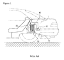
- the air-cooling type battery cooling device includes an intake duct 30 mounted in a battery case 10 mounted in a trunk room 1 of the vehicle for sucking the inside air of the vehicle, a discharge duct 40 mounted in the battery case 10 for discharging the sucked air to the outside, and a blower 50 mounted on the discharge duct 40 for promoting a good air flow.
- the inside air of the vehicle is sucked to the inside of the battery case 10 through the intake duct 30, and the sucked air is discharged to the outside through the discharge duct 40 after cooling the battery 20.
- the air-cooling type battery cooling device has several problems in that it is deteriorated in a cooling performance due to a low heat transfer efficiency of the air, and in that it is very difficult to control the inside temperature of the battery only by controlling a fan speed of the blower.
- the air-cooling type battery cooling device has a limit to enhance the cooling performance.
- the water-cooling type battery cooling device cools the battery using the cooling water of the engine cooled through a radiator, which exchanges heat with the outside air.
- the water-cooling type battery cooling device has another problem in that its cooling efficiency lowers since the cooling system introduces the outside air of high temperature thereto to cool the cooling water in the summer season.
- the present invention has been made to solve the above-mentioned problems occurring in the prior arts, and it is an object of the present invention to provide a battery cooling device for vehicles and a method for controlling the battery cooling device, which compactly includes battery heat exchanging means mounted on a battery to cooling the battery in a water cooling type, and a heat exchanger, air blowing means and cooling water circulating means connected with the battery heat exchanging means, wherein operations of the air blowing means and the cooling water circulating means are controlled in such a way as to compare battery temperature, cooling water temperature and inside air temperature of the vehicle with one another, thereby enhancing efficiency of the battery by properly controlling the battery temperature, reducing power consumption and noise by properly operating the air blowing means and the cooling water circulating means, and satisfying necessary inside temperature conditions while cooling the battery using the inside air of the vehicle.
- a battery cooling device for vehicles which cools a battery mounted in a trunk room of the vehicle, characterized in that the battery cooling device comprises: battery heat exchanging means mounted on the battery and having a passageway formed therein for allowing a circulation of cooling water; a heat exchanger connected with the battery heat exchanging means via a circulation pipe for heat-exchanging the cooling water circulating along the circulation pipe with the inside air of the vehicle; cooling water circulating means mounted on the circulation pipe for circulating the cooling water between the heat exchanger and the battery heat exchanging means; and air blowing means mounted on a side of the heat exchanger for forcedly blowing the inside air of the vehicle to the heat exchanger.
- a method for controlling a battery cooling device for vehicles which cools a battery mounted in a trunk room of the vehicle, characterized in that the control method comprises the steps of: comparing a battery temperature (Tb) and a cooling water temperature (Tw) with each other after a battery is turned on by a control signal; turning on cooling water circulating means and driving air blowing means at low speed (LOW) if the battery temperature (Tb) is higher than the cooling water temperature (Tw) as a result of the first step; turning off cooling water circulating means and driving air blowing means at low speed (LOW) if the battery temperature (Tb) is lower than the cooling water temperature (Tw) as a result of the first step; comparing a difference between the cooling water temperature (Tw) and an air temperature (Ta) with a first set temperature; continuously operating the cooling water circulating means and driving the air blowing means at high speed (HIGH) if the difference between the cooling water temperature (Tw) and the air temperature
- FIG. 1 is a view of a battery cooling device for vehicles according to a prior art
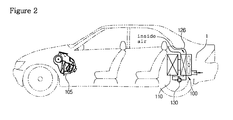
- FIG. 2 is schematic diagram showing a state where a battery cooling device for vehicles according to the present invention is installed in the vehicle;
- FIG. 3 is a structural view of the battery cooling device according to the present invention.
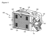
- FIG. 4 is a front perspective view of the compact-sized battery cooling device according to the present invention.
- FIG. 5 is a rear perspective view of the compact-sized battery cooling device according to the present invention.
- FIG. 6 is a perspective view of a heat exchanger of the battery cooling device according to the present invention.
- FIG. 7 is a flow chart showing a control method of the battery cooling device according to the present invention.
- FIG. 2 is schematic diagram showing a state where a battery cooling device for vehicles according to the present invention is installed in the vehicle
- FIG. 3 is a structural view of the battery cooling device according to the present invention
- FIG. 4 is a front perspective view of the compact-sized battery cooling device according to the present invention
- FIG. 5 is a rear perspective view of the compact-sized battery cooling device according to the present invention
- FIG. 6 is a perspective view of a heat exchanger of the battery cooling device according to the present invention
- FIG. 7 is a flow chart showing a control method of the battery cooling device according to the present invention.
- a battery cooling device 100 for vehicles compactly includes: battery heat exchanging means 115 mounted in a trunk room 1 of the vehicle and also mounted on a battery 110; a heat exchanger 120 connected with the battery heat exchanging means 115 through a circulation pipe 135; cooling water circulating means 130; and air blowing means 140.
- the battery 110 is mounted in the trunk room 1 of the vehicle in a state where it is inserted into a battery case 111.
- the battery heat exchanging means 115 is mounted on the battery 110, and has a passageway (not shown) formed therein for allowing a circulation of cooling water. It is preferable that the battery heat exchanging means 115 is in close contact with a side of the battery 110 in order to promote a smooth heat exchange between the cooling water circulating in the passageway and the battery 110.
- the battery heat exchanging means 115 may be mounted on the battery 110 in one of various types. That is, the battery heat exchanging means 115 may be a water jacket that surrounds the battery 110 to form a cooling water passageway between the battery heat exchanging means 115 and the battery 110, or may be a heat-exchange pipe mounted inside the battery 110.
- the heat exchanger 120 includes: a pair of tanks 123 spaced apart from each other at a predetermined interval; inlet and outlet pipes 121 and 122 formed on at least one of the tanks 123; a number of tubes 124 for communicating the tanks 123 with each other; and radiation fins 125 interposed between the tubes 124 for promoting heat exchange.
- the heat exchanger 120 further includes a housing 127 adapted to surround the heat exchanger 120, and an air temperature sensor (Ta) is mounted on a side (front side) of the housing 127, which will be described later.
- Ta air temperature sensor
- the tank 123 of the heat exchanger 120 includes a cap 128 for replenishing the tank with cooling water and a drain portion 129 for discharging the cooling water.
- a baffle (not shown) is mounted between the inlet and outlet pipes 121 and 122 inside the tank 123 to form a cooling water flow channel. That is, the cooling water introduced through the inlet pipe 121 passes through the tubes 124 arranged on a side of the baffle, and then, U-turns in the other tank 123. After that, the cooling water passes through the tubes 124 arranged on the other side of the baffle, and then, is discharged through the outlet pipe 122.
- the heat exchanger 120 and the battery 110 are connected with each other via the circulation pipe 135, namely, the inlet and outlet pipes 121 and 122 of the heat exchanger 120 are communicatably connected to the battery heat exchanging means 115 mounted on the battery 110 via the circulation pipe 135, whereby a circulation line that the cooling water can circulate the heat exchanger 120 and the battery heat exchanging means 115 of the battery 110 is constructed.
- the cooling water circulation line is a line independent of the cooling water circulation line of an engine.
- the heat exchanger 120 has a duct 126 mounted on the front part thereof for communicating the inside of the vehicle with the heat exchanger 120 so that the inside air of the vehicle can be introduced into the heat exchanger 120 when the air blowing means 140 is operated.
- the cooling water circulating means 130 is mounted on the circulation pipe 135 to forcedly circulate the cooling water between the heat exchanger 120 and the battery heat exchanging means 115.
- the cooling water circulating means 130 is a water pump mounted on the circulation pipe 135.
- the air blowing means 140 is mounted on a side of the heat exchanger 120 to forcedly blow the inside air of the vehicle to the heat exchanger 120.
- the air blowing means 140 includes: a scroll case 142 having an inlet 142a coupled to the rear portion of the heat exchanger 120 and an outlet 142b formed in a radial direction of the inlet 142a; and a fan 141 rotatably mounted inside the scroll case 142.
- the air blowing means 140 when the air blowing means 140 is operated, the inside air of the vehicle is blown to the heat exchanger 120 by a rotation of the fan 141, and the air blown to the heat exchanger 120 is sucked to the scroll case 142 after passing through the heat exchanger 120. After that, the air is discharged to the outside of the vehicle through the outlet 142b.
- the circulation pipe 135 is fixed and coupled on the rear face of the scroll case 142, and in this instance, the battery cooling device 100 can be constructed in a compact size since the circulation pipe 135 is mounted on the rear face of the scroll case 142 in such a way as to face the outlet 142b of the scroll case 142.
- the outlet 142b of the scroll case 142 is formed in the radial direction of the inlet 142a, even though the circulation pipe 135 is fixed and coupled on the rear face of the scroll case 142, there is no interference between the air discharged from the air blowing means 140 and the air discharged from the circulation pipe 135. If the air blowing means 140 is constructed of an axial fan type, it is undesirable since there is interference between the air blowing means 140 and the circulation pipe 135 while air is blown to the rear side of the heat exchanger 120.
- a battery temperature sensor (Tb) for measuring the inside temperature of the battery 110 is mounted on the battery 110, and the air temperature sensor (Ta) and a cooling water temperature sensor (Tw) are mounted on the heat exchanger 120.
- the air temperature sensor (Ta) is mounted on the front part (in a direction that the air is introduced) of the heat exchanger 120 to measure the inside air temperature of the vehicle before the air passes through the heat exchanger 120.
- the cooling water temperature sensor (Tw) is inserted and mounted to the tank 123 adjacent to the inlet pipe 121 of the heat exchanger 120 to measure temperature of the cooling water, which is introduced into the heat exchanger 120 after circulating the battery heat exchanging means 115 of the battery 110, at an inlet side of the heat exchanger 120.
- a controller 150 is connected with the battery temperature sensor (Tb), the air temperature sensor (Ta) and the cooling water temperature sensor (Tw) to control on and off states of the cooling water circulating means 130 and speed of the fan 141 of the air blowing means 140 according to a temperature value provided from each temperature sensor.
- controller 150 is also connected to the battery 110 to control the battery 110.
- FIG. 4 is a front perspective view showing an example of the battery cooling device 100 compactly including the heat exchanger 120, the air blowing means 140, the cooling water circulating means 130, and the circulation pipe 135, and
- FIG. 5 is a rear perspective view showing an example of the battery cooling device 100 compactly including the heat exchanger 120, the air blowing means 140, the cooling water circulating means 130, and the circulation pipe 135. Since the battery cooling device 110 can be installed in the vehicle in such a way as to be integrally assembled to a side of the battery case 111, a more compact-sized battery cooling device can be constructed.
- the cooling water circulating means 130 when the cooling water circulating means 130 is turned on, the cooling water circulates the heat exchanger 120, the circulation pipe 135, the battery heat exchanging means 115 of the battery 110, the circulation pipe 135, and the heat exchanger 120 in order.
- the inside air of the vehicle passes through the heat exchanger 120 by a blowing force of the air blowing means 140, and in this instance, the inside air of the vehicle heat-exchanges with the cooling water flowing inside the heat exchanger 120 to cool the cooling water, and then, is discharged to the outside of the vehicle.
- the cooling water cooled in the heat exchanger 120 cools the battery 110 while repeatedly circulating the batter heat exchanging means 115 of the battery 110.
- the unexplained reference numeral 105 designates a front air conditioner of the vehicle that selectively introduces the inside and outside air through an operation of the air blowing means and control the inside air temperature of the vehicle to temperature set by a passenger through a heat-exchange with an evaporator or a heater core.
- the cooling water circulating means 130 and the air blowing means 140 are operated at the same time to thereby cool the battery 110 through the circulation of the cooling water.
- the cooling water circulating means 130 is turned of and only the air blowing means 140 is operated to thereby cool the cooling water before the cooling water is circulated.
- the fourth step (S4) if the difference between the cooling water temperature (Tw) and the air temperature (Ta) is larger than the first set temperature (A), it means that the temperature difference is large. That is, since it means that the cooling water temperature (Tw) is higher than the inside air temperature of the vehicle, the cooling water circulating means 130 is continuously operated and the air blowing means 140 is driven at high speed (HIGH) (S5).
- the first set temperature (A) is within a range from 7°C to 12°C, which is a set temperature of the cooling water circulating means 130 to operate the cooling water circulating means 130.
- the value of the first set temperature (A) may be changed according to purposes.
- the fourth step (S4) if the difference between the cooling water temperature (Tw) and the air temperature (Ta) is lower than the first set temperature (A), it means that the temperature difference is small. That is, since it means that the cooling water temperature (Tw) is similar to the inside air temperature of the vehicle. Accordingly, the cooling water circulating means 130 is turned off to prevent a drop of cooling efficiency (S6). In the sixth step (S6), the air blowing means 140 is continuously driven at low speed (LOW).
- the air blowing means 140 is driven at high speed (HIGH) and introduces too much inside air of the vehicle into the battery cooling device, the inside air temperature of the vehicle might rise. Since the passenger may feel an unpleasant feeling due to a rise of the inside air temperature of the vehicle, if the air temperature, namely, the inside air temperature of the vehicle is higher than the second set temperature (B), in the eighth step (S8), control the air conditioner 105, which compensates the inside air temperature as much as the difference between the air temperature (Ta) and the second set temperature (B), to thereby provide an agreeable inside temperature.
- a method for compensating the inside air temperature of the vehicle convert an outside air introducing mode of the front air conditioner 105 into an inside air introducing mode, increase an air volume of air blowing means (not shown) of the front air conditioner 105, or rapidly make the inside air temperature lower than the second set temperature (B) by increasing the working ratio of a compressor (not shown) of the front air conditioner 105.
- While to increase the working ratio of the compressor means to lower a compressor cutoff temperature to thereby enhance an ON ratio of the compressor in case of a fixed capacity type compressor, it means to increase a discharged refrigerant amount by adjusting an inclination angle of a swash plate in case of a variable capacity type compressor.
- the second set temperature is within a range from 27°C to 29°C, which is a temperature necessary in an idle state of an air conditioner of the vehicle.
- the value of the second set temperature (B) may be changed according to purposes.
- the battery cooling device compactly includes the battery heat exchanging means mounted on the battery to cooling the battery in the water cooling type, and the heat exchanger, the air blowing means and the cooling water circulating means connected with the battery heat exchanging means, the operations of the air blowing means and the cooling water circulating means are controlled in such a way as to compare the battery temperature, cooling water temperature and inside air temperature of the vehicle with one another. Accordingly, the present invention can enhance efficiency of the battery by properly controlling the battery temperature, reduce power consumption and noise by properly operating the air blowing means and the cooling water circulating means, and satisfy necessary inside temperature conditions while cooling the battery using the inside air of the vehicle.
Landscapes
- Engineering & Computer Science (AREA)
- Mechanical Engineering (AREA)
- Transportation (AREA)
- Sustainable Energy (AREA)
- Power Engineering (AREA)
- Life Sciences & Earth Sciences (AREA)
- Sustainable Development (AREA)
- Physics & Mathematics (AREA)
- Thermal Sciences (AREA)
- Chemical & Material Sciences (AREA)
- Combustion & Propulsion (AREA)
- Cooling, Air Intake And Gas Exhaust, And Fuel Tank Arrangements In Propulsion Units (AREA)
- Electric Propulsion And Braking For Vehicles (AREA)
- Arrangement Or Mounting Of Propulsion Units For Vehicles (AREA)
Applications Claiming Priority (2)
| Application Number | Priority Date | Filing Date | Title |
|---|---|---|---|
| KR20070018158 | 2007-02-23 | ||
| KR1020080010549A KR101438438B1 (ko) | 2007-02-23 | 2008-02-01 | 차량용 배터리 냉각장치의 제어방법 |
Publications (3)
| Publication Number | Publication Date |
|---|---|
| EP1961601A2 true EP1961601A2 (fr) | 2008-08-27 |
| EP1961601A3 EP1961601A3 (fr) | 2010-08-18 |
| EP1961601B1 EP1961601B1 (fr) | 2011-09-21 |
Family
ID=39358074
Family Applications (1)
| Application Number | Title | Priority Date | Filing Date |
|---|---|---|---|
| EP08290169A Not-in-force EP1961601B1 (fr) | 2007-02-23 | 2008-02-22 | Dispositif de refroidissement de batterie pour véhicules et son procédé de contrôle |
Country Status (2)
| Country | Link |
|---|---|
| US (1) | US20080202741A1 (fr) |
| EP (1) | EP1961601B1 (fr) |
Cited By (5)
| Publication number | Priority date | Publication date | Assignee | Title |
|---|---|---|---|---|
| DE102013004304A1 (de) * | 2013-03-13 | 2014-09-18 | Audi Ag | Verfahren zum Kühlen einer Batterie und Batterieanordnung |
| US9530994B2 (en) | 2008-12-15 | 2016-12-27 | Hanon Systems | Heat exchanger for temperature control of vehicle batteries |
| CN108153346A (zh) * | 2017-11-27 | 2018-06-12 | 深圳国氢新能源科技有限公司 | 温度控制方法及装置 |
| CN109808442A (zh) * | 2017-11-20 | 2019-05-28 | 丰田自动车株式会社 | 车辆用温度调节系统 |
| CN116960101A (zh) * | 2023-07-26 | 2023-10-27 | 浙江佳博科技股份有限公司 | 一种键合金丝的高流量冷水机 |
Families Citing this family (27)
| Publication number | Priority date | Publication date | Assignee | Title |
|---|---|---|---|---|
| US7793746B2 (en) * | 2007-03-09 | 2010-09-14 | Gm Global Technology Operations, Inc. | Noise-comfort function for cooling systems with proportional variable speed fans |
| KR20090062380A (ko) * | 2007-12-13 | 2009-06-17 | 현대자동차주식회사 | 하이브리드 배터리시스템의 출구덕트 |
| JP5640382B2 (ja) | 2009-05-26 | 2014-12-17 | 日産自動車株式会社 | 車両のバッテリアセンブリ冷却構造、および、ウォータージャケット付きバッテリアセンブリ |
| DE102009035356B4 (de) * | 2009-07-30 | 2023-10-05 | Dr. Ing. H.C. F. Porsche Aktiengesellschaft | Zusatzverdampfer für eine Klimaanlage und Kraftfahrzeug damit |
| HUE066380T2 (hu) * | 2010-12-29 | 2024-08-28 | Byd Co Ltd | Akkumulátormodul, akkumulátor-hõmérséklet kezelõ rendszer és az ezt tartalmazó jármû |
| US8756857B2 (en) | 2011-01-14 | 2014-06-24 | Technologies Holdings Corp. | Hydronic heating system and method for pest control |
| US8720109B2 (en) | 2011-01-25 | 2014-05-13 | Technologies Holdings Corp. | Portable heating system for pest control |
| JP2012154092A (ja) * | 2011-01-26 | 2012-08-16 | Kobelco Contstruction Machinery Ltd | ハイブリッド建設機械 |
| US9016080B2 (en) | 2011-03-18 | 2015-04-28 | Denso International America, Inc. | Battery heating and cooling system |
| DE102013219726A1 (de) * | 2013-09-30 | 2015-04-02 | Siemens Aktiengesellschaft | Verwendung von Batterien für Schiffe |
| DE102014104969B4 (de) * | 2014-04-08 | 2019-11-21 | Hanon Systems | Klimatisierungssystem für ein Kraftfahrzeug |
| JP6465082B2 (ja) * | 2016-07-29 | 2019-02-06 | トヨタ自動車株式会社 | 車両構造 |
| CN106553514B (zh) * | 2016-08-30 | 2018-09-21 | 杭州衡源汽车科技有限公司 | 后置隔振式纯电动物流车电池包安装结构 |
| SE542097C2 (en) * | 2017-12-18 | 2020-02-25 | Scania Cv Ab | A method and system for climatization of a propulsion battery and a passenger compartment in a vehicle |
| CN110077193B (zh) * | 2018-01-25 | 2021-03-26 | 宝沃汽车(中国)有限公司 | 车辆的控制方法、系统及车辆 |
| US10814700B2 (en) | 2018-03-21 | 2020-10-27 | Ford Global Technologies, Llc | Vehicle cabin and high voltage battery thermal management system |
| CN109050289B (zh) * | 2018-07-26 | 2021-05-07 | 重庆工程职业技术学院 | 电池充电管理方法 |
| US10497996B1 (en) * | 2018-12-12 | 2019-12-03 | Cora Aero Llc | Battery with liquid temperature controlling system |
| JP7212526B2 (ja) * | 2019-01-15 | 2023-01-25 | 株式会社Subaru | 冷却システム |
| EP3988358B1 (fr) * | 2019-06-19 | 2025-04-16 | NISSAN MOTOR Co., Ltd. | Structure de montage de module de dispositif électronique sur un véhicule |
| CN112026589A (zh) * | 2019-11-28 | 2020-12-04 | 长城汽车股份有限公司 | 一种电池包控制方法、系统及车辆 |
| CN112026588B (zh) * | 2019-11-28 | 2022-05-06 | 长城汽车股份有限公司 | 一种电池包控制方法、系统及车辆 |
| KR102714488B1 (ko) * | 2019-12-12 | 2024-10-07 | 현대자동차주식회사 | 수냉식 배터리 배치구조가 개선된 하이브리드 차량 |
| WO2021164029A1 (fr) * | 2020-02-21 | 2021-08-26 | 华为技术有限公司 | Pile de charge et son procédé de commande |
| CN112208298B (zh) * | 2020-10-29 | 2022-04-08 | 中国第一汽车股份有限公司 | 一种车辆冷风控制系统、方法、车辆及存储介质 |
| KR20220135336A (ko) * | 2021-03-30 | 2022-10-07 | 현대자동차주식회사 | 차량의 공조 제어 방법 |
| CN116207428A (zh) * | 2023-03-29 | 2023-06-02 | 华北电力大学(保定) | 一种负泊松比材料的软包锂电池防振装置及其控制方法 |
Citations (2)
| Publication number | Priority date | Publication date | Assignee | Title |
|---|---|---|---|---|
| US5937664A (en) | 1997-03-05 | 1999-08-17 | Toyota Jidosha Kabushiki Kaisha | Battery cooling system for vehicle |
| US20020184908A1 (en) | 2001-06-09 | 2002-12-12 | Behr Gmbh & Co. | Vehicle cooling system for a temperature-raising device and method for the cooling of a temperature-raising device |
Family Cites Families (10)
| Publication number | Priority date | Publication date | Assignee | Title |
|---|---|---|---|---|
| DE4238364A1 (de) * | 1992-11-13 | 1994-05-26 | Behr Gmbh & Co | Einrichtung zum Kühlen von Antriebskomponenten und zum Heizen eines Fahrgastraumes eines Elektrofahrzeugs |
| US5709175A (en) * | 1995-12-19 | 1998-01-20 | Caterpillar Inc. | Cooling air system for an engine |
| US7147071B2 (en) * | 2004-02-04 | 2006-12-12 | Battelle Energy Alliance, Llc | Thermal management systems and methods |
| US6124644A (en) * | 1998-01-13 | 2000-09-26 | Modine Manufacturing Company | Single core dual circuit heat exchange system |
| US6302066B1 (en) * | 1999-04-30 | 2001-10-16 | Caterpillar Inc. | Apparatus and method of cooling a work machine |
| JP4190683B2 (ja) * | 1999-11-22 | 2008-12-03 | 株式会社小松製作所 | ファン装置 |
| FR2830926B1 (fr) * | 2001-10-12 | 2004-04-02 | Peugeot Citroen Automobiles Sa | Dispositif de regulation thermique pour vehicule automobile, notamment de type electrique ou hybride |
| JPWO2003064199A1 (ja) * | 2002-01-25 | 2005-05-26 | 株式会社ゼクセルヴァレオクライメートコントロール | 車両用バッテリ冷却装置 |
| EP1717083B1 (fr) * | 2002-06-10 | 2008-12-10 | Toyota Jidosha Kabushiki Kaisha | Véhicule à pile à combustible |
| JP4290461B2 (ja) * | 2003-04-03 | 2009-07-08 | 株式会社日立製作所 | 電動装置の冷却システムおよび冷却制御方法 |
-
2008
- 2008-02-22 US US12/072,019 patent/US20080202741A1/en not_active Abandoned
- 2008-02-22 EP EP08290169A patent/EP1961601B1/fr not_active Not-in-force
Patent Citations (2)
| Publication number | Priority date | Publication date | Assignee | Title |
|---|---|---|---|---|
| US5937664A (en) | 1997-03-05 | 1999-08-17 | Toyota Jidosha Kabushiki Kaisha | Battery cooling system for vehicle |
| US20020184908A1 (en) | 2001-06-09 | 2002-12-12 | Behr Gmbh & Co. | Vehicle cooling system for a temperature-raising device and method for the cooling of a temperature-raising device |
Cited By (7)
| Publication number | Priority date | Publication date | Assignee | Title |
|---|---|---|---|---|
| US9530994B2 (en) | 2008-12-15 | 2016-12-27 | Hanon Systems | Heat exchanger for temperature control of vehicle batteries |
| DE102013004304A1 (de) * | 2013-03-13 | 2014-09-18 | Audi Ag | Verfahren zum Kühlen einer Batterie und Batterieanordnung |
| DE102013004304B4 (de) | 2013-03-13 | 2022-05-12 | Audi Ag | Verfahren zum Kühlen einer Batterie und Batterieanordnung |
| CN109808442A (zh) * | 2017-11-20 | 2019-05-28 | 丰田自动车株式会社 | 车辆用温度调节系统 |
| CN109808442B (zh) * | 2017-11-20 | 2022-02-11 | 丰田自动车株式会社 | 车辆用温度调节系统 |
| CN108153346A (zh) * | 2017-11-27 | 2018-06-12 | 深圳国氢新能源科技有限公司 | 温度控制方法及装置 |
| CN116960101A (zh) * | 2023-07-26 | 2023-10-27 | 浙江佳博科技股份有限公司 | 一种键合金丝的高流量冷水机 |
Also Published As
| Publication number | Publication date |
|---|---|
| EP1961601A3 (fr) | 2010-08-18 |
| US20080202741A1 (en) | 2008-08-28 |
| EP1961601B1 (fr) | 2011-09-21 |
Similar Documents
| Publication | Publication Date | Title |
|---|---|---|
| EP1961601B1 (fr) | Dispositif de refroidissement de batterie pour véhicules et son procédé de contrôle | |
| CN115427240B (zh) | 汽车用热泵系统 | |
| CN112867615B (zh) | 热管理系统 | |
| US11541725B2 (en) | Thermal management system and integrated thermal management module for vehicle | |
| KR101776751B1 (ko) | 차량용 배터리 냉각 시스템 제어방법 | |
| KR101558611B1 (ko) | 친환경차량의 통합 열관리 시스템 | |
| CN113733848B (zh) | 一种一体化水冷混合动力汽车热管理系统 | |
| CN115303004A (zh) | 用于车辆的热泵系统 | |
| KR20200069168A (ko) | 차량용 배터리 냉각 시스템 | |
| CN113335021A (zh) | 一种增程式混合动力汽车余热回收式整车热管理系统 | |
| KR20150071540A (ko) | 차량용 에어컨 시스템 제어방법 | |
| US12337661B2 (en) | Heat pump system for vehicle | |
| CN109383229B (zh) | 一体化热管理系统 | |
| KR101438438B1 (ko) | 차량용 배터리 냉각장치의 제어방법 | |
| CN113939415A (zh) | 热管理系统 | |
| CN217835294U (zh) | 热量管理系统及车辆 | |
| US12515496B2 (en) | Integrated thermal management system | |
| CN114571949B (zh) | 一种混合动力汽车带乘员舱加热串联控制的热管理系统 | |
| US12247749B2 (en) | Air conditioning system with an integrated heat exchanger | |
| KR101927153B1 (ko) | 차량용 히트펌프 시스템 | |
| KR20120055414A (ko) | 친환경 차량용 통합 냉각 시스템 | |
| JP2924148B2 (ja) | 水冷式内燃機関の冷却装置 | |
| KR101724751B1 (ko) | 이중관이 적용된 연료전지 차량의 스택용 라디에이터 | |
| CN115091922B (zh) | 热量管理系统及控制方法 | |
| KR101596688B1 (ko) | 연료전지 차량용 쿨링 모듈 및 시스템 |
Legal Events
| Date | Code | Title | Description |
|---|---|---|---|
| PUAI | Public reference made under article 153(3) epc to a published international application that has entered the european phase |
Free format text: ORIGINAL CODE: 0009012 |
|
| AK | Designated contracting states |
Kind code of ref document: A2 Designated state(s): AT BE BG CH CY CZ DE DK EE ES FI FR GB GR HR HU IE IS IT LI LT LU LV MC MT NL NO PL PT RO SE SI SK TR |
|
| AX | Request for extension of the european patent |
Extension state: AL BA MK RS |
|
| 17P | Request for examination filed |
Effective date: 20091208 |
|
| RIC1 | Information provided on ipc code assigned before grant |
Ipc: B60H 1/00 20060101ALI20100202BHEP Ipc: B60K 1/04 20060101AFI20080527BHEP |
|
| PUAL | Search report despatched |
Free format text: ORIGINAL CODE: 0009013 |
|
| AK | Designated contracting states |
Kind code of ref document: A3 Designated state(s): AT BE BG CH CY CZ DE DK EE ES FI FR GB GR HR HU IE IS IT LI LT LU LV MC MT NL NO PL PT RO SE SI SK TR |
|
| AX | Request for extension of the european patent |
Extension state: AL BA MK RS |
|
| 17Q | First examination report despatched |
Effective date: 20100802 |
|
| GRAP | Despatch of communication of intention to grant a patent |
Free format text: ORIGINAL CODE: EPIDOSNIGR1 |
|
| RIC1 | Information provided on ipc code assigned before grant |
Ipc: B60K 1/04 20060101AFI20110217BHEP Ipc: B60H 1/00 20060101ALI20110217BHEP |
|
| AKX | Designation fees paid |
Designated state(s): AT BE BG CH CY CZ DE DK EE ES FI FR GB GR HR HU IE IS IT LI LT LU LV MC MT NL NO PL PT RO SE SI SK TR |
|
| GRAS | Grant fee paid |
Free format text: ORIGINAL CODE: EPIDOSNIGR3 |
|
| GRAA | (expected) grant |
Free format text: ORIGINAL CODE: 0009210 |
|
| AK | Designated contracting states |
Kind code of ref document: B1 Designated state(s): AT BE BG CH CY CZ DE DK EE ES FI FR GB GR HR HU IE IS IT LI LT LU LV MC MT NL NO PL PT RO SE SI SK TR |
|
| REG | Reference to a national code |
Ref country code: GB Ref legal event code: FG4D |
|
| REG | Reference to a national code |
Ref country code: CH Ref legal event code: EP |
|
| REG | Reference to a national code |
Ref country code: IE Ref legal event code: FG4D |
|
| REG | Reference to a national code |
Ref country code: DE Ref legal event code: R096 Ref document number: 602008009959 Country of ref document: DE Effective date: 20111117 |
|
| REG | Reference to a national code |
Ref country code: NL Ref legal event code: VDEP Effective date: 20110921 |
|
| PG25 | Lapsed in a contracting state [announced via postgrant information from national office to epo] |
Ref country code: HR Free format text: LAPSE BECAUSE OF FAILURE TO SUBMIT A TRANSLATION OF THE DESCRIPTION OR TO PAY THE FEE WITHIN THE PRESCRIBED TIME-LIMIT Effective date: 20110921 Ref country code: LT Free format text: LAPSE BECAUSE OF FAILURE TO SUBMIT A TRANSLATION OF THE DESCRIPTION OR TO PAY THE FEE WITHIN THE PRESCRIBED TIME-LIMIT Effective date: 20110921 Ref country code: NO Free format text: LAPSE BECAUSE OF FAILURE TO SUBMIT A TRANSLATION OF THE DESCRIPTION OR TO PAY THE FEE WITHIN THE PRESCRIBED TIME-LIMIT Effective date: 20111221 Ref country code: SE Free format text: LAPSE BECAUSE OF FAILURE TO SUBMIT A TRANSLATION OF THE DESCRIPTION OR TO PAY THE FEE WITHIN THE PRESCRIBED TIME-LIMIT Effective date: 20110921 Ref country code: FI Free format text: LAPSE BECAUSE OF FAILURE TO SUBMIT A TRANSLATION OF THE DESCRIPTION OR TO PAY THE FEE WITHIN THE PRESCRIBED TIME-LIMIT Effective date: 20110921 |
|
| LTIE | Lt: invalidation of european patent or patent extension |
Effective date: 20110921 |
|
| PG25 | Lapsed in a contracting state [announced via postgrant information from national office to epo] |
Ref country code: SI Free format text: LAPSE BECAUSE OF FAILURE TO SUBMIT A TRANSLATION OF THE DESCRIPTION OR TO PAY THE FEE WITHIN THE PRESCRIBED TIME-LIMIT Effective date: 20110921 Ref country code: GR Free format text: LAPSE BECAUSE OF FAILURE TO SUBMIT A TRANSLATION OF THE DESCRIPTION OR TO PAY THE FEE WITHIN THE PRESCRIBED TIME-LIMIT Effective date: 20111222 Ref country code: CY Free format text: LAPSE BECAUSE OF FAILURE TO SUBMIT A TRANSLATION OF THE DESCRIPTION OR TO PAY THE FEE WITHIN THE PRESCRIBED TIME-LIMIT Effective date: 20110921 Ref country code: LV Free format text: LAPSE BECAUSE OF FAILURE TO SUBMIT A TRANSLATION OF THE DESCRIPTION OR TO PAY THE FEE WITHIN THE PRESCRIBED TIME-LIMIT Effective date: 20110921 Ref country code: AT Free format text: LAPSE BECAUSE OF FAILURE TO SUBMIT A TRANSLATION OF THE DESCRIPTION OR TO PAY THE FEE WITHIN THE PRESCRIBED TIME-LIMIT Effective date: 20110921 |
|
| REG | Reference to a national code |
Ref country code: AT Ref legal event code: MK05 Ref document number: 525233 Country of ref document: AT Kind code of ref document: T Effective date: 20110921 |
|
| PG25 | Lapsed in a contracting state [announced via postgrant information from national office to epo] |
Ref country code: BE Free format text: LAPSE BECAUSE OF FAILURE TO SUBMIT A TRANSLATION OF THE DESCRIPTION OR TO PAY THE FEE WITHIN THE PRESCRIBED TIME-LIMIT Effective date: 20110921 |
|
| PG25 | Lapsed in a contracting state [announced via postgrant information from national office to epo] |
Ref country code: CZ Free format text: LAPSE BECAUSE OF FAILURE TO SUBMIT A TRANSLATION OF THE DESCRIPTION OR TO PAY THE FEE WITHIN THE PRESCRIBED TIME-LIMIT Effective date: 20110921 Ref country code: SK Free format text: LAPSE BECAUSE OF FAILURE TO SUBMIT A TRANSLATION OF THE DESCRIPTION OR TO PAY THE FEE WITHIN THE PRESCRIBED TIME-LIMIT Effective date: 20110921 Ref country code: IS Free format text: LAPSE BECAUSE OF FAILURE TO SUBMIT A TRANSLATION OF THE DESCRIPTION OR TO PAY THE FEE WITHIN THE PRESCRIBED TIME-LIMIT Effective date: 20120121 |
|
| PG25 | Lapsed in a contracting state [announced via postgrant information from national office to epo] |
Ref country code: PT Free format text: LAPSE BECAUSE OF FAILURE TO SUBMIT A TRANSLATION OF THE DESCRIPTION OR TO PAY THE FEE WITHIN THE PRESCRIBED TIME-LIMIT Effective date: 20120123 Ref country code: NL Free format text: LAPSE BECAUSE OF FAILURE TO SUBMIT A TRANSLATION OF THE DESCRIPTION OR TO PAY THE FEE WITHIN THE PRESCRIBED TIME-LIMIT Effective date: 20110921 Ref country code: IT Free format text: LAPSE BECAUSE OF FAILURE TO SUBMIT A TRANSLATION OF THE DESCRIPTION OR TO PAY THE FEE WITHIN THE PRESCRIBED TIME-LIMIT Effective date: 20110921 Ref country code: EE Free format text: LAPSE BECAUSE OF FAILURE TO SUBMIT A TRANSLATION OF THE DESCRIPTION OR TO PAY THE FEE WITHIN THE PRESCRIBED TIME-LIMIT Effective date: 20110921 Ref country code: PL Free format text: LAPSE BECAUSE OF FAILURE TO SUBMIT A TRANSLATION OF THE DESCRIPTION OR TO PAY THE FEE WITHIN THE PRESCRIBED TIME-LIMIT Effective date: 20110921 Ref country code: RO Free format text: LAPSE BECAUSE OF FAILURE TO SUBMIT A TRANSLATION OF THE DESCRIPTION OR TO PAY THE FEE WITHIN THE PRESCRIBED TIME-LIMIT Effective date: 20110921 |
|
| PLBE | No opposition filed within time limit |
Free format text: ORIGINAL CODE: 0009261 |
|
| STAA | Information on the status of an ep patent application or granted ep patent |
Free format text: STATUS: NO OPPOSITION FILED WITHIN TIME LIMIT |
|
| PG25 | Lapsed in a contracting state [announced via postgrant information from national office to epo] |
Ref country code: DK Free format text: LAPSE BECAUSE OF FAILURE TO SUBMIT A TRANSLATION OF THE DESCRIPTION OR TO PAY THE FEE WITHIN THE PRESCRIBED TIME-LIMIT Effective date: 20110921 |
|
| 26N | No opposition filed |
Effective date: 20120622 |
|
| PG25 | Lapsed in a contracting state [announced via postgrant information from national office to epo] |
Ref country code: MC Free format text: LAPSE BECAUSE OF NON-PAYMENT OF DUE FEES Effective date: 20120229 |
|
| REG | Reference to a national code |
Ref country code: CH Ref legal event code: PL |
|
| REG | Reference to a national code |
Ref country code: DE Ref legal event code: R097 Ref document number: 602008009959 Country of ref document: DE Effective date: 20120622 |
|
| GBPC | Gb: european patent ceased through non-payment of renewal fee |
Effective date: 20120222 |
|
| PG25 | Lapsed in a contracting state [announced via postgrant information from national office to epo] |
Ref country code: CH Free format text: LAPSE BECAUSE OF NON-PAYMENT OF DUE FEES Effective date: 20120229 Ref country code: LI Free format text: LAPSE BECAUSE OF NON-PAYMENT OF DUE FEES Effective date: 20120229 |
|
| REG | Reference to a national code |
Ref country code: IE Ref legal event code: MM4A |
|
| PG25 | Lapsed in a contracting state [announced via postgrant information from national office to epo] |
Ref country code: IE Free format text: LAPSE BECAUSE OF NON-PAYMENT OF DUE FEES Effective date: 20120222 Ref country code: GB Free format text: LAPSE BECAUSE OF NON-PAYMENT OF DUE FEES Effective date: 20120222 |
|
| PG25 | Lapsed in a contracting state [announced via postgrant information from national office to epo] |
Ref country code: ES Free format text: LAPSE BECAUSE OF FAILURE TO SUBMIT A TRANSLATION OF THE DESCRIPTION OR TO PAY THE FEE WITHIN THE PRESCRIBED TIME-LIMIT Effective date: 20120101 |
|
| PG25 | Lapsed in a contracting state [announced via postgrant information from national office to epo] |
Ref country code: BG Free format text: LAPSE BECAUSE OF FAILURE TO SUBMIT A TRANSLATION OF THE DESCRIPTION OR TO PAY THE FEE WITHIN THE PRESCRIBED TIME-LIMIT Effective date: 20111221 |
|
| PG25 | Lapsed in a contracting state [announced via postgrant information from national office to epo] |
Ref country code: MT Free format text: LAPSE BECAUSE OF FAILURE TO SUBMIT A TRANSLATION OF THE DESCRIPTION OR TO PAY THE FEE WITHIN THE PRESCRIBED TIME-LIMIT Effective date: 20110921 |
|
| REG | Reference to a national code |
Ref country code: DE Ref legal event code: R082 Ref document number: 602008009959 Country of ref document: DE Representative=s name: CABINET HIRSCH & ASSOCIES, FR |
|
| REG | Reference to a national code |
Ref country code: FR Ref legal event code: CD Owner name: HALLA VISTEON CLIMATE CONTROL CORPORATION Effective date: 20130827 |
|
| REG | Reference to a national code |
Ref country code: DE Ref legal event code: R081 Ref document number: 602008009959 Country of ref document: DE Owner name: HANON SYSTEMS, KR Free format text: FORMER OWNER: HALLA CLIMATE CONTROL CORP., DAEJEON, KR Effective date: 20130910 Ref country code: DE Ref legal event code: R081 Ref document number: 602008009959 Country of ref document: DE Owner name: HALLA VISTEON CLIMATE CONTROL CORP., KR Free format text: FORMER OWNER: HALLA CLIMATE CONTROL CORP., DAEJEON, KR Effective date: 20130910 Ref country code: DE Ref legal event code: R082 Ref document number: 602008009959 Country of ref document: DE Representative=s name: CABINET HIRSCH & ASSOCIES, FR Effective date: 20130910 |
|
| PG25 | Lapsed in a contracting state [announced via postgrant information from national office to epo] |
Ref country code: TR Free format text: LAPSE BECAUSE OF FAILURE TO SUBMIT A TRANSLATION OF THE DESCRIPTION OR TO PAY THE FEE WITHIN THE PRESCRIBED TIME-LIMIT Effective date: 20110921 |
|
| PG25 | Lapsed in a contracting state [announced via postgrant information from national office to epo] |
Ref country code: LU Free format text: LAPSE BECAUSE OF NON-PAYMENT OF DUE FEES Effective date: 20120222 |
|
| PG25 | Lapsed in a contracting state [announced via postgrant information from national office to epo] |
Ref country code: HU Free format text: LAPSE BECAUSE OF FAILURE TO SUBMIT A TRANSLATION OF THE DESCRIPTION OR TO PAY THE FEE WITHIN THE PRESCRIBED TIME-LIMIT Effective date: 20080222 |
|
| REG | Reference to a national code |
Ref country code: FR Ref legal event code: PLFP Year of fee payment: 9 |
|
| REG | Reference to a national code |
Ref country code: DE Ref legal event code: R082 Ref document number: 602008009959 Country of ref document: DE Representative=s name: CABINET HIRSCH & ASSOCIES, FR Ref country code: DE Ref legal event code: R081 Ref document number: 602008009959 Country of ref document: DE Owner name: HANON SYSTEMS, KR Free format text: FORMER OWNER: HALLA VISTEON CLIMATE CONTROL CORP., DAEJEON, KR |
|
| REG | Reference to a national code |
Ref country code: FR Ref legal event code: CD Owner name: HANON SYSTEMS Effective date: 20161212 |
|
| REG | Reference to a national code |
Ref country code: FR Ref legal event code: PLFP Year of fee payment: 10 |
|
| REG | Reference to a national code |
Ref country code: FR Ref legal event code: PLFP Year of fee payment: 11 |
|
| PGFP | Annual fee paid to national office [announced via postgrant information from national office to epo] |
Ref country code: DE Payment date: 20200211 Year of fee payment: 13 |
|
| PGFP | Annual fee paid to national office [announced via postgrant information from national office to epo] |
Ref country code: FR Payment date: 20210113 Year of fee payment: 14 |
|
| REG | Reference to a national code |
Ref country code: DE Ref legal event code: R119 Ref document number: 602008009959 Country of ref document: DE |
|
| PG25 | Lapsed in a contracting state [announced via postgrant information from national office to epo] |
Ref country code: DE Free format text: LAPSE BECAUSE OF NON-PAYMENT OF DUE FEES Effective date: 20210901 |
|
| PG25 | Lapsed in a contracting state [announced via postgrant information from national office to epo] |
Ref country code: FR Free format text: LAPSE BECAUSE OF NON-PAYMENT OF DUE FEES Effective date: 20220228 |