EP1961684A2 - Dispositif de rouleau de presse destine a une machine de coupe de materiau laminaire enroule - Google Patents
Dispositif de rouleau de presse destine a une machine de coupe de materiau laminaire enroule Download PDFInfo
- Publication number
- EP1961684A2 EP1961684A2 EP06841710A EP06841710A EP1961684A2 EP 1961684 A2 EP1961684 A2 EP 1961684A2 EP 06841710 A EP06841710 A EP 06841710A EP 06841710 A EP06841710 A EP 06841710A EP 1961684 A2 EP1961684 A2 EP 1961684A2
- Authority
- EP
- European Patent Office
- Prior art keywords
- pressure
- support bar
- segments
- housing
- thrust
- Prior art date
- Legal status (The legal status is an assumption and is not a legal conclusion. Google has not performed a legal analysis and makes no representation as to the accuracy of the status listed.)
- Granted
Links
Images


Classifications
-
- B—PERFORMING OPERATIONS; TRANSPORTING
- B65—CONVEYING; PACKING; STORING; HANDLING THIN OR FILAMENTARY MATERIAL
- B65H—HANDLING THIN OR FILAMENTARY MATERIAL, e.g. SHEETS, WEBS, CABLES
- B65H19/00—Changing the web roll
- B65H19/10—Changing the web roll in unwinding mechanisms or in connection with unwinding operations
- B65H19/18—Attaching, e.g. pasting, the replacement web to the expiring web
- B65H19/1842—Attaching, e.g. pasting, the replacement web to the expiring web standing splicing, i.e. the expiring web being stationary during splicing contact
- B65H19/1852—Attaching, e.g. pasting, the replacement web to the expiring web standing splicing, i.e. the expiring web being stationary during splicing contact taking place at a distance from the replacement roll
-
- B—PERFORMING OPERATIONS; TRANSPORTING
- B65—CONVEYING; PACKING; STORING; HANDLING THIN OR FILAMENTARY MATERIAL
- B65H—HANDLING THIN OR FILAMENTARY MATERIAL, e.g. SHEETS, WEBS, CABLES
- B65H18/00—Winding webs
- B65H18/08—Web-winding mechanisms
- B65H18/10—Mechanisms in which power is applied to web-roll spindle
- B65H18/106—Mechanisms in which power is applied to web-roll spindle for several juxtaposed strips
-
- B—PERFORMING OPERATIONS; TRANSPORTING
- B65—CONVEYING; PACKING; STORING; HANDLING THIN OR FILAMENTARY MATERIAL
- B65H—HANDLING THIN OR FILAMENTARY MATERIAL, e.g. SHEETS, WEBS, CABLES
- B65H18/00—Winding webs
- B65H18/08—Web-winding mechanisms
- B65H18/26—Mechanisms for controlling contact pressure on winding-web package, e.g. for regulating the quantity of air between web layers
-
- B—PERFORMING OPERATIONS; TRANSPORTING
- B65—CONVEYING; PACKING; STORING; HANDLING THIN OR FILAMENTARY MATERIAL
- B65H—HANDLING THIN OR FILAMENTARY MATERIAL, e.g. SHEETS, WEBS, CABLES
- B65H23/00—Registering, tensioning, smoothing or guiding webs
- B65H23/04—Registering, tensioning, smoothing or guiding webs longitudinally
- B65H23/044—Sensing web tension
-
- B—PERFORMING OPERATIONS; TRANSPORTING
- B65—CONVEYING; PACKING; STORING; HANDLING THIN OR FILAMENTARY MATERIAL
- B65H—HANDLING THIN OR FILAMENTARY MATERIAL, e.g. SHEETS, WEBS, CABLES
- B65H2301/00—Handling processes for sheets or webs
- B65H2301/40—Type of handling process
- B65H2301/41—Winding, unwinding
- B65H2301/414—Winding
- B65H2301/4148—Winding slitting
-
- B—PERFORMING OPERATIONS; TRANSPORTING
- B65—CONVEYING; PACKING; STORING; HANDLING THIN OR FILAMENTARY MATERIAL
- B65H—HANDLING THIN OR FILAMENTARY MATERIAL, e.g. SHEETS, WEBS, CABLES
- B65H2404/00—Parts for transporting or guiding the handled material
- B65H2404/10—Rollers
- B65H2404/13—Details of longitudinal profile
- B65H2404/133—Limited number of active elements on common axis
-
- B—PERFORMING OPERATIONS; TRANSPORTING
- B65—CONVEYING; PACKING; STORING; HANDLING THIN OR FILAMENTARY MATERIAL
- B65H—HANDLING THIN OR FILAMENTARY MATERIAL, e.g. SHEETS, WEBS, CABLES
- B65H2404/00—Parts for transporting or guiding the handled material
- B65H2404/10—Rollers
- B65H2404/13—Details of longitudinal profile
- B65H2404/137—Means for varying longitudinal profiles
-
- B—PERFORMING OPERATIONS; TRANSPORTING
- B65—CONVEYING; PACKING; STORING; HANDLING THIN OR FILAMENTARY MATERIAL
- B65H—HANDLING THIN OR FILAMENTARY MATERIAL, e.g. SHEETS, WEBS, CABLES
- B65H2404/00—Parts for transporting or guiding the handled material
- B65H2404/40—Shafts, cylinders, drums, spindles
- B65H2404/43—Rider roll construction
- B65H2404/432—Rider roll construction involving a plurality of parallel rider rolls
Definitions
- the present invention relates to a pressure roller device applied to a wound web material cutting machine, useful in the graphic arts industry to compensate for fluctuations in the thickness of the web material that is being cut and wound and to prevent the lateral sliding of web materials with a low coefficient of friction.
- Cutting-winding machines which have means for making one or more longitudinal cuts in a flexible web material unwound from a single reel, and means for re-coiling the two or more resulting strips into corresponding coaxially arranged narrower take-up reels.
- it is known to arrange a single pressure roller associated to a thruster to apply pressure on the several take-up reels as the cut material is wound.
- this single roller is not able to adapt to small differences in diameter of the take-up reels due to variations in the thickness of the cut material, so that it cannot assure that the pressure actually applied to each reel is the same.
- each assembly comprises a pivoting arm supporting the shaft of the pressure roller and a pneumatic cylinder arranged between a base plate and the pivoting arm for thrusting the roller towards the corresponding take-up reel.
- the mechanical assembly of the different pressure rollers requires leaving separation gaps between them which limit the minimum width of the take-up reels and make it difficult to adapt the system of pressure rollers to reels having different widths.
- this arrangement results in a relatively complex construction, with high manufacturing and maintenance costs.
- a pressure roller device for a wound web material cutting machine comprising in combination a support shaft on which a pressure roller is rotatably mounted, said pressure roller being formed by a plurality of adjacent pressure segments, each of said pressure segments having an outer cylindrical surface opposite an outer cylindrical surface of at least one reel; guide means adapted for guiding movements of the pressure segments in a radial direction in relation to said support shaft; and thrust means adapted for individually and independently thrusting each pressure segment guided in said guide means against said at least one reel, whereby the outer cylindrical surfaces of the pressure segments can be positioned off-centre in relation to a central line of the support bar, with different eccentricities individually determined by the contact of the outer cylindrical surface of each pressure segment with the outer cylindrical surface of the reel.
- the mentioned thrust means comprise an expandable element common for all the pressure segments, said expandable element being driven by a pressurized fluid for individually thrusting the pressure segments with a common pressure.
- the device of the present invention ensures that the same pressure will be applied in each reel, which provides a uniform hardness or compacting degree in all the reels.
- the pressure roller device of the present invention has the advantages in terms of performances of a known type construction having separate individual rollers, and however, as a result of being mounted on a common support bar, it can be supported on a support structure that is as simple as the one used for a prior art single pressure roller.
- the device of the present invention allows increasing the production time of the cutting machine, since it does not have to change the rollers to go, for example, from a single pressure roller to individual pressure rollers, nor does it have to make axial movements of the different pressure rollers in order to adjust the cutting machine to different reel widths.
- the pressure roller device of the present invention allows a smaller minimum reel width than the previously known devices.
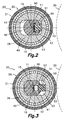
- the pressure roller device for a wound web material cutting machine comprises, according to one exemplary embodiment, a support bar 10 on which a pressure roller 20 is rotatably mounted, said pressure roller being formed by a plurality of adjacent pressure segments 25 very close to one another.
- Each of said pressure segments 25 has an outer cylindrical surface 21 opposite an outer cylindrical surface of at least one reel 30 (indicated by means of dotted lines in Figures 2 and 3 ).
- the cutting machine incorporates several take-up reels 30 for taking up and winding respective strips of material cut from a wider strip coming from a single input reel (not shown).
- the various take-up reels 30 are coaxial in relation to a shaft parallel to a central line 15 of the support bar 10, and each pressure segment 25 can correspond to one of the take-up reels 30, or there can be several pressure segments 25 for each of the several take-up reels 30.
- the cutting machine has means for moving the support bar 10 towards the take-up reels 30 to put the pressure segments 25 into contact with the same.
- the device of the present invention further comprises guide means adapted for guiding movements of the pressure segments 25 in a radial direction in relation to said support bar 10, and thrust means adapted for individually and independently thrusting each pressure segment 25 guided in said guide means against said at least one reel 30. Therefore, the outer cylindrical surfaces 21 of the pressure segments 25 can be positioned off-centre in relation to a central line 15 of the support bar 10 to compensate for differences in diameter of the several take-up reels 30 caused by possible fluctuations in the thickness of the web material that is being cut and wound.
- the pressure exerted by the pressure segments 25 on the take-up reels 30 further serves to provide a certain hardness or compacting degree to the reels and to prevent the lateral sliding of web materials with a low coefficient of friction.
- each of the pressure segments 25 is individually determined by the contact of the outer cylindrical surface 21 of each pressure segment 25 with an outer cylindrical surface of the reel 30.
- said thrust means comprise an expandable element 60 driven by a pressurized fluid common for all the pressure segments 25, the pressure segments 25 are individually thrust against the take-up reels 30 with a single pressure common to all of them.
- the support bar 10 is generally cylindrical and has formed two diametrically opposite planar outer faces 11 parallel to one another and parallel to the central line 15 of the support bar 10. These two planar outer faces 11 are in sliding contact with corresponding parallel planar inner faces 41 formed in a cavity 42 of a core 40 on which the pressure segment 25 rotates, such that said core 40 together with the pressure segment 25 can be radially moved in relation to the support bar 10.
- the planar outer faces 11 of the support bar together with the mentioned planar inner faces 41 of said core 40 form the guide means referred to above.
- the mentioned thrust means comprise, in addition to said expandable element 60, at least one thrust member 50 for each pressure segment 25.
- This thrust member 50 is located between the support bar 10 and the core 40 of the corresponding pressure segment 25, and the expandable element 60 is located along the support bar 10 between the support bar 10 and all the thrust members 50.
- the mentioned pressurized fluid is preferably pressurized air, although it could be any other gas or even a liquid.
- the expandable element 60 is substantially empty of fluid and adopts a contracted shape, so that the thrust member 50 is retracted and the pressure segment 25 can adopt an also retracted position in relation to the support bar 10.
- the expandable element 60 is full of fluid at a certain pressure, so that it is expanded up to a certain extent.
- the expansion of the expandable element 60 individually thrusts all the thrust members 50 against the respective cores 40 and the latter move radially together with the respective pressure segments 25 to an extended position in relation to the support bar 10, in which the outer cylindrical surfaces of the pressure segments 25 are in contact with the corresponding take-up reels 30.
- the expansion of the expandable element 60 allows the degree of extension of each of the different pressure segments 25 to adjust to the particular diameter of the corresponding take-up reel 30 and, however, the pressure exerted by the expandable element 60 is common and uniform for all the pressure segments 25.
- the support bar 10 has formed therealong a housing 12 in the forma of a groove with a longitudinal opening located between said two planar outer faces 11 of the support bar 10.
- Each of the thrust members 50 comprises a guide portion 51 inserted in said housing 12 of the support bar 10 such that it can slide out of and into such housing in a direction parallel to the two planar outer faces 11 of the support bar 10.
- the thrust member 50 also comprises a projecting portion 52 having an end adapted for applying pressure on an inner surface of the mentioned cavity 42 of the core 40 of the pressure segment 25 when the thrust member 50 is moved out of the housing 12.
- the expandable element 60 has the form of an expandable sleeve 60 arranged along the housing 12 from one end of the support bar 10 to the other, and placed between a bottom surface of the housing 12 and an end surface of each of said guide portions 51 of the thrust members 50.
- the expandable sleeve 60 can be connected to a pressurized fluid source through valve means associated to the support bar 10, and said valve means can be closed to retain an amount of fluid at a predetermined pressure inside the expandable sleeve 60.
- the support bar 10 has ends projecting from the pressure roller 20, and, in at least one of these projecting ends of the support bar 10 (shown in Figure 1 ), the longitudinal opening of the housing 12 has a widening 13 with a sufficient size to allow the passage of the protuberances 53 of the guide portions 51 of the thrust members 50.
- the thrust members 50 can be introduced one after another through the mentioned widening 13 and then slid along the housing 12 until their operational position.
- a stop 14 is fixed inside a portion of the housing 12 located at the projecting end of the support bar 10 and facing said widening 13. The purpose of said stop 14 is to retain the thrust members 50 inside the housing 12 of the support bar 10 once they have been introduced, preventing a movement thereof in the direction of the central line 15.
- each pressure segment 25 comprises a cover 21a of a suitable material to provide the outer cylindrical surface 21, fixed on a structural bush 29, which is rotatably mounted on its corresponding core 40 by means of a pair of bearings 26, which are of a type adapted to furthermore retain the pressure segment 25 on its corresponding core 40 against a movement in an axial direction.
- separators 27 are arranged between every two adjacent pressure segments 25 in the form of blocks of a material with a low coefficient of friction fixed to the core 40 of one of the two adjacent pressure segments 25 by means of screws 42.
- Each of these separators 27 is in sliding contact with a side surface of the core 40 of the other one of the two adjacent pressure segments 25 to allow movements of the pressure segments 25 in the radial direction along the guide means described above while at the same time they assure a minimal separation allowance between the adjacent pressure segments 25.
- stops 28 are in sliding contact with a side surface of the core 40 of the corresponding end pressure segment 25 and retain the assembly of pressure segments 25 forming the pressure roller 20 against movements in the axial direction while at the same time they allow movements of the end pressure segments 25 in the radial direction.
Landscapes
- Winding Of Webs (AREA)
- Rehabilitation Tools (AREA)
- Winding, Rewinding, Material Storage Devices (AREA)
Priority Applications (1)
| Application Number | Priority Date | Filing Date | Title |
|---|---|---|---|
| PL06841710T PL1961684T3 (pl) | 2005-12-14 | 2006-11-27 | Urządzenie z wałkiem dociskowym do maszyny używanej do cięcia warstwowego materiału nawojowego |
Applications Claiming Priority (2)
| Application Number | Priority Date | Filing Date | Title |
|---|---|---|---|
| ES200503076A ES2302416B1 (es) | 2005-12-14 | 2005-12-14 | Dispositivo de rodillo pisador para maquina cortadora de material laminar bobinado. |
| PCT/ES2006/000657 WO2007068771A2 (fr) | 2005-12-14 | 2006-11-27 | Dispositif de rouleau de presse destine a une machine de coupe de materiau laminaire enroule |
Publications (3)
| Publication Number | Publication Date |
|---|---|
| EP1961684A2 true EP1961684A2 (fr) | 2008-08-27 |
| EP1961684A4 EP1961684A4 (fr) | 2011-06-08 |
| EP1961684B1 EP1961684B1 (fr) | 2017-04-26 |
Family
ID=38163273
Family Applications (1)
| Application Number | Title | Priority Date | Filing Date |
|---|---|---|---|
| EP06841710.4A Active EP1961684B1 (fr) | 2005-12-14 | 2006-11-27 | Dispositif de rouleau de presse destiné à une machine de coupe de matériau laminaire enroulé |
Country Status (5)
| Country | Link |
|---|---|
| EP (1) | EP1961684B1 (fr) |
| CA (1) | CA2633059C (fr) |
| ES (2) | ES2302416B1 (fr) |
| PL (1) | PL1961684T3 (fr) |
| WO (1) | WO2007068771A2 (fr) |
Families Citing this family (1)
| Publication number | Priority date | Publication date | Assignee | Title |
|---|---|---|---|---|
| CN110143468B (zh) * | 2019-05-05 | 2024-05-07 | 广东盈通新材料有限公司 | 一种复卷机 |
Family Cites Families (6)
| Publication number | Priority date | Publication date | Assignee | Title |
|---|---|---|---|---|
| US4026491A (en) * | 1975-12-31 | 1977-05-31 | Theodore Bostroem | Winder drums for strip slitting lines |
| US4209138A (en) * | 1978-06-01 | 1980-06-24 | RJM Manufacturing, Inc. | Tape winding apparatus |
| US4218029A (en) * | 1979-08-16 | 1980-08-19 | Voest-Alpine Aktiengesellschaft | Upcoiler |
| US6196494B1 (en) * | 1998-10-08 | 2001-03-06 | Goldenrod Corporation | Expanding shaft |
| US6079662A (en) * | 1999-03-31 | 2000-06-27 | Tidland Corporation | Slip shaft assembly having core axial position fixing mechanism |
| US20040075011A1 (en) * | 2002-10-18 | 2004-04-22 | John Michel | Winding machine and method using interlocked rim wheels |
-
2005
- 2005-12-14 ES ES200503076A patent/ES2302416B1/es not_active Expired - Lifetime
-
2006
- 2006-11-27 ES ES06841710.4T patent/ES2632119T3/es active Active
- 2006-11-27 EP EP06841710.4A patent/EP1961684B1/fr active Active
- 2006-11-27 CA CA2633059A patent/CA2633059C/fr active Active
- 2006-11-27 PL PL06841710T patent/PL1961684T3/pl unknown
- 2006-11-27 WO PCT/ES2006/000657 patent/WO2007068771A2/fr not_active Ceased
Also Published As
| Publication number | Publication date |
|---|---|
| PL1961684T3 (pl) | 2017-10-31 |
| ES2302416A1 (es) | 2008-07-01 |
| CA2633059A1 (fr) | 2007-06-21 |
| EP1961684B1 (fr) | 2017-04-26 |
| ES2632119T3 (es) | 2017-09-11 |
| WO2007068771A3 (fr) | 2007-08-02 |
| EP1961684A4 (fr) | 2011-06-08 |
| ES2302416B1 (es) | 2009-06-10 |
| CA2633059C (fr) | 2012-04-24 |
| WO2007068771A2 (fr) | 2007-06-21 |
Similar Documents
| Publication | Publication Date | Title |
|---|---|---|
| CN110304476B (zh) | 用于切割机的摩擦轴 | |
| US4026488A (en) | Apparatus for holding cylindrical winding cores | |
| EP3770094A1 (fr) | Arbre de friction pour refendeuse | |
| CN100441329C (zh) | 可扩展和可收缩的卷芯 | |
| EP1961684B1 (fr) | Dispositif de rouleau de presse destiné à une machine de coupe de matériau laminaire enroulé | |
| US4593864A (en) | Differential mandrel for sheet-slitting machine recoiler | |
| HK1249744A1 (en) | Placement apparatus for shaft body inserts | |
| US4266737A (en) | Air differential mandrel and method of differentially winding and rewinding tapes | |
| CN101218043B (zh) | 可撑开的卷取机芯轴 | |
| US7185840B2 (en) | Web winding apparatus | |
| EP4043374B1 (fr) | Frein d'un rouleau libre d'une machine à bandes fibreuses, en particulier d'une coupeuse-bobineuse | |
| US5964430A (en) | Winding arbor | |
| EP0867391B1 (fr) | Enroulement d'une bande | |
| JP2734902B2 (ja) | テンションコントロール機能付きロール | |
| JPS60148861A (ja) | 多条帯板の定張力巻取装置 | |
| US5605302A (en) | Shaft for supporting cut roll portions in a cutting-reeling machine | |
| US5113735A (en) | Slitting apparatus | |
| EP0309018A1 (fr) | Cylindre aspirant d'alimentation et de coupe avec une fermeture coulissante pour des machines d'enroulage de bandes | |
| DE69506547T2 (de) | Achse zum Stützen von Rollenabschnitten in einer Schneide-Aufwickelmaschine | |
| JP4423673B2 (ja) | シート分割巻取装置 | |
| PL75957B1 (fr) | ||
| CN119429793B (zh) | 非接触式金属带材无损伤自动收卷方法及自动收卷机 | |
| US3497153A (en) | Core support and drive | |
| KR100845267B1 (ko) | 벨트 지지용 롤 | |
| SU933161A1 (ru) | Моталка дл намотки полос в рулон |
Legal Events
| Date | Code | Title | Description |
|---|---|---|---|
| PUAI | Public reference made under article 153(3) epc to a published international application that has entered the european phase |
Free format text: ORIGINAL CODE: 0009012 |
|
| 17P | Request for examination filed |
Effective date: 20080624 |
|
| AK | Designated contracting states |
Kind code of ref document: A2 Designated state(s): AT BE BG CH CY CZ DE DK EE ES FI FR GB GR HU IE IS IT LI LT LU LV MC NL PL PT RO SE SI SK TR |
|
| RAP1 | Party data changed (applicant data changed or rights of an application transferred) |
Owner name: COMEXI GROUP INDUSTRIES, S.A. SOCIEDAD UNIPERSONAL |
|
| A4 | Supplementary search report drawn up and despatched |
Effective date: 20110509 |
|
| DAX | Request for extension of the european patent (deleted) | ||
| REG | Reference to a national code |
Ref country code: DE Ref legal event code: R079 Ref document number: 602006052392 Country of ref document: DE Free format text: PREVIOUS MAIN CLASS: B65H0018100000 Ipc: B65H0023040000 |
|
| RIC1 | Information provided on ipc code assigned before grant |
Ipc: B65H 18/10 20060101ALI20160729BHEP Ipc: B65H 23/04 20060101AFI20160729BHEP Ipc: B65H 18/26 20060101ALI20160729BHEP |
|
| GRAP | Despatch of communication of intention to grant a patent |
Free format text: ORIGINAL CODE: EPIDOSNIGR1 |
|
| GRAS | Grant fee paid |
Free format text: ORIGINAL CODE: EPIDOSNIGR3 |
|
| INTG | Intention to grant announced |
Effective date: 20170224 |
|
| GRAA | (expected) grant |
Free format text: ORIGINAL CODE: 0009210 |
|
| AK | Designated contracting states |
Kind code of ref document: B1 Designated state(s): AT BE BG CH CY CZ DE DK EE ES FI FR GB GR HU IE IS IT LI LT LU LV MC NL PL PT RO SE SI SK TR |
|
| REG | Reference to a national code |
Ref country code: GB Ref legal event code: FG4D |
|
| REG | Reference to a national code |
Ref country code: CH Ref legal event code: EP |
|
| REG | Reference to a national code |
Ref country code: AT Ref legal event code: REF Ref document number: 887700 Country of ref document: AT Kind code of ref document: T Effective date: 20170515 |
|
| REG | Reference to a national code |
Ref country code: IE Ref legal event code: FG4D |
|
| REG | Reference to a national code |
Ref country code: DE Ref legal event code: R096 Ref document number: 602006052392 Country of ref document: DE |
|
| REG | Reference to a national code |
Ref country code: NL Ref legal event code: MP Effective date: 20170426 |
|
| REG | Reference to a national code |
Ref country code: ES Ref legal event code: FG2A Ref document number: 2632119 Country of ref document: ES Kind code of ref document: T3 Effective date: 20170911 Ref country code: LT Ref legal event code: MG4D |
|
| REG | Reference to a national code |
Ref country code: AT Ref legal event code: MK05 Ref document number: 887700 Country of ref document: AT Kind code of ref document: T Effective date: 20170426 |
|
| PG25 | Lapsed in a contracting state [announced via postgrant information from national office to epo] |
Ref country code: NL Free format text: LAPSE BECAUSE OF FAILURE TO SUBMIT A TRANSLATION OF THE DESCRIPTION OR TO PAY THE FEE WITHIN THE PRESCRIBED TIME-LIMIT Effective date: 20170426 |
|
| PG25 | Lapsed in a contracting state [announced via postgrant information from national office to epo] |
Ref country code: GR Free format text: LAPSE BECAUSE OF FAILURE TO SUBMIT A TRANSLATION OF THE DESCRIPTION OR TO PAY THE FEE WITHIN THE PRESCRIBED TIME-LIMIT Effective date: 20170727 Ref country code: LT Free format text: LAPSE BECAUSE OF FAILURE TO SUBMIT A TRANSLATION OF THE DESCRIPTION OR TO PAY THE FEE WITHIN THE PRESCRIBED TIME-LIMIT Effective date: 20170426 Ref country code: AT Free format text: LAPSE BECAUSE OF FAILURE TO SUBMIT A TRANSLATION OF THE DESCRIPTION OR TO PAY THE FEE WITHIN THE PRESCRIBED TIME-LIMIT Effective date: 20170426 Ref country code: FI Free format text: LAPSE BECAUSE OF FAILURE TO SUBMIT A TRANSLATION OF THE DESCRIPTION OR TO PAY THE FEE WITHIN THE PRESCRIBED TIME-LIMIT Effective date: 20170426 |
|
| REG | Reference to a national code |
Ref country code: FR Ref legal event code: PLFP Year of fee payment: 12 |
|
| PG25 | Lapsed in a contracting state [announced via postgrant information from national office to epo] |
Ref country code: SE Free format text: LAPSE BECAUSE OF FAILURE TO SUBMIT A TRANSLATION OF THE DESCRIPTION OR TO PAY THE FEE WITHIN THE PRESCRIBED TIME-LIMIT Effective date: 20170426 Ref country code: LV Free format text: LAPSE BECAUSE OF FAILURE TO SUBMIT A TRANSLATION OF THE DESCRIPTION OR TO PAY THE FEE WITHIN THE PRESCRIBED TIME-LIMIT Effective date: 20170426 Ref country code: BG Free format text: LAPSE BECAUSE OF FAILURE TO SUBMIT A TRANSLATION OF THE DESCRIPTION OR TO PAY THE FEE WITHIN THE PRESCRIBED TIME-LIMIT Effective date: 20170726 Ref country code: IS Free format text: LAPSE BECAUSE OF FAILURE TO SUBMIT A TRANSLATION OF THE DESCRIPTION OR TO PAY THE FEE WITHIN THE PRESCRIBED TIME-LIMIT Effective date: 20170826 |
|
| REG | Reference to a national code |
Ref country code: DE Ref legal event code: R097 Ref document number: 602006052392 Country of ref document: DE |
|
| PG25 | Lapsed in a contracting state [announced via postgrant information from national office to epo] |
Ref country code: EE Free format text: LAPSE BECAUSE OF FAILURE TO SUBMIT A TRANSLATION OF THE DESCRIPTION OR TO PAY THE FEE WITHIN THE PRESCRIBED TIME-LIMIT Effective date: 20170426 Ref country code: RO Free format text: LAPSE BECAUSE OF FAILURE TO SUBMIT A TRANSLATION OF THE DESCRIPTION OR TO PAY THE FEE WITHIN THE PRESCRIBED TIME-LIMIT Effective date: 20170426 Ref country code: DK Free format text: LAPSE BECAUSE OF FAILURE TO SUBMIT A TRANSLATION OF THE DESCRIPTION OR TO PAY THE FEE WITHIN THE PRESCRIBED TIME-LIMIT Effective date: 20170426 Ref country code: SK Free format text: LAPSE BECAUSE OF FAILURE TO SUBMIT A TRANSLATION OF THE DESCRIPTION OR TO PAY THE FEE WITHIN THE PRESCRIBED TIME-LIMIT Effective date: 20170426 |
|
| PLBE | No opposition filed within time limit |
Free format text: ORIGINAL CODE: 0009261 |
|
| STAA | Information on the status of an ep patent application or granted ep patent |
Free format text: STATUS: NO OPPOSITION FILED WITHIN TIME LIMIT |
|
| 26N | No opposition filed |
Effective date: 20180129 |
|
| PG25 | Lapsed in a contracting state [announced via postgrant information from national office to epo] |
Ref country code: SI Free format text: LAPSE BECAUSE OF FAILURE TO SUBMIT A TRANSLATION OF THE DESCRIPTION OR TO PAY THE FEE WITHIN THE PRESCRIBED TIME-LIMIT Effective date: 20170426 |
|
| PG25 | Lapsed in a contracting state [announced via postgrant information from national office to epo] |
Ref country code: MC Free format text: LAPSE BECAUSE OF FAILURE TO SUBMIT A TRANSLATION OF THE DESCRIPTION OR TO PAY THE FEE WITHIN THE PRESCRIBED TIME-LIMIT Effective date: 20170426 |
|
| PG25 | Lapsed in a contracting state [announced via postgrant information from national office to epo] |
Ref country code: CH Free format text: LAPSE BECAUSE OF NON-PAYMENT OF DUE FEES Effective date: 20171130 Ref country code: LI Free format text: LAPSE BECAUSE OF NON-PAYMENT OF DUE FEES Effective date: 20171130 |
|
| PG25 | Lapsed in a contracting state [announced via postgrant information from national office to epo] |
Ref country code: LU Free format text: LAPSE BECAUSE OF NON-PAYMENT OF DUE FEES Effective date: 20171127 |
|
| REG | Reference to a national code |
Ref country code: BE Ref legal event code: MM Effective date: 20171130 |
|
| REG | Reference to a national code |
Ref country code: IE Ref legal event code: MM4A |
|
| PG25 | Lapsed in a contracting state [announced via postgrant information from national office to epo] |
Ref country code: IE Free format text: LAPSE BECAUSE OF NON-PAYMENT OF DUE FEES Effective date: 20171127 |
|
| PG25 | Lapsed in a contracting state [announced via postgrant information from national office to epo] |
Ref country code: BE Free format text: LAPSE BECAUSE OF NON-PAYMENT OF DUE FEES Effective date: 20171130 |
|
| PG25 | Lapsed in a contracting state [announced via postgrant information from national office to epo] |
Ref country code: HU Free format text: LAPSE BECAUSE OF FAILURE TO SUBMIT A TRANSLATION OF THE DESCRIPTION OR TO PAY THE FEE WITHIN THE PRESCRIBED TIME-LIMIT; INVALID AB INITIO Effective date: 20061127 |
|
| PG25 | Lapsed in a contracting state [announced via postgrant information from national office to epo] |
Ref country code: CY Free format text: LAPSE BECAUSE OF NON-PAYMENT OF DUE FEES Effective date: 20170426 |
|
| PGFP | Annual fee paid to national office [announced via postgrant information from national office to epo] |
Ref country code: CZ Payment date: 20191121 Year of fee payment: 14 |
|
| PGFP | Annual fee paid to national office [announced via postgrant information from national office to epo] |
Ref country code: PL Payment date: 20191126 Year of fee payment: 14 Ref country code: FR Payment date: 20191125 Year of fee payment: 14 |
|
| PG25 | Lapsed in a contracting state [announced via postgrant information from national office to epo] |
Ref country code: TR Free format text: LAPSE BECAUSE OF FAILURE TO SUBMIT A TRANSLATION OF THE DESCRIPTION OR TO PAY THE FEE WITHIN THE PRESCRIBED TIME-LIMIT Effective date: 20170426 |
|
| PG25 | Lapsed in a contracting state [announced via postgrant information from national office to epo] |
Ref country code: PT Free format text: LAPSE BECAUSE OF FAILURE TO SUBMIT A TRANSLATION OF THE DESCRIPTION OR TO PAY THE FEE WITHIN THE PRESCRIBED TIME-LIMIT Effective date: 20170426 |
|
| PG25 | Lapsed in a contracting state [announced via postgrant information from national office to epo] |
Ref country code: CZ Free format text: LAPSE BECAUSE OF NON-PAYMENT OF DUE FEES Effective date: 20201127 |
|
| PG25 | Lapsed in a contracting state [announced via postgrant information from national office to epo] |
Ref country code: FR Free format text: LAPSE BECAUSE OF NON-PAYMENT OF DUE FEES Effective date: 20201130 |
|
| PG25 | Lapsed in a contracting state [announced via postgrant information from national office to epo] |
Ref country code: PL Free format text: LAPSE BECAUSE OF NON-PAYMENT OF DUE FEES Effective date: 20201127 |
|
| P01 | Opt-out of the competence of the unified patent court (upc) registered |
Effective date: 20230419 |
|
| PGFP | Annual fee paid to national office [announced via postgrant information from national office to epo] |
Ref country code: GB Payment date: 20251126 Year of fee payment: 20 |
|
| PGFP | Annual fee paid to national office [announced via postgrant information from national office to epo] |
Ref country code: IT Payment date: 20251126 Year of fee payment: 20 |
|
| PGFP | Annual fee paid to national office [announced via postgrant information from national office to epo] |
Ref country code: ES Payment date: 20251230 Year of fee payment: 20 |
|
| PGFP | Annual fee paid to national office [announced via postgrant information from national office to epo] |
Ref country code: DE Payment date: 20251224 Year of fee payment: 20 |