EP1961691A2 - Appareil de transbordement - Google Patents
Appareil de transbordement Download PDFInfo
- Publication number
- EP1961691A2 EP1961691A2 EP07023079A EP07023079A EP1961691A2 EP 1961691 A2 EP1961691 A2 EP 1961691A2 EP 07023079 A EP07023079 A EP 07023079A EP 07023079 A EP07023079 A EP 07023079A EP 1961691 A2 EP1961691 A2 EP 1961691A2
- Authority
- EP
- European Patent Office
- Prior art keywords
- arm
- cabin
- boom
- transhipment
- connecting element
- Prior art date
- Legal status (The legal status is an assumption and is not a legal conclusion. Google has not performed a legal analysis and makes no representation as to the accuracy of the status listed.)
- Granted
Links
Images



Classifications
-
- B—PERFORMING OPERATIONS; TRANSPORTING
- B66—HOISTING; LIFTING; HAULING
- B66C—CRANES; LOAD-ENGAGING ELEMENTS OR DEVICES FOR CRANES, CAPSTANS, WINCHES, OR TACKLES
- B66C13/00—Other constructional features or details
- B66C13/52—Details of compartments for driving engines or motors or of operator's stands or cabins
- B66C13/54—Operator's stands or cabins
-
- E—FIXED CONSTRUCTIONS
- E02—HYDRAULIC ENGINEERING; FOUNDATIONS; SOIL SHIFTING
- E02F—DREDGING; SOIL-SHIFTING
- E02F9/00—Component parts of dredgers or soil-shifting machines, not restricted to one of the kinds covered by groups E02F3/00 - E02F7/00
- E02F9/08—Superstructures; Supports for superstructures
- E02F9/0833—Improving access, e.g. for maintenance, steps for improving driver's access, handrails
-
- E—FIXED CONSTRUCTIONS
- E02—HYDRAULIC ENGINEERING; FOUNDATIONS; SOIL SHIFTING
- E02F—DREDGING; SOIL-SHIFTING
- E02F9/00—Component parts of dredgers or soil-shifting machines, not restricted to one of the kinds covered by groups E02F3/00 - E02F7/00
- E02F9/16—Cabins, platforms, or the like, for drivers
- E02F9/166—Cabins, platforms, or the like, for drivers movable, tiltable or pivoting, e.g. movable seats, dampening arrangements of cabins
Definitions
- the present invention relates to a transhipment apparatus having an envelope boom and a cabin boom, wherein the cabin boom comprises a first and a second arm, which are articulated to each other via a connecting element, and a first actuator for moving the first arm.
- handling equipment for example for wood, scrap or any other goods, but also to understand excavators and cranes.
- the envelope boom can be used to transfer the corresponding goods, while the cabin jib serves to adjust the position of the driver's cab. This gives the driver an improved view of the work area, such as hatches, railway carriages or the like.
- the cabin boom has for this purpose the articulated arms, via which the position of the car relative to the handling device is adjustable. The improved visibility allows more precise and faster work cycles.
- the handling equipment usually has an envelope boom and a separate cabin boom, which can be moved independently of each other.
- the envelope boom is usually arranged on the superstructure, which is rotatable relative to the undercarriage.
- the cabin boom is usually also hinged to the uppercarriage of the handling unit and laterally offset from the envelope boom. At its free end, the cabin boom carries the driver's cab, which is movable relative to the superstructure.
- Object of the present invention is therefore to provide a handling device according to the preamble of claim 1, which has an improved distribution of forces and Verstellgeometrie.
- the actuator for moving the first arm is articulated via a pivot point on the connecting element, which is arranged below the pivot points of the first arm or.
- the present invention further comprises a handling device, in which, according to the invention, the first and the second arm are each articulated on the connecting element via separate pivot axes.
- a handling device in which, according to the invention, the first and the second arm are each articulated on the connecting element via separate pivot axes.
- the handling devices according to the invention in order to achieve different reach heights or ranges, only the arms must be extended or shortened, while the kinematics with the actuators can basically remain the same. Here at most the piston diameter of the hydraulic cylinders used as actuators must be adapted. Thus, the handling device according to the invention can be adapted with minimal design effort for different operating conditions with respect to the range or reach.
- the actuator of the second arm is arranged on the underside of the second arm.
- this actuator is charged by the weight of the cabin only to pressure, so that here also results in a larger effective area. Also, the cramped space within the parallel links are avoided.
- the actuators of the first and / or the second arm are loaded by the weight of the cabin to pressure. This has the advantages already mentioned above regarding the force dissipation and the adjustment geometry.
- the driver's cab in the handling device according to the invention by force fit forcibly guided parallel or at a certain angle to the ground.
- the orientation of the cabin during movement of the cabin boom must not be readjusted, but is done automatically by positive engagement. The driver can thus bring the cabin in the desired position without changing the angle of the car to the ground.
- the first and / or the second arm designed as a parallel link. This allows in a relatively simple manner a forced parallel guidance of the driver's cab.
- the first and / or the second arm of the cabin boom according to the invention comprises at least one support element which has a closed box profile. This results in a sturdy construction which is lightweight at the same time yet stiffly responsive to bending and torsional loading.
- the first and / or the second arm is designed as a parallel link and comprises a bottom arranged main bearing element, which has a closed box profile. So takes over this main bearing element the main load, and the coupling rods and the connecting element can be made simpler and lighter in weight.
- the first and / or the second arm of the cabin boom designed as a parallel link, wherein the arm associated with this actuator from outside of the parallelogram engages the lower arm.
- the first and / or the second arm has in its interior at least one hollow profile for receiving the cables or hoses running to the driver's cab.
- these can advantageously run within the closed box profile.
- the connecting element according to the invention has a joint whose pivot axis is perpendicular to the pivot axes of the first and / or the second arm.
- the cabin can not only be adjusted with respect to the height and the boom width, but can also be pivoted laterally.
- z. B. the lateral distance between the cabin jib and the cargo handling boom are increased, which may be necessary just for bulky Umschlaggut to still get an optimal view of the loading point.
- the pivot axis of the joint runs in the vertical direction.
- the joint of the connecting element is associated with an actuator.
- the cabin can then be pivoted accordingly.
- the hinge of the connecting element connects a first and a second part of the connecting element articulated to each other, wherein the first and the second arm are articulated respectively on the first and on the second part of the connecting element.
- the first and the second arm are each articulated via separate pivot axes on the connecting element and also the actuator is not arranged between the two arms.
- the connecting element has at least five separate pivot axes, in each case two for the arms of the cabin boom designed as parallel links and one for the actuator of the first arm.
- the three bearing points for storage and adjustment of the first arm can be arranged arbitrarily to the two bearing points of the second arm, so that the movement and Verstellgeometrie the boom can be arbitrarily adapted to the application.
- the cabin jib has a docking position on the handling device, in particular on the uppercarriage of the handling device. So the driver z. B. for maintenance work on the transhipment device or the superstructure by driving the cab in the docking position.
- the cabin can be lowered by the cabin boom to the ground level.
- the driver can either get on the ground from the ground, or he can use the cabin boom to transport spare parts on the handling device or on the superstructure.
- the handling device advantageously has a platform for the transport of material, which is arranged on the cabin. This platform allows even larger elements to be transported with the cabin jib to the handling unit.
- Access to the cab takes place either from the ground when the cab is lowered to ground level or in the docking position on the superstructure. It is also conceivable that the cabin boom still has a further access position, which allows easy access to the driver's cab.
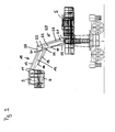
- FIG. 1 shows an embodiment of the cargo handling apparatus according to the invention with an envelope boom 1 and a cabin boom 2, which are arranged on the uppercarriage 5 of the handling device according to the invention.
- the handling device is a wheeled excavator, which can be moved over the undercarriage 6.
- the present invention can also be used for crawler excavators and other material handlers.
- the envelope boom 1 in this case has two articulated arms, which can be moved via corresponding actuators. Depending on the application, a corresponding gripper is then attached to the top of the turn-up jib with which the material to be handled can be gripped.
- Envelope 1 and cabin jib 2 are next to each other so arranged on the superstructure 5, that the movement planes of the two arms substantially are arranged parallel to each other.
- the superstructure 5 is rotatably arranged in the envelope device shown on the undercarriage 6, so that both the envelope jib and the cabin jib, which are both hinged to the superstructure 5, are rotated by rotation of the upper carriage 5 in the same way.
- the cabin boom 2 comprises a first arm 10 and a second arm 20, which are connected via a connecting element 30 hinged together.
- the first arm 10 carries the driver's cab 3 of the handling device.
- a support bracket 4 is arranged on the first arm 10, which is designed in an L-shape and on which the driver's cab 3 is mounted.
- the second arm 20, however, is hinged on the handling device, here on the superstructure 5.
- the first arm 10 is moved via an actuator 15, the second arm 20 via an actuator 25. Both actuators are designed as a hydraulic cylinder.
- the first actuator 15 is articulated to move the first arm 10 via a pivot point 33 on the connecting element 30, which is arranged below the articulation points 31 of the first arm 10.
- the first actuator 15 is only loaded on pressure.
- first arm and the second arm 20 are articulated via respective separate pivot axes 31 and 32 on the connecting element.
- first arm 10 and the second arm 20 have no common pivot axes, in turn, the adjustment and movement geometry of the cabin boom 2 can be optimally adjusted.
- the actuator 25 of the second arm 20 is disposed below the second arm 20, so that this is also loaded only by pressure.
- the first and the second arm of the cabin boom 2 are both designed as a parallel link, so that the driver's cab is positively guided by means of positive engagement parallel to the ground.
- the first arm 10 consists of a main support element 12 and a coupling rod 10 which are each articulated via articulation points 11 on the support bracket 4 and via articulation points 31 on the connecting element 30.
- the second arm 20 consists of a main support member 22 and a coupling rod 23 which are articulated via articulation points 21 on the superstructure 5 and articulation points 32 on the connecting element 30. The alignment of the articulation points 21 of the second arm 20 on the superstructure 5 to each other results automatically from the desired boom width and height of the cabin boom.
- the articulation points 21 are therefore arranged as possible in a horizontal line, whereas if a large boom width is required, the articulation points 21 are arranged more strongly in a vertical line.
- the oblique arrangement shown here is therefore a compromise of boom height and boom width.
- the range of movement of the boom according to the invention can also be adjusted accordingly by the orientation of the articulation points 31 of the first arm 10 on the connecting element.
- the use of separate articulation axes 31 and 32 of the first and second arms on the connecting element 30 results in increased flexibility with which the desired radii of movement can be easily achieved.
- the main support members 12 and 22 are embodied according to the invention as closed box sections, which gives them increased stability with a lightweight construction. Likewise, cables and hoses to the cab can be passed through the hollow sections in the main support members 12 and 22.
- the first arm 15 associated with the first arm 15 is articulated via an articulation point 33 on the connecting element 30, which is located below the articulation points 31 of the main support member 12 and coupling rod 13.
- the first actuator 15 is disposed below the first arm 10 and loaded only on pressure.
- the first actuator 15 is furthermore articulated via an articulation point 14 on the first arm 10, specifically on the main support element 12 of the parallel link arranged at the bottom.
- the second actuator 25 associated with the second arm 20 is articulated via an articulation point 24 on the main support element 22 of the second arm 20 likewise designed as a parallel link, as well as via another articulation point on the uppercarriage of the handling device 5.
- the actuators are, unlike in the prior art, not disposed within the parallel link, but attack from outside to one of the two parallel link elements, here to the bottom arranged main support element. This results in the already described above advantages in the power dissipation and the Verstellgeometrie.
- the cab 3 was lowered by the cabin boom to the ground level and is at a level with the undercarriage 6. This allows either the driver to board or material to the platform 7, which is located next to the car 3, are charged.
- the platform 7 is also at the support bracket 4, which is connected to the first arm 10 of the cabin boom, arranged.
- the platform 7 has a railing 9 with a lockable via a chain access opening.
- the cab 3 with the platform 7 is shown left again in frontal view.
- the actuators 15 and 25 of the first and second arms 10 and 20 of the cabin boom are shown in FIG Position in the area of their minimum length.
- the arms or the articulation points to lower the cabin boom below the ground level, so that he z. B. can be positioned below a quay wall.
- the cabin boom can be designed accordingly depending on the application, with an increased range in particular by a simple extension of the arms 10 and 20 is possible without the Verstellgeometrie the actuators 15 and 25 would have to be changed ..
- FIG. 4 shows the cabin boom now in its docking position on the handling device, in which the platform 7 docks on a platform 8 arranged on the superstructure 5.
- This makes it possible, on the one hand, from the driver's cab directly to the superstructure z. B. to get to maintenance. It is also possible to transport material to the superstructure 5 and thus use the cabin boom as a material lift.
- the platform 8 on the superstructure 5 also has a railing 40 and can also be reached from the undercarriage 6 via a ladder 41.
- FIG. 5 shows a second embodiment of the handling device according to the invention, which differs from the first embodiment only in the embodiment of the connecting element 30.
- the connecting element 30, which can be seen enlarged again on the right in individual views, has a joint 34, the pivot axis of which is perpendicular to the articulation axes 31 and 32 of the first and second arms.
- the pivot axis 34 is arranged vertically, the first arm 10 of the cabin boom and thus also the driver's cab itself can pivot laterally against the second arm 20, so that the cabin of the in FIG. 5 not shown Envelope boom, which would be arranged in the picture behind the cabin boom, swing away.
- the connecting element has an actuator 35, via which the joint 34 can be moved.
- the connecting element 30 in this case has a first part 38 and a second part 39, which are pivotally connected to each other via the hinge 34.
- first part 38 On the first part 38 are the articulation points 31 of the first arm 10 and the articulation point 33 of the first actuator 15.
- second part 39 At the second part 39 are the articulation points 32 of the second arm 20.
- the actuator 35 of the joint 34 is about articulation points with the first part 38th and the second part 39 of the connecting member 30 pivotally connected and so can adjust the pivoting position.
- the joint 34 on the connecting element 30 thus results in the possibility of changing the lateral position of the driver's cab in addition to the adjustment of the deflection height and width, so that an almost arbitrary three-dimensional positioning of the driver's cab becomes possible, which provides an optimum view of the transhipment point allows, without this, the envelope boom would be impaired in its function. In particular, so even with bulky cargo in which the driver's cab must have a certain distance from the cargo handling boom, nevertheless an optimal view can be ensured.
Landscapes
- Engineering & Computer Science (AREA)
- Mining & Mineral Resources (AREA)
- Civil Engineering (AREA)
- General Engineering & Computer Science (AREA)
- Structural Engineering (AREA)
- Mechanical Engineering (AREA)
- Jib Cranes (AREA)
- Forklifts And Lifting Vehicles (AREA)
- Manipulator (AREA)
Applications Claiming Priority (1)
| Application Number | Priority Date | Filing Date | Title |
|---|---|---|---|
| DE102007008776A DE102007008776A1 (de) | 2007-02-22 | 2007-02-22 | Umschlaggerät |
Publications (3)
| Publication Number | Publication Date |
|---|---|
| EP1961691A2 true EP1961691A2 (fr) | 2008-08-27 |
| EP1961691A3 EP1961691A3 (fr) | 2011-05-11 |
| EP1961691B1 EP1961691B1 (fr) | 2012-04-11 |
Family
ID=39323587
Family Applications (1)
| Application Number | Title | Priority Date | Filing Date |
|---|---|---|---|
| EP07023079A Active EP1961691B1 (fr) | 2007-02-22 | 2007-11-28 | Appareil de transbordement |
Country Status (4)
| Country | Link |
|---|---|
| US (1) | US20090250971A1 (fr) |
| EP (1) | EP1961691B1 (fr) |
| AT (1) | ATE553058T1 (fr) |
| DE (1) | DE102007008776A1 (fr) |
Cited By (2)
| Publication number | Priority date | Publication date | Assignee | Title |
|---|---|---|---|---|
| EP2319995A1 (fr) * | 2009-11-06 | 2011-05-11 | Caterpillar INC. | Appareil pour déplacer une plateforme. |
| RU2761428C1 (ru) * | 2021-03-26 | 2021-12-08 | Федеральное государственное бюджетное образовательное учреждение высшего образования «Псковский государственный университет» | Устройство аварийного спуска кабины |
Families Citing this family (5)
| Publication number | Priority date | Publication date | Assignee | Title |
|---|---|---|---|---|
| JP6331836B2 (ja) * | 2014-07-29 | 2018-05-30 | コベルコ建機株式会社 | 建設機械 |
| JP6525129B2 (ja) * | 2014-07-29 | 2019-06-05 | コベルコ建機株式会社 | 建設機械 |
| JP2016030944A (ja) * | 2014-07-29 | 2016-03-07 | コベルコ建機株式会社 | 建設機械 |
| IT201900007197A1 (it) * | 2019-05-24 | 2020-11-24 | Scaip S P A | Macchina, sottoforma di un vaglio semovente, per l’interramento di condutture |
| US11959249B2 (en) * | 2021-09-14 | 2024-04-16 | Caterpillar Global Mining Equipment Llc | System and method for automatic tilting of operator cabin |
Citations (3)
| Publication number | Priority date | Publication date | Assignee | Title |
|---|---|---|---|---|
| DE4443170C3 (de) | 1994-12-05 | 2003-10-16 | Fuchs Bagger Gmbh & Co Kg Masc | Lademaschine mit verstellbarer Kabine |
| EP0960982B1 (fr) | 1998-05-29 | 2004-01-14 | Mantsinen Oy | Arrangement de cabine |
| DE202004019708U1 (de) | 2004-12-21 | 2006-05-04 | Liebherr-Hydraulikbagger Gmbh | Umschlaggerät |
Family Cites Families (21)
| Publication number | Priority date | Publication date | Assignee | Title |
|---|---|---|---|---|
| US2927705A (en) * | 1956-03-07 | 1960-03-08 | Girardi Antonio Lawrence | Orchard apparatus |
| US3253677A (en) * | 1963-12-24 | 1966-05-31 | Sterling Prec Corp | Vehicle carried boom |
| IL22911A (en) * | 1965-02-03 | 1969-07-30 | Giladi N | Aerial platform for picking fruit |
| US3807575A (en) * | 1972-06-13 | 1974-04-30 | Merrick Hydraulics Inc | Elevating devices |
| GB1537771A (en) * | 1976-12-14 | 1979-01-04 | Simon Eng Dudley Ltd | Access equipment |
| US4280589A (en) * | 1980-01-31 | 1981-07-28 | Merrick John A | Elevating device |
| US5226776A (en) * | 1988-05-17 | 1993-07-13 | Godtfred Vestergaard | Foldable link rod for carrying an operative platform |
| CA2055864C (fr) * | 1991-11-19 | 1995-07-25 | Howard W.S. Derksen | Plate-forme - nacelle elevatrice |
| US5249643A (en) * | 1992-04-03 | 1993-10-05 | Kidde Industries, Inc. | Vehicular self-propelled aerial work platform and telescoping parallelogram boom therefor |
| US5913379A (en) * | 1996-01-26 | 1999-06-22 | Figgie International, Inc. | Articulated aerial work platform system |
| CA2177508C (fr) * | 1996-05-28 | 2001-03-20 | George Leslie Lawson | Elevateur mobile |
| US5746286A (en) * | 1996-09-05 | 1998-05-05 | Mat-3, Inc. | Hydraulic boom platform leveling system |
| US5934409A (en) * | 1997-06-26 | 1999-08-10 | Genie Industries, Inc. | Trailer personnel lift with a level sensor and manually set outriggers |
| GB9809102D0 (en) * | 1998-04-28 | 1998-07-01 | Oceantech Plc | Stabilsed ship-borne apparatus |
| SG82672A1 (en) * | 1999-02-04 | 2001-08-21 | Snorkel International Inc | Aerial work platform boom having ground and platform controls linked by a controller area network |
| JP3380769B2 (ja) * | 1999-05-12 | 2003-02-24 | マルマテクニカ株式会社 | 可動キャビンを備えた作業車 |
| SE516569C2 (sv) * | 2000-04-19 | 2002-01-29 | Atlas Copco Rock Drills Ab | Bergborrigg |
| US6488161B1 (en) * | 2000-05-02 | 2002-12-03 | Jlg Industries, Inc. | Boom mechanism |
| JP2004002002A (ja) * | 2003-02-17 | 2004-01-08 | Hitachi Constr Mach Co Ltd | 作業機 |
| DE202004011990U1 (de) * | 2004-07-30 | 2005-12-08 | Liebherr-Hydraulikbagger Gmbh | Umschlaggerät |
| US7543671B2 (en) * | 2007-07-02 | 2009-06-09 | Genie Industries, Inc. | Vehicle with variable-length wheelbase |
-
2007
- 2007-02-22 DE DE102007008776A patent/DE102007008776A1/de not_active Withdrawn
- 2007-11-28 AT AT07023079T patent/ATE553058T1/de active
- 2007-11-28 EP EP07023079A patent/EP1961691B1/fr active Active
-
2008
- 2008-02-21 US US12/070,764 patent/US20090250971A1/en not_active Abandoned
Patent Citations (3)
| Publication number | Priority date | Publication date | Assignee | Title |
|---|---|---|---|---|
| DE4443170C3 (de) | 1994-12-05 | 2003-10-16 | Fuchs Bagger Gmbh & Co Kg Masc | Lademaschine mit verstellbarer Kabine |
| EP0960982B1 (fr) | 1998-05-29 | 2004-01-14 | Mantsinen Oy | Arrangement de cabine |
| DE202004019708U1 (de) | 2004-12-21 | 2006-05-04 | Liebherr-Hydraulikbagger Gmbh | Umschlaggerät |
Cited By (4)
| Publication number | Priority date | Publication date | Assignee | Title |
|---|---|---|---|---|
| EP2319995A1 (fr) * | 2009-11-06 | 2011-05-11 | Caterpillar INC. | Appareil pour déplacer une plateforme. |
| WO2011057136A1 (fr) * | 2009-11-06 | 2011-05-12 | Caterpillar Inc. | Apparreil pour deplacer une plate-forme |
| US8813600B2 (en) | 2009-11-06 | 2014-08-26 | Caterpillar Inc. | Apparatus for moving a platform |
| RU2761428C1 (ru) * | 2021-03-26 | 2021-12-08 | Федеральное государственное бюджетное образовательное учреждение высшего образования «Псковский государственный университет» | Устройство аварийного спуска кабины |
Also Published As
| Publication number | Publication date |
|---|---|
| EP1961691B1 (fr) | 2012-04-11 |
| US20090250971A1 (en) | 2009-10-08 |
| ATE553058T1 (de) | 2012-04-15 |
| EP1961691A3 (fr) | 2011-05-11 |
| DE102007008776A1 (de) | 2008-08-28 |
Similar Documents
| Publication | Publication Date | Title |
|---|---|---|
| EP1961691B1 (fr) | Appareil de transbordement | |
| EP3103928A1 (fr) | Vehicule de chantier dote d'un chassis basculant | |
| EP1621682B1 (fr) | Appareil de transbordement. | |
| EP2757067B1 (fr) | Dispositif de bras de chargement | |
| DE102016009038B4 (de) | Klappspitzen-Anlenkstück und Verfahren zum Montieren einer Klappspitze | |
| DE1680107C3 (de) | Vorrichtung für Fahrzeuge zum Auf- und Abladen von Lasten | |
| DE19932009A1 (de) | Fahrbarer Kran mit einem Teleskopausleger | |
| DE102012023814B4 (de) | Klappspitze für einen Mobilkran und Verfahren zum Verschwenken der Klappspitze | |
| DE3018560C2 (fr) | ||
| DD208958A5 (de) | Vorrichtung zur parallelachsigen kinematischen steuerung eines hebemaschinen-auslegers | |
| DE102021121178B3 (de) | Rahmengestell einer mobilen Arbeitsmaschine mit einem Transportmagazin | |
| EP3636520A1 (fr) | Dispositif de ballastage et véhicule agricole | |
| DE69914127T2 (de) | Kabinenanordnung | |
| EP3800299B1 (fr) | Équipement, en particulier chargeur sur roues | |
| DE20201897U1 (de) | Kran | |
| EP1674619B1 (fr) | Appareil de transbordement | |
| DE2705979B2 (de) | Lastwagen mit in seiner Längsrichtung verschiebbarem Ladebodenabschnitt | |
| EP2088243B1 (fr) | Flèche d'un dispositif de lancement d'un véhicule de pose de pont et procédé de déplacement d'une flèche dans une position de transport de véhicule | |
| DE102018109224A1 (de) | Autobetonpumpe | |
| DE102019202575B3 (de) | Mastanbauspitze für einen Mobilkran und Mobilkran | |
| WO2012083943A2 (fr) | Dispositif de pose destiné à être agencé sur des véhicules poseurs de pont et véhicule poseur de pont | |
| DE4443170C3 (de) | Lademaschine mit verstellbarer Kabine | |
| AT396798B (de) | Baumaschine mit einem anbauteil | |
| DE202015006782U1 (de) | Kran, insbesondere Raupenkran | |
| DE2027259B2 (de) | Be- und Entladeeinrichtung für Behälter od.dgl. an Fahrzeugen |
Legal Events
| Date | Code | Title | Description |
|---|---|---|---|
| PUAI | Public reference made under article 153(3) epc to a published international application that has entered the european phase |
Free format text: ORIGINAL CODE: 0009012 |
|
| AK | Designated contracting states |
Kind code of ref document: A2 Designated state(s): AT BE BG CH CY CZ DE DK EE ES FI FR GB GR HU IE IS IT LI LT LU LV MC MT NL PL PT RO SE SI SK TR |
|
| AX | Request for extension of the european patent |
Extension state: AL BA HR MK RS |
|
| PUAL | Search report despatched |
Free format text: ORIGINAL CODE: 0009013 |
|
| AK | Designated contracting states |
Kind code of ref document: A3 Designated state(s): AT BE BG CH CY CZ DE DK EE ES FI FR GB GR HU IE IS IT LI LT LU LV MC MT NL PL PT RO SE SI SK TR |
|
| AX | Request for extension of the european patent |
Extension state: AL BA HR MK RS |
|
| 17P | Request for examination filed |
Effective date: 20110713 |
|
| GRAP | Despatch of communication of intention to grant a patent |
Free format text: ORIGINAL CODE: EPIDOSNIGR1 |
|
| AKX | Designation fees paid |
Designated state(s): AT BE BG CH CY CZ DE DK EE ES FI FR GB GR HU IE IS IT LI LT LU LV MC MT NL PL PT RO SE SI SK TR |
|
| GRAS | Grant fee paid |
Free format text: ORIGINAL CODE: EPIDOSNIGR3 |
|
| GRAA | (expected) grant |
Free format text: ORIGINAL CODE: 0009210 |
|
| AK | Designated contracting states |
Kind code of ref document: B1 Designated state(s): AT BE BG CH CY CZ DE DK EE ES FI FR GB GR HU IE IS IT LI LT LU LV MC MT NL PL PT RO SE SI SK TR |
|
| REG | Reference to a national code |
Ref country code: GB Ref legal event code: FG4D Free format text: NOT ENGLISH |
|
| REG | Reference to a national code |
Ref country code: CH Ref legal event code: EP |
|
| REG | Reference to a national code |
Ref country code: AT Ref legal event code: REF Ref document number: 553058 Country of ref document: AT Kind code of ref document: T Effective date: 20120415 |
|
| REG | Reference to a national code |
Ref country code: NL Ref legal event code: T3 |
|
| REG | Reference to a national code |
Ref country code: IE Ref legal event code: FG4D Free format text: LANGUAGE OF EP DOCUMENT: GERMAN |
|
| REG | Reference to a national code |
Ref country code: DE Ref legal event code: R096 Ref document number: 502007009659 Country of ref document: DE Effective date: 20120606 |
|
| REG | Reference to a national code |
Ref country code: SE Ref legal event code: TRGR |
|
| LTIE | Lt: invalidation of european patent or patent extension |
Effective date: 20120411 |
|
| PG25 | Lapsed in a contracting state [announced via postgrant information from national office to epo] |
Ref country code: CY Free format text: LAPSE BECAUSE OF FAILURE TO SUBMIT A TRANSLATION OF THE DESCRIPTION OR TO PAY THE FEE WITHIN THE PRESCRIBED TIME-LIMIT Effective date: 20120411 Ref country code: IS Free format text: LAPSE BECAUSE OF FAILURE TO SUBMIT A TRANSLATION OF THE DESCRIPTION OR TO PAY THE FEE WITHIN THE PRESCRIBED TIME-LIMIT Effective date: 20120811 Ref country code: LT Free format text: LAPSE BECAUSE OF FAILURE TO SUBMIT A TRANSLATION OF THE DESCRIPTION OR TO PAY THE FEE WITHIN THE PRESCRIBED TIME-LIMIT Effective date: 20120411 Ref country code: PL Free format text: LAPSE BECAUSE OF FAILURE TO SUBMIT A TRANSLATION OF THE DESCRIPTION OR TO PAY THE FEE WITHIN THE PRESCRIBED TIME-LIMIT Effective date: 20120411 |
|
| PG25 | Lapsed in a contracting state [announced via postgrant information from national office to epo] |
Ref country code: LV Free format text: LAPSE BECAUSE OF FAILURE TO SUBMIT A TRANSLATION OF THE DESCRIPTION OR TO PAY THE FEE WITHIN THE PRESCRIBED TIME-LIMIT Effective date: 20120411 Ref country code: SI Free format text: LAPSE BECAUSE OF FAILURE TO SUBMIT A TRANSLATION OF THE DESCRIPTION OR TO PAY THE FEE WITHIN THE PRESCRIBED TIME-LIMIT Effective date: 20120411 Ref country code: GR Free format text: LAPSE BECAUSE OF FAILURE TO SUBMIT A TRANSLATION OF THE DESCRIPTION OR TO PAY THE FEE WITHIN THE PRESCRIBED TIME-LIMIT Effective date: 20120712 Ref country code: PT Free format text: LAPSE BECAUSE OF FAILURE TO SUBMIT A TRANSLATION OF THE DESCRIPTION OR TO PAY THE FEE WITHIN THE PRESCRIBED TIME-LIMIT Effective date: 20120813 |
|
| PG25 | Lapsed in a contracting state [announced via postgrant information from national office to epo] |
Ref country code: EE Free format text: LAPSE BECAUSE OF FAILURE TO SUBMIT A TRANSLATION OF THE DESCRIPTION OR TO PAY THE FEE WITHIN THE PRESCRIBED TIME-LIMIT Effective date: 20120411 Ref country code: DK Free format text: LAPSE BECAUSE OF FAILURE TO SUBMIT A TRANSLATION OF THE DESCRIPTION OR TO PAY THE FEE WITHIN THE PRESCRIBED TIME-LIMIT Effective date: 20120411 Ref country code: RO Free format text: LAPSE BECAUSE OF FAILURE TO SUBMIT A TRANSLATION OF THE DESCRIPTION OR TO PAY THE FEE WITHIN THE PRESCRIBED TIME-LIMIT Effective date: 20120411 Ref country code: CZ Free format text: LAPSE BECAUSE OF FAILURE TO SUBMIT A TRANSLATION OF THE DESCRIPTION OR TO PAY THE FEE WITHIN THE PRESCRIBED TIME-LIMIT Effective date: 20120411 Ref country code: SK Free format text: LAPSE BECAUSE OF FAILURE TO SUBMIT A TRANSLATION OF THE DESCRIPTION OR TO PAY THE FEE WITHIN THE PRESCRIBED TIME-LIMIT Effective date: 20120411 |
|
| PLBE | No opposition filed within time limit |
Free format text: ORIGINAL CODE: 0009261 |
|
| STAA | Information on the status of an ep patent application or granted ep patent |
Free format text: STATUS: NO OPPOSITION FILED WITHIN TIME LIMIT |
|
| 26N | No opposition filed |
Effective date: 20130114 |
|
| PG25 | Lapsed in a contracting state [announced via postgrant information from national office to epo] |
Ref country code: ES Free format text: LAPSE BECAUSE OF FAILURE TO SUBMIT A TRANSLATION OF THE DESCRIPTION OR TO PAY THE FEE WITHIN THE PRESCRIBED TIME-LIMIT Effective date: 20120722 |
|
| REG | Reference to a national code |
Ref country code: DE Ref legal event code: R097 Ref document number: 502007009659 Country of ref document: DE Effective date: 20130114 |
|
| REG | Reference to a national code |
Ref country code: CH Ref legal event code: PL |
|
| PG25 | Lapsed in a contracting state [announced via postgrant information from national office to epo] |
Ref country code: BG Free format text: LAPSE BECAUSE OF FAILURE TO SUBMIT A TRANSLATION OF THE DESCRIPTION OR TO PAY THE FEE WITHIN THE PRESCRIBED TIME-LIMIT Effective date: 20120711 Ref country code: LI Free format text: LAPSE BECAUSE OF NON-PAYMENT OF DUE FEES Effective date: 20121130 Ref country code: CH Free format text: LAPSE BECAUSE OF NON-PAYMENT OF DUE FEES Effective date: 20121130 |
|
| REG | Reference to a national code |
Ref country code: IE Ref legal event code: MM4A |
|
| PG25 | Lapsed in a contracting state [announced via postgrant information from national office to epo] |
Ref country code: IE Free format text: LAPSE BECAUSE OF NON-PAYMENT OF DUE FEES Effective date: 20121128 |
|
| PG25 | Lapsed in a contracting state [announced via postgrant information from national office to epo] |
Ref country code: MT Free format text: LAPSE BECAUSE OF FAILURE TO SUBMIT A TRANSLATION OF THE DESCRIPTION OR TO PAY THE FEE WITHIN THE PRESCRIBED TIME-LIMIT Effective date: 20120411 |
|
| REG | Reference to a national code |
Ref country code: AT Ref legal event code: MM01 Ref document number: 553058 Country of ref document: AT Kind code of ref document: T Effective date: 20121130 |
|
| PG25 | Lapsed in a contracting state [announced via postgrant information from national office to epo] |
Ref country code: AT Free format text: LAPSE BECAUSE OF NON-PAYMENT OF DUE FEES Effective date: 20121130 |
|
| PG25 | Lapsed in a contracting state [announced via postgrant information from national office to epo] |
Ref country code: MC Free format text: LAPSE BECAUSE OF NON-PAYMENT OF DUE FEES Effective date: 20121130 Ref country code: TR Free format text: LAPSE BECAUSE OF FAILURE TO SUBMIT A TRANSLATION OF THE DESCRIPTION OR TO PAY THE FEE WITHIN THE PRESCRIBED TIME-LIMIT Effective date: 20120411 |
|
| PG25 | Lapsed in a contracting state [announced via postgrant information from national office to epo] |
Ref country code: LU Free format text: LAPSE BECAUSE OF NON-PAYMENT OF DUE FEES Effective date: 20121128 |
|
| PG25 | Lapsed in a contracting state [announced via postgrant information from national office to epo] |
Ref country code: HU Free format text: LAPSE BECAUSE OF FAILURE TO SUBMIT A TRANSLATION OF THE DESCRIPTION OR TO PAY THE FEE WITHIN THE PRESCRIBED TIME-LIMIT Effective date: 20071128 |
|
| REG | Reference to a national code |
Ref country code: FR Ref legal event code: PLFP Year of fee payment: 9 |
|
| REG | Reference to a national code |
Ref country code: FR Ref legal event code: PLFP Year of fee payment: 10 |
|
| REG | Reference to a national code |
Ref country code: FR Ref legal event code: PLFP Year of fee payment: 11 |
|
| P01 | Opt-out of the competence of the unified patent court (upc) registered |
Effective date: 20230607 |
|
| PGFP | Annual fee paid to national office [announced via postgrant information from national office to epo] |
Ref country code: NL Payment date: 20231127 Year of fee payment: 17 |
|
| PGFP | Annual fee paid to national office [announced via postgrant information from national office to epo] |
Ref country code: GB Payment date: 20231123 Year of fee payment: 17 |
|
| PGFP | Annual fee paid to national office [announced via postgrant information from national office to epo] |
Ref country code: SE Payment date: 20231124 Year of fee payment: 17 Ref country code: IT Payment date: 20231129 Year of fee payment: 17 Ref country code: FR Payment date: 20231127 Year of fee payment: 17 |
|
| PGFP | Annual fee paid to national office [announced via postgrant information from national office to epo] |
Ref country code: BE Payment date: 20231127 Year of fee payment: 17 |
|
| REG | Reference to a national code |
Ref country code: SE Ref legal event code: EUG |
|
| REG | Reference to a national code |
Ref country code: NL Ref legal event code: MM Effective date: 20241201 |
|
| GBPC | Gb: european patent ceased through non-payment of renewal fee |
Effective date: 20241128 |
|
| PG25 | Lapsed in a contracting state [announced via postgrant information from national office to epo] |
Ref country code: NL Free format text: LAPSE BECAUSE OF NON-PAYMENT OF DUE FEES Effective date: 20241201 |
|
| REG | Reference to a national code |
Ref country code: BE Ref legal event code: MM Effective date: 20241130 |
|
| PG25 | Lapsed in a contracting state [announced via postgrant information from national office to epo] |
Ref country code: SE Free format text: LAPSE BECAUSE OF NON-PAYMENT OF DUE FEES Effective date: 20241129 Ref country code: IT Free format text: LAPSE BECAUSE OF NON-PAYMENT OF DUE FEES Effective date: 20241128 |
|
| PG25 | Lapsed in a contracting state [announced via postgrant information from national office to epo] |
Ref country code: BE Free format text: LAPSE BECAUSE OF NON-PAYMENT OF DUE FEES Effective date: 20241130 Ref country code: GB Free format text: LAPSE BECAUSE OF NON-PAYMENT OF DUE FEES Effective date: 20241128 |
|
| PG25 | Lapsed in a contracting state [announced via postgrant information from national office to epo] |
Ref country code: FR Free format text: LAPSE BECAUSE OF NON-PAYMENT OF DUE FEES Effective date: 20241130 |
|
| PGFP | Annual fee paid to national office [announced via postgrant information from national office to epo] |
Ref country code: DE Payment date: 20251201 Year of fee payment: 19 |
|
| PGFP | Annual fee paid to national office [announced via postgrant information from national office to epo] |
Ref country code: FI Payment date: 20251128 Year of fee payment: 19 |