EP1961829A1 - Verfahren zum granulieren von sinterrohmaterial und verfahren zur herstellung von gesintertem erz - Google Patents
Verfahren zum granulieren von sinterrohmaterial und verfahren zur herstellung von gesintertem erz Download PDFInfo
- Publication number
- EP1961829A1 EP1961829A1 EP05811772A EP05811772A EP1961829A1 EP 1961829 A1 EP1961829 A1 EP 1961829A1 EP 05811772 A EP05811772 A EP 05811772A EP 05811772 A EP05811772 A EP 05811772A EP 1961829 A1 EP1961829 A1 EP 1961829A1
- Authority
- EP
- European Patent Office
- Prior art keywords
- sintering
- microparticulate
- raw material
- sludge
- dust
- Prior art date
- Legal status (The legal status is an assumption and is not a legal conclusion. Google has not performed a legal analysis and makes no representation as to the accuracy of the status listed.)
- Granted
Links
Images

Classifications
-
- C—CHEMISTRY; METALLURGY
- C22—METALLURGY; FERROUS OR NON-FERROUS ALLOYS; TREATMENT OF ALLOYS OR NON-FERROUS METALS
- C22B—PRODUCTION AND REFINING OF METALS; PRETREATMENT OF RAW MATERIALS
- C22B1/00—Preliminary treatment of ores or scrap
- C22B1/14—Agglomerating; Briquetting; Binding; Granulating
- C22B1/16—Sintering; Agglomerating
-
- C—CHEMISTRY; METALLURGY
- C22—METALLURGY; FERROUS OR NON-FERROUS ALLOYS; TREATMENT OF ALLOYS OR NON-FERROUS METALS
- C22B—PRODUCTION AND REFINING OF METALS; PRETREATMENT OF RAW MATERIALS
- C22B1/00—Preliminary treatment of ores or scrap
- C22B1/14—Agglomerating; Briquetting; Binding; Granulating
-
- C—CHEMISTRY; METALLURGY
- C22—METALLURGY; FERROUS OR NON-FERROUS ALLOYS; TREATMENT OF ALLOYS OR NON-FERROUS METALS
- C22B—PRODUCTION AND REFINING OF METALS; PRETREATMENT OF RAW MATERIALS
- C22B1/00—Preliminary treatment of ores or scrap
- C22B1/14—Agglomerating; Briquetting; Binding; Granulating
- C22B1/16—Sintering; Agglomerating
- C22B1/20—Sintering; Agglomerating in sintering machines with movable grates
-
- C—CHEMISTRY; METALLURGY
- C22—METALLURGY; FERROUS OR NON-FERROUS ALLOYS; TREATMENT OF ALLOYS OR NON-FERROUS METALS
- C22B—PRODUCTION AND REFINING OF METALS; PRETREATMENT OF RAW MATERIALS
- C22B1/00—Preliminary treatment of ores or scrap
- C22B1/14—Agglomerating; Briquetting; Binding; Granulating
- C22B1/24—Binding; Briquetting ; Granulating
-
- C—CHEMISTRY; METALLURGY
- C22—METALLURGY; FERROUS OR NON-FERROUS ALLOYS; TREATMENT OF ALLOYS OR NON-FERROUS METALS
- C22B—PRODUCTION AND REFINING OF METALS; PRETREATMENT OF RAW MATERIALS
- C22B1/00—Preliminary treatment of ores or scrap
- C22B1/14—Agglomerating; Briquetting; Binding; Granulating
- C22B1/24—Binding; Briquetting ; Granulating
- C22B1/2406—Binding; Briquetting ; Granulating pelletizing
-
- C—CHEMISTRY; METALLURGY
- C22—METALLURGY; FERROUS OR NON-FERROUS ALLOYS; TREATMENT OF ALLOYS OR NON-FERROUS METALS
- C22B—PRODUCTION AND REFINING OF METALS; PRETREATMENT OF RAW MATERIALS
- C22B1/00—Preliminary treatment of ores or scrap
- C22B1/14—Agglomerating; Briquetting; Binding; Granulating
- C22B1/24—Binding; Briquetting ; Granulating
- C22B1/242—Binding; Briquetting ; Granulating with binders
- C22B1/244—Binding; Briquetting ; Granulating with binders organic
- C22B1/245—Binding; Briquetting ; Granulating with binders organic with carbonaceous material for the production of coked agglomerates
-
- C—CHEMISTRY; METALLURGY
- C22—METALLURGY; FERROUS OR NON-FERROUS ALLOYS; TREATMENT OF ALLOYS OR NON-FERROUS METALS
- C22B—PRODUCTION AND REFINING OF METALS; PRETREATMENT OF RAW MATERIALS
- C22B7/00—Working up raw materials other than ores, e.g. scrap, to produce non-ferrous metals and compounds thereof; Methods of a general interest or applied to the winning of more than two metals
- C22B7/02—Working-up flue dust
-
- Y—GENERAL TAGGING OF NEW TECHNOLOGICAL DEVELOPMENTS; GENERAL TAGGING OF CROSS-SECTIONAL TECHNOLOGIES SPANNING OVER SEVERAL SECTIONS OF THE IPC; TECHNICAL SUBJECTS COVERED BY FORMER USPC CROSS-REFERENCE ART COLLECTIONS [XRACs] AND DIGESTS
- Y02—TECHNOLOGIES OR APPLICATIONS FOR MITIGATION OR ADAPTATION AGAINST CLIMATE CHANGE
- Y02P—CLIMATE CHANGE MITIGATION TECHNOLOGIES IN THE PRODUCTION OR PROCESSING OF GOODS
- Y02P10/00—Technologies related to metal processing
- Y02P10/20—Recycling
-
- Y—GENERAL TAGGING OF NEW TECHNOLOGICAL DEVELOPMENTS; GENERAL TAGGING OF CROSS-SECTIONAL TECHNOLOGIES SPANNING OVER SEVERAL SECTIONS OF THE IPC; TECHNICAL SUBJECTS COVERED BY FORMER USPC CROSS-REFERENCE ART COLLECTIONS [XRACs] AND DIGESTS
- Y10—TECHNICAL SUBJECTS COVERED BY FORMER USPC
- Y10S—TECHNICAL SUBJECTS COVERED BY FORMER USPC CROSS-REFERENCE ART COLLECTIONS [XRACs] AND DIGESTS
- Y10S75/00—Specialized metallurgical processes, compositions for use therein, consolidated metal powder compositions, and loose metal particulate mixtures
- Y10S75/961—Treating flue dust to obtain metal other than by consolidation
Definitions
- the present invention relates to a method of granulating raw material for sintering using microparticulate dust and microparticulate sludge as main raw materials, and a method of manufacturing sintered iron ore using the raw material for sintering granulated by the method of granulating raw material for sintering.
- Dust and sludge produced as by-product in the individual processes of iron making, steel making, casting, rolling, machining and so forth at ironworks contain a large fraction having a grain size of as fine as several tens of micrometers or smaller, wherein a part of which is recycled as being used for sintering which employs usually iron ore powder as a main raw material.
- microparticulate dust and microparticulate sludge may obstruct gas permeability and fusing performance in the process of sintering, and therefore only a limited amount of use is allowable. They may be used only to as much as several percent even if they were used as being mixed with iron ore powder, and may be recycled only to as much as 10% or around even if the granulation thereof were enhanced typically by mini-pelletizing.
- microparticulate dust and microparticulate sludge contain impurities such as zinc, alkali, oils and so forth. These impurities may be causative of various failures in the process of sintering. For this reason, most part of the microparticulate dust and microparticulate sludge with the impurities have not been recycled despite of their large contents of useful elements such as iron, carbon and so forth.
- zinc contained therein may vaporize and disseminate, contained in the exhaust gas, adhere to a heat-resistance grate, and cause clogging.
- Alkali contained therein may worsen dust collection efficiency of a dust precipitator, and increase suspended particle concentration. Oils contained therein may be causative of sudden combustion of an electric dust precipitator, so that the amount of use is strictly limited.
- Patent Document 1 there has been proposed a method of sintering using LD converter dust as the main raw material, typically in Patent Document 1.
- the technique makes use of exothermic effect of metal iron contained in the LD converter dust.
- Patent Document 2 proposes updraft sintering (upward suction type) method, by which the LD converter dust is sintered while being removed with zinc (see FIG. 3 ).
- Non-Patent Document 1 proposes, as a technique of consuming a large amount of iron ore particles having a particle size of several hundreds of micrometers, a method of granulating a microparticulate raw material (approximately 60%) and a nucleus material using preliminarily a drum mixer or disk pelletizer.
- microparticulate iron ore there is also provided a method of mixing 40% of microparticulate raw material to a common raw material for sintering (ore powder 60%), granulating the mixture using a disk pelletizer besides drum mixer to produce pellets of 5 to 10 mm, adding coke fines, and then sintering the pellets coated with coke.
- Patent Document 4 proposes, as one technique of enhancing granulation, a vibration kneading granulation process by which a large number of compaction media are housed in a vessel, and allowing microperticulate raw material added with water to granulate in the vessel under an acceleration of circular vibration of 3 to 10 G (G: acceleration of gravity).
- G acceleration of gravity
- Patent Document 1 makes use of exothermic effect of metal iron contained in LD converter dust is applicable only to the cases where the content of metal iron is large.
- the updraft sintering disclosed in Patent Document 2 is operable only under narrow conditions of sintering strictly limiting thickness of sintering layers and wind velocity through sintering bed. Therefore, the method is not adoptable to the entire kind of the microparticulate dust and microparticulate sludge, either by the downdraft system or the updraft system, and cannot be understood as a method allowing stable sintering under general conditions of sintering.
- Non-Patent Document 1 The technique using a large amount of fine iron ore, disclosed in Non-Patent Document 1, needs additional facilities other than mixer-granulator used for conventional sintering process, and has not been practiced from the economical viewpoint. Moreover, effects of the technique are not so clear, because the granulation strength is low, and a large part of them may collapse during transportation period after the preliminary granulation, through the mixer-granulator, up to arrival at the sintering machine. It may be said that such technique cannot directly be applicable to the microparticulate dust and microparticulate sludge, which are inferior to fine iron ore in terms of granulability, and conclusively cannot be put into practical use.
- microparticulate dust and microparticulate sludge have large iron contents, and are preferably recycled rather than being committed to landfill, and may preferably be treated by sintering which is far more advantageous over the high-temperature reduction in terms of energy consumption, cost of facility, and cost of operation.
- the present invention is conceived after considering the above-described situation, and is to enable sintering using, as main raw materials, the microparticulate dust and microparticulate sludge which have been used only to a limited amount by the methods of sintering at present.
- the present invention is also to enable an economic and low-environmental-load(or burden) method of sintering, even if the microparticulate dust and microparticulate sludge contain impurities such as zinc, alkali and oils.
- a method of granulating raw material for sintering aimed at granulating a raw material for sintering which includes blending a raw material for sintering of 100% in total, so as to adjust iron-containing dust and/or sludge to 60% or more, and coarse grains having a grain size of 2 mm or larger to 20% or more on the weight basis, adding thereto one-third or less of the total amount of addition of coke breeze as a fuel, and kneading and granulating the blend using a vibration kneading granulator to thereby produce granulated grains; and adding the residual portion of the total amount of addition of coke breeze to the granulated grains, and subjecting the blend to exterior coating granulation using a rolling granulator.
- sludge produced in a coke plant, or blast furnace ash may be available as a substitute for a part of, or the entire portion of the coke breeze.
- the sintering is preferably carried out based on updraft sintering.
- the sintering is preferably carried out using a rotary-hearth sintering machine with an apparatus of water-seal.closed structure between an exhaust gas system and a pallet of said rotary-hearth sintering machine.
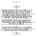
- FIG. 1 is flow chart explaining a method of manufacturing sintered iron ore applied with the present invention
- An essential point of the present invention is to provide a method of granulating a material for sintering using microparticulate dust and microparticulate sludge as main raw materials, and a method of manufacturing sintered iron ore, based on an original idea made on a method of granulation and a method of manufacturing sintered iron ore while taking sintering characteristics of microparticulate dust and microparticulate sludge different from those of iron ore powder into consideration.
- the present inventors basically analyzed intrinsic causes for incapability of the conventional technique of sintering iron ore, which cannot sinter a large amount of microparticulate dust and microparticulate sludge. Finally, the present inventors found out that the fine particles of the microparticulate dust and microparticulate sludge, in particular those having a grain size of 100 ⁇ m or smaller, are likely to fluidize by blown air in the process of sintering, and that such fluidization makes the sintering and binding difficult.
- microparticulate dust and microparticulate sludge are more difficult to be kept still, less likely to fuse and bind together even after being heated to sintering temperature, and is consequently less likely to form a sintered compact. It was made clear that, as a consequence, the sintering failure is ascribable to that they disseminate in a form of dust in the exhaust gas, rather than being grown into a solid sintered compact even if they should sinter.
- a basic condition for stable sintering of the microparticulate dust and microparticulate sludge is to prevent the fine particles from being kept in a free state.
- the raw material for sintering could be sintered anyhow even if it contains a small amount of fine particles, because they are incorporated into quasi-particles, despite some degradation in the yield and in the productivity in term of sintering performance.
- the raw material blend used at present is sintered generally under a content of 20% or around of iron ore particles as fine as of 1 mm or below.
- increase in the content of microparticulate dust and microparticulate sludge degrades the production speed, and the sintering will no more proceed if the content exceeds 30%.
- This phenomenon has been well known in general, wherein the present inventors found out that the causes for this failure reside in brittleness of the sintered compact of the particles formed in the process of sintering of the microparticulate dust and microparticulate sludge, based on fluidization phenomenon, or nearly under fluidization.
- the countermeasure therefor may be such as producing granulated grains to as strong enough as inhibiting the fluidization of the microparticulate dust and microparticulate sludge in the process of sintering, so that an experimental sintering was carried out while excluding ungranulated particles from the material for sintering.
- the present inventors also found out that sintering may stably be proceeded in some cases but may not in other cases, even with an effort of preventing the particles from being set free, and made extensive investigations to find causal factors. As a consequence, it was made clear that the state of production of molten liquid in the process of sintering should be controlled as being adapted to the fusing characteristics of the microparticulate dust and microparticulate sludge, in view of stable sintering.
- microparticulate dust and microparticulate sludge are likely to fuse in the process of sintering, so that an aggregate only composed of the microparticulate dust and microparticulate sludge may melt down at a time, when it reaches a certain high temperature, so that it is principally difficult to form and sustain a porous sintered compact which is a proper form of sinter product.
- the molten liquid surround the surface of the grains, the coarse grains bind with each other using the molten liquid as a binder, and thereby the sintered compact is gradually formed in turn as the sintering reaction proceeds.
- the coke breeze contained in the raw material keeps to combust under ventilation during sintering, so that current system of sintering iron ore powder, allowing the sintering to proceed with the aid of this heat, cannot maintain the reaction unless the porous compact body is formed while ensuring therein formation of through-pores for ventilation.
- the molten liquid fills up voids between the coarse grains so as to choke up the ventilation pores, and the sintering reaction no more proceeds. Therefore, it has been well known that control of the molten liquid is an essential point in the sintering operation.
- microparticulate dust and microparticulate sludge may be more likely to reduce the ratio of coarse particles which form the nucleus, to fill up the_gaps between the coarse grains, and to cause choking-up of the ventilation pores if the raw material tends to fuse at a time by its nature.
- the present inventors found out that sintering of the entire microparticulate dust and microparticulate sludge only by themselves are difficult, that the sintering may be stabilized only when the raw material blend contains coarse grains of 2 mm or larger to as much as 20% or more, and that, at the same time, some original idea on combustion control of cokes may be necessary in order to control production of the molten liquid.
- the nucleus-forming coarse grains are contained relatively a large amount in the raw material blend for sintering used for iron ore sintering, but increase in the nucleus-forming material conversely decreases the ratio of blending of the microparticulate dust and microparticulate sludge which increase use is target of the present invention.
- Production of the molten liquid in the process of sintering, induced by combustion heat of the cokes, may be controllable to a certain extent by the amount of addition of cokes, but may be controllable also by alignment of cokes in granulated grains, which is another measure for combustion control of cokes.
- One known technique in this field is a cokes interior/exterior technique making distribution of cokes differed between the inside and outside of the granulated grains.
- the amount of cokes may preferably be reduced as possible when the microparticulate dust and microparticulate sludge are granulated, because the coke breeze acts to lower the strength of grains in the process of granulation.
- the present inventors found out that it is necessary, for stable sintering, to suppress the amount of the interior cokes, under the interior/exterior distribution, to as much as one-third or less of the total amount of addition of coke breeze.
- the total amount of microparticulate dust and microparticulate sludge, added with a part of cokes (one-third or less of the total amount of coke breeze), are granulated by vibration kneading granulation, and the granulation is continued by adding the residual amount (two-thirds or more of the total amount of coke breeze) of cokes to the granulated grains so as to cover the surface thereof.
- raw material of the nucleus-forming coarse grain may be available returned sinter fines, or may be coarse grains of iron ores or lime stone.
- the coke breeze added as a fuel may be used as it were because it has conventionally been applied to sintering of iron ore, but a part of, or entire portion of which may be substituted by sludge produced in coke plants, or by blast furnace fly ash.
- sintering using the microparticulate dust and microparticulate sludge as the main raw material may be practiced by carrying out the processes shown in FIG. 1 .
- a raw material for sintering of 100% in total is blended so as to adjust iron-containing dust and/or sludge to 60% or more, and coarse grains having a grain size of 2 mm or larger to 20% or more on the weight basis, one-third or less of the total amount of addition of coke breeze as a fuel is added thereto, and the blend is kneaded and granulated using a vibration kneading granulator to thereby produce granulated grains (step S1).
- the ratio of blending herein is expressed on the dry weight basis.
- conventional iron-containing raw material for sintering such as iron ore powder, returned sinter fines and so forth, may be used.
- step S2 the residual portion of the total amount of addition of coke breeze is added to the granulated grains granulated in step S1 in the above, and the blend is subjected to exterior coating granulation using a rolling type granulator (step S2).
- step S3 The raw material for sintering, granulated by the granulation processes in steps S1, S2 described in the above, is sieved, and a fraction having a grain size of 1 mm or larger is used for sintering (step S3).
- stable sintering using the microparticulate dust and microparticulate sludge as main raw materials may be realized, by keeping the ratio of content of the nucleus-forming material in the raw material blend for sintering within a certain level, by carrying out cokes interior/exterior granulation while keeping the ratio of interior/exterior cokes at a certain condition, and by using only strong granulated grains containing no fraction having a grain size of 1 mm or smaller.
- sintered iron ore is now producible with high efficiency making use of the conventional facility, by using the microparticulate dust and microparticulate sludge produced as by-product in ironworks, extremely small in grain size, hard to granulate and hard to sinter, which are intrinsically different from sintering characteristics of ordinal iron ore, and by sintering the raw material by a method of sintering completely different from the conventionally-adopted methods of sintering.
- microparticulate dust and microparticulate sludge may contain impurities allowing manufacturing of sintered iron ore, but some may obstruct sustenance of stable production of sintered iron ore.
- zinc contained therein may form zinc white and may vaporize into the exhaust gas in the process of sintering, and may clog grate, or may adhere on an exhaust pipe, a dust precipitator or a blower, to thereby obstruct proceeding of operation.
- the alkali metals contained therein may not only degrade the dust collection efficiency of electric precipitator, but may also be causative of increase in the amount of emission of suspended particles through a chimney out into the air, and may therefore not be adoptable as the raw material for sintering.
- the oils contained therein may be causative of sudden combustion of an electric dust precipitator, and may be causative of adhesion of uncombusted oils onto the blower, so that the oils may be adoptable only to as much as a certain limited amount.
- the present inventors went into through investigations to solve the above-described problems, and finally reached a method capable of sintering a large amount of particulate dust and microparticulate sludge containing impurities, which could have not been used up to a large amount by the conventional method of sintering. The details will be described below.
- the sintering machine has a downdraft configuration, having the dust precipitator and the suction blower arranged in the exhaust system, and this may be causative of failure.
- the method of sintering may need a mechanism in which the exhaust system is provided independently from the grate, blower and so forth, so as to protect the individual facilities from various failures ascribable to the impurities in the exhaust gas.
- the updraft sintering is a method by which sintering is proceeded while introducing the air compressed by the blower in an air box under pallet of the sintering machine, and blowing, under pressure, the air up through the grate of the pallets bottom.
- the exhaust gas dissipates from the top surface of the pallets of the sintering machine, so that impurities such as zinc, alkali, uncombusted oils and so forth, even if contained therein, will never be brought into contact with the grate nor the blower, inducing no failures.
- a device removing these impurities may also be provided as being brought into direct contact with the exhaust gas system, by which the impurities may efficiently be removed.
- updraft sintering machines generally have a straight-type strand, wherein movable pallets and a strand frame are brought into contact on a rail at mechanical sliding portions while ensuring only a limited degree of air-tightness, causing a considerable air leakage and noise.
- the air leakage is also causative of unnecessary consumption of electric energy of the blower.
- the strand is configured so as to allow the pallets P to move in an endless manner. Because the route of return pallets lies below the strand, the eaves height of facility becomes large, and not only increases costs of facility, but also makes the machine incapable of suppressing dust. Since the pallets P tends to cause heavy material fatigue under repetitive heating load, a steel of expensive quality is used therefor.
- the sintering machine In order to configure a sintering machine solved in the above-described problems, small in environmental load, and suppressed in costs of facility and operation, it may be necessary from the view point of mechanism that the sintering machine would have no return pallets.
- the sintering machine may be configured as rotary-hearth type as schematically shown in FIG. 2A , by which the return pallets may be omissible, and the air box and the pallets P and the frame may be integrated. Accordingly, the air leakage may completely be avoidable, and extremely clean sintering as compared with the conventional sintering machine, completely suppressed in dust generation from the return pallets, may be realized.
- the rotary-hearth sintering machine is suitable as a sintering machine disusing the return pallets, and may be applicable both to the downdraft sintering and the updraft sintering. Sintering using, in particular, the microparticulate dust and microparticulate sludge as the main raw materials has suffered from heavy dust generation, and large air leakage due to increased ventilation resistance, thereby the conventional sintering machine having the return pallets has been limited in performance.
- adoption of the rotary- hearth system to the method using the microparticulate dust and microparticulate sludge as main materials may be effective, and may realize sintering suppressed in problematic dust generation and noise from the sintering machine, moderated in the environmental load, lowered in the cost for facility, reduced in the air leakage, and reduced in the unit consumption of electricity.
- the rotating pallets and a stationary exhaust gas system may be sealed using a water-seal device, and thereby the exhaust gas may be confined (see Patent Document 3).
- Adoption of this technique allows simple operation of exhaust gas processing, because the exhaust gas system thereof has no blower provided therein, unlike the downdraft sintering system.
- Adoption of this technique is extremely effective in particular to treatment of exhaust gas generated from sintering of microparticulate dust and microparticulate sludge containing impurities such as zinc oxide, alkali metals, uncombusted oils and so forth.
- One hundred percent in total of a raw material to be sintered was made up by 80% of LD converter dust, and 20% of coarse returned sinter fines.
- One percent (percentage (dry weight) assuming the amount of raw material to be sintered as 100) of blast furnace secondary fly ash was externally added thereto as a fuel, the blend was kneaded and granulated for 4 minutes using a vibration kneading granulator, further added with 3% (percentage (dry weight) assuming the amount of raw material to be sintered as 100) of blast furnace secondary fly ash, and subjected to rolling type granulation using a pan pelletizer.
- the granulated grains were then allowed to pass through a 3-mm-mesh vibration screen device, and those of 1 mm or larger were charged into a rotary-hearth sintering machine for updraft sintering. Since the grains contain zinc dust, the portion between the exhaust gas system and the pallets of the sintering machine was configured by a water-seal closed structure, coarse dust in the exhaust gas was then removed using a cyclone dust collector, followed by rapid cooling. Zinc oxide is then recovered using a zinc oxide collector, and the exhaust gas was emitted out into the air after dust removal using a bag-filter dust collector.
- One hundred percent in total of a raw material to be sintered was made up by 35% of oil-containing sludge, 45% of lime sludge, and 20% of coarse return fines. Three percent (percentage (dry weight) assuming the amount of raw material to be sintered as 100) of coke breeze was externally added thereto as a fuel, the blend was kneaded and granulated for 4 minutes using a vibration kneading granulator, further added with 6% (percentage (dry weight) assuming the amount of raw material to be sintered as 100) of coke breeze, and subjected to rolling type granulation using a pan pelletizer.
- Granulated grains of 1 mm or larger were collected through a vibration screen device, and then subjected to updraft sintering using a rotary-hearth sintering machine.
- the portion between the exhaust gas system and the pallets of the sintering machine was configured by a water-seal closed structure, coarse dust in the exhaust gas was then removed using a cyclone dust collector, and the exhaust gas was emitted out into the air after cleaned through a porous activated cokes packed layer.
- One hundred percent in total of a raw material to be sintered was made up by 45% of iron-containing dust 45%, 15% of iron-containing sludge, 5% of waste powder from iron ore, and 25% of return fines.
- One-and-a-half percent (percentage (dry weight) assuming the amount of raw material to be sintered as 100) of coke breeze was externally added thereto as a fuel, the blend was kneaded and granulated for 4 minutes using a vibration kneading granulator, further added with 4% (percentage (dry weight) assuming the amount of raw material to be sintered as 100) of coke breeze, and subjected to rolling type granulation using a pan pelletizer.
- Granulated grains of 1 mm or larger were collected through a vibration screen device, and then subjected to sintering using a downdraft DL (Dwight-Lloyd) sintering machine.
- One hundred percent of 5%-oil-containing sludge (fine particulate scale) was used as a raw material, and kneaded for 4 minutes using a vibration kneading granulator without being added with fuel, granulated grains of 1 mm or larger was collected through a vibration screen device, and allowed to sinter using a rotary-hearth updraft sintering machine.
- the exhaust gas containing dioxin was prevented from being emitted into the air by providing a water-seal closed structure to the portion between the exhaust gas system and the pallets of the sintering machine, and emitted through a porous activated coke packed layer after being removed with dust using a cyclone dust collector and a bag filter.
- the present invention enables high efficiency sintering using microparticulate dust and microparticulate sludge, which are small in grain size, less likely to be granulated, and difficult to sinter, as main raw materials, using a conventionally-used sintering facility.
Landscapes
- Engineering & Computer Science (AREA)
- Chemical & Material Sciences (AREA)
- Mechanical Engineering (AREA)
- Geology (AREA)
- General Life Sciences & Earth Sciences (AREA)
- Manufacturing & Machinery (AREA)
- Environmental & Geological Engineering (AREA)
- Materials Engineering (AREA)
- Life Sciences & Earth Sciences (AREA)
- Metallurgy (AREA)
- Organic Chemistry (AREA)
- Geochemistry & Mineralogy (AREA)
- Manufacture And Refinement Of Metals (AREA)
Applications Claiming Priority (1)
| Application Number | Priority Date | Filing Date | Title |
|---|---|---|---|
| PCT/JP2005/022205 WO2007063603A1 (ja) | 2005-12-02 | 2005-12-02 | 焼結原料の造粒方法及び焼結鉱製造方法 |
Publications (3)
| Publication Number | Publication Date |
|---|---|
| EP1961829A1 true EP1961829A1 (de) | 2008-08-27 |
| EP1961829A4 EP1961829A4 (de) | 2009-05-13 |
| EP1961829B1 EP1961829B1 (de) | 2010-04-28 |
Family
ID=38091944
Family Applications (1)
| Application Number | Title | Priority Date | Filing Date |
|---|---|---|---|
| EP20050811772 Expired - Lifetime EP1961829B1 (de) | 2005-12-02 | 2005-12-02 | Verfahren zum granulieren von sinterrohmaterial und verfahren zur herstellung von gesintertem erz |
Country Status (9)
| Country | Link |
|---|---|
| US (1) | US7875097B2 (de) |
| EP (1) | EP1961829B1 (de) |
| JP (1) | JP5021492B2 (de) |
| KR (1) | KR101018931B1 (de) |
| CN (1) | CN101321879B (de) |
| AT (1) | ATE466113T1 (de) |
| BR (1) | BRPI0520717A2 (de) |
| DE (1) | DE602005020994D1 (de) |
| WO (1) | WO2007063603A1 (de) |
Families Citing this family (16)
| Publication number | Priority date | Publication date | Assignee | Title |
|---|---|---|---|---|
| WO2010073718A1 (ja) * | 2008-12-26 | 2010-07-01 | 新日本製鐵株式会社 | X線ctを用いた焼結原料の造粒方法 |
| JP4840524B2 (ja) * | 2009-07-10 | 2011-12-21 | Jfeスチール株式会社 | 焼結用原料の製造方法 |
| JP5263431B2 (ja) * | 2011-07-28 | 2013-08-14 | Jfeスチール株式会社 | 焼結鉱の製造方法および製造設備ならびに粉原料投射装置 |
| CN102367513A (zh) * | 2011-10-28 | 2012-03-07 | 内蒙古包钢钢联股份有限公司 | 一种炼铁烧结矿脱除钾、钠的方法 |
| CN102417973A (zh) * | 2011-11-14 | 2012-04-18 | 山西太钢不锈钢股份有限公司 | 烧结燃料配加工艺及系统 |
| CN105308194B (zh) * | 2013-07-10 | 2018-11-13 | 杰富意钢铁株式会社 | 内包炭材料的烧结矿的制造方法 |
| JP6521259B2 (ja) * | 2016-06-30 | 2019-05-29 | Jfeスチール株式会社 | 焼結鉱製造用焼結原料の製造方法 |
| US10704119B2 (en) | 2017-05-04 | 2020-07-07 | Nu-Iron Technology, Llc. | Cokeless sinter blend compositions |
| CN109423555B (zh) * | 2017-08-23 | 2020-10-27 | 宝山钢铁股份有限公司 | 一种使用低硅铁精粉的铁矿石高效烧结方法 |
| JP6973627B2 (ja) | 2018-03-29 | 2021-12-01 | Jfeスチール株式会社 | 造粒物の製造方法および焼結鉱の製造方法 |
| CN108504375B (zh) * | 2018-06-01 | 2024-10-25 | 青岛华煤能源科技有限公司 | 冶金焦末成型生产设备及系统 |
| CN110079678B (zh) * | 2019-05-28 | 2020-11-06 | 中铝山东有限公司 | 一种回收利用二次铝灰中铝的方法 |
| CN110465538B (zh) * | 2019-08-19 | 2020-11-24 | 中南大学 | 一种高氯冶金废料和焚烧飞灰的预脱氯-烧结处理工艺 |
| CN113736495B (zh) * | 2021-08-31 | 2022-08-16 | 鄂尔多斯市环保投资有限公司 | 一种面向土壤生态修复的多源固体废弃物协同热处理装置 |
| WO2023161742A1 (en) * | 2022-02-23 | 2023-08-31 | Tata Steel Limited | A method of granulating a mxture for iron-ore sintering |
| CN115125400A (zh) * | 2022-06-23 | 2022-09-30 | 大连重工环保工程有限公司 | 一种高炉灰及烧结机头灰水洗提盐工艺 |
Family Cites Families (24)
| Publication number | Priority date | Publication date | Assignee | Title |
|---|---|---|---|---|
| US3732062A (en) * | 1972-01-20 | 1973-05-08 | J Porteus | Method of and apparatus for reducing air pollution in the thermal processing of ores and other materials |
| JPS4952111A (de) * | 1972-09-21 | 1974-05-21 | ||
| US3998703A (en) * | 1975-02-06 | 1976-12-21 | Salem Corporation | Method of treating materials on a rotary hearth |
| JPS5217321A (en) * | 1975-08-01 | 1977-02-09 | Seiichi Funaki | Process for recovering zinc contained in dust from steel manufacture |
| JPS5930775B2 (ja) * | 1977-04-05 | 1984-07-28 | 新日本製鐵株式会社 | 焼結原料の事前処理方法 |
| JPS59107036A (ja) * | 1982-12-10 | 1984-06-21 | Nippon Steel Corp | 焼結原料用非焼成ミニペレツト |
| JPH0778256B2 (ja) * | 1987-01-16 | 1995-08-23 | 日本鋼管株式会社 | 焼結用ミニペレツトの製造方法 |
| US5102586A (en) * | 1988-10-27 | 1992-04-07 | Kawasaki Steel Corporation | Agglomerating process of sinter mix and apparatus therefor |
| JPH03166321A (ja) | 1988-10-27 | 1991-07-18 | Kawasaki Steel Corp | 焼結原料の造粒方法及びその装置 |
| JPH089739B2 (ja) * | 1989-08-23 | 1996-01-31 | 日本鋼管株式会社 | 焼成塊成鉱の製造方法 |
| JPH0565548A (ja) * | 1991-09-05 | 1993-03-19 | Nippon Steel Corp | ダストの脱亜鉛を兼ねた焼結鉱製造方法 |
| JP2746030B2 (ja) * | 1992-12-14 | 1998-04-28 | 住友金属工業株式会社 | 焼結原料の事前処理方法 |
| JPH08193226A (ja) | 1995-01-17 | 1996-07-30 | Nippon Steel Corp | 製鋼湿ダストの塊成化における亜鉛回収方法および集塵フード |
| JP3709052B2 (ja) | 1997-06-05 | 2005-10-19 | 協材興業株式会社 | 含亜鉛製鉄ダストの脱亜鉛塊成化方法 |
| US6342089B1 (en) * | 1997-09-02 | 2002-01-29 | Mcgaa John R. | Direct reduced iron pellets |
| JP3781153B2 (ja) * | 1997-09-22 | 2006-05-31 | 株式会社 テツゲン | 製鉄ダスト等からの安価な還元鉄の製造方法 |
| JP3731361B2 (ja) * | 1998-12-25 | 2006-01-05 | Jfeスチール株式会社 | 焼結鉱の製造方法 |
| JP2000248320A (ja) | 1999-02-26 | 2000-09-12 | Nippon Steel Corp | 含亜鉛製鉄ダストの脱亜鉛塊成化方法 |
| JP4087982B2 (ja) * | 1999-04-05 | 2008-05-21 | 新日本製鐵株式会社 | 燃焼性に優れた焼結用原料の造粒方法 |
| WO2000074834A1 (en) * | 1999-06-07 | 2000-12-14 | Freund Industrial Co., Ltd. | Centrifugally rolling granulating device and method of treating powder and granular material using the device |
| JP3879408B2 (ja) * | 2001-01-31 | 2007-02-14 | Jfeスチール株式会社 | 焼結鉱の製造方法および焼結鉱 |
| CN1220782C (zh) * | 2002-11-18 | 2005-09-28 | 陈广军 | 用含铁尘泥生产的小球烧结矿及其工艺方法和专用的竖炉 |
| JP4241285B2 (ja) * | 2003-09-22 | 2009-03-18 | Jfeスチール株式会社 | 半還元焼結鉱の製造方法 |
| JP2005213593A (ja) * | 2004-01-29 | 2005-08-11 | Jfe Steel Kk | 半還元塊成鉱の製造方法 |
-
2005
- 2005-12-02 BR BRPI0520717-7A patent/BRPI0520717A2/pt not_active IP Right Cessation
- 2005-12-02 DE DE200560020994 patent/DE602005020994D1/de not_active Expired - Lifetime
- 2005-12-02 AT AT05811772T patent/ATE466113T1/de not_active IP Right Cessation
- 2005-12-02 JP JP2007547830A patent/JP5021492B2/ja not_active Expired - Lifetime
- 2005-12-02 EP EP20050811772 patent/EP1961829B1/de not_active Expired - Lifetime
- 2005-12-02 WO PCT/JP2005/022205 patent/WO2007063603A1/ja not_active Ceased
- 2005-12-02 US US12/085,913 patent/US7875097B2/en not_active Expired - Fee Related
- 2005-12-02 CN CN2005800522068A patent/CN101321879B/zh not_active Expired - Fee Related
- 2005-12-02 KR KR1020087016032A patent/KR101018931B1/ko not_active Expired - Fee Related
Also Published As
| Publication number | Publication date |
|---|---|
| WO2007063603A1 (ja) | 2007-06-07 |
| US7875097B2 (en) | 2011-01-25 |
| ATE466113T1 (de) | 2010-05-15 |
| JPWO2007063603A1 (ja) | 2009-05-07 |
| EP1961829B1 (de) | 2010-04-28 |
| KR20080074204A (ko) | 2008-08-12 |
| DE602005020994D1 (de) | 2010-06-10 |
| CN101321879B (zh) | 2010-06-09 |
| JP5021492B2 (ja) | 2012-09-05 |
| EP1961829A4 (de) | 2009-05-13 |
| CN101321879A (zh) | 2008-12-10 |
| KR101018931B1 (ko) | 2011-03-02 |
| US20090078088A1 (en) | 2009-03-26 |
| BRPI0520717A2 (pt) | 2009-07-14 |
Similar Documents
| Publication | Publication Date | Title |
|---|---|---|
| EP1961829B1 (de) | Verfahren zum granulieren von sinterrohmaterial und verfahren zur herstellung von gesintertem erz | |
| Lu et al. | Iron ore sintering | |
| CN107419093B (zh) | 用于制造烧结矿的内包炭材料的造粒粒子及其制造方法、以及烧结矿的制造方法 | |
| RU2605409C2 (ru) | Системы и способы переработки остатков выхлопов сталеплавильного конвертера и изделия, производимые с их помощью | |
| JP2009185356A (ja) | 焼結鉱の製造方法 | |
| MX2008014933A (es) | Proceso para reciclaje de derivados portadores de hierro de la industria siderurgica, comprimidos obtenidos en ese proceso y uso de los mismos. | |
| JP2003213312A (ja) | 金属鉄の製法 | |
| JPH06330198A (ja) | ダスト中の亜鉛の回収方法 | |
| AU777336B2 (en) | Method for utilizing activated carbon powder recovered from exhaust sintering gas treating apparatus | |
| JP5168802B2 (ja) | 焼結鉱の製造方法 | |
| CN116829739B (zh) | 生铁制造方法 | |
| JP2003306723A (ja) | 高炉用焼結鉱の製造方法 | |
| JP2003277838A (ja) | 高炉用焼結原料に用いる高結晶水鉱石、高炉用焼結原料及びその製造方法 | |
| JP4830728B2 (ja) | 焼結鉱の製造方法 | |
| JP2005194543A (ja) | 半還元塊成鉱の製造方法 | |
| JPH11229007A (ja) | 竪型シャフトキュポラ・高炉・溶融炉法 | |
| JP2009221491A (ja) | 酸化物原料を含む硫化物原料の焼結方法 | |
| KR20190006006A (ko) | 탄재 내장 소결광의 제조 방법 | |
| WO2015092132A1 (en) | Method for exploiting dusts generated in a ferronickel process and sintered pellets produced by the method | |
| KR20260072123A (ko) | Cdq 더스트의 소결 연료화 방법 | |
| JP3881805B2 (ja) | 溶銑製造方法 | |
| Milosan | STUDY REGARDING TO THE RECYCLING OF METALLURGICAL WASTE | |
| Piñuela-Noval et al. | Iron Ore Agglomeration Technologies | |
| JPH10330853A (ja) | 非鉄金属製錬原料の焼結方法および装置 | |
| JP2020007576A (ja) | 炭材内装焼結鉱の製造方法及び製造設備 |
Legal Events
| Date | Code | Title | Description |
|---|---|---|---|
| PUAI | Public reference made under article 153(3) epc to a published international application that has entered the european phase |
Free format text: ORIGINAL CODE: 0009012 |
|
| 17P | Request for examination filed |
Effective date: 20080625 |
|
| AK | Designated contracting states |
Kind code of ref document: A1 Designated state(s): AT BE BG CH CY CZ DE DK EE ES FI FR GB GR HU IE IS IT LI LT LU LV MC NL PL PT RO SE SI SK TR |
|
| RIC1 | Information provided on ipc code assigned before grant |
Ipc: C22B 1/245 20060101ALI20090401BHEP Ipc: C22B 1/16 20060101AFI20070727BHEP Ipc: C22B 7/02 20060101ALI20090401BHEP Ipc: C22B 1/20 20060101ALI20090401BHEP |
|
| A4 | Supplementary search report drawn up and despatched |
Effective date: 20090409 |
|
| GRAP | Despatch of communication of intention to grant a patent |
Free format text: ORIGINAL CODE: EPIDOSNIGR1 |
|
| DAX | Request for extension of the european patent (deleted) | ||
| GRAS | Grant fee paid |
Free format text: ORIGINAL CODE: EPIDOSNIGR3 |
|
| GRAA | (expected) grant |
Free format text: ORIGINAL CODE: 0009210 |
|
| AK | Designated contracting states |
Kind code of ref document: B1 Designated state(s): AT BE BG CH CY CZ DE DK EE ES FI FR GB GR HU IE IS IT LI LT LU LV MC NL PL PT RO SE SI SK TR |
|
| REG | Reference to a national code |
Ref country code: GB Ref legal event code: FG4D |
|
| REG | Reference to a national code |
Ref country code: CH Ref legal event code: EP |
|
| REG | Reference to a national code |
Ref country code: IE Ref legal event code: FG4D |
|
| REF | Corresponds to: |
Ref document number: 602005020994 Country of ref document: DE Date of ref document: 20100610 Kind code of ref document: P |
|
| REG | Reference to a national code |
Ref country code: SE Ref legal event code: TRGR |
|
| REG | Reference to a national code |
Ref country code: NL Ref legal event code: T3 |
|
| LTIE | Lt: invalidation of european patent or patent extension |
Effective date: 20100428 |
|
| PG25 | Lapsed in a contracting state [announced via postgrant information from national office to epo] |
Ref country code: LT Free format text: LAPSE BECAUSE OF FAILURE TO SUBMIT A TRANSLATION OF THE DESCRIPTION OR TO PAY THE FEE WITHIN THE PRESCRIBED TIME-LIMIT Effective date: 20100428 Ref country code: ES Free format text: LAPSE BECAUSE OF FAILURE TO SUBMIT A TRANSLATION OF THE DESCRIPTION OR TO PAY THE FEE WITHIN THE PRESCRIBED TIME-LIMIT Effective date: 20100808 |
|
| PG25 | Lapsed in a contracting state [announced via postgrant information from national office to epo] |
Ref country code: FI Free format text: LAPSE BECAUSE OF FAILURE TO SUBMIT A TRANSLATION OF THE DESCRIPTION OR TO PAY THE FEE WITHIN THE PRESCRIBED TIME-LIMIT Effective date: 20100428 Ref country code: AT Free format text: LAPSE BECAUSE OF FAILURE TO SUBMIT A TRANSLATION OF THE DESCRIPTION OR TO PAY THE FEE WITHIN THE PRESCRIBED TIME-LIMIT Effective date: 20100428 Ref country code: SI Free format text: LAPSE BECAUSE OF FAILURE TO SUBMIT A TRANSLATION OF THE DESCRIPTION OR TO PAY THE FEE WITHIN THE PRESCRIBED TIME-LIMIT Effective date: 20100428 Ref country code: LV Free format text: LAPSE BECAUSE OF FAILURE TO SUBMIT A TRANSLATION OF THE DESCRIPTION OR TO PAY THE FEE WITHIN THE PRESCRIBED TIME-LIMIT Effective date: 20100428 Ref country code: IS Free format text: LAPSE BECAUSE OF FAILURE TO SUBMIT A TRANSLATION OF THE DESCRIPTION OR TO PAY THE FEE WITHIN THE PRESCRIBED TIME-LIMIT Effective date: 20100828 |
|
| PG25 | Lapsed in a contracting state [announced via postgrant information from national office to epo] |
Ref country code: PL Free format text: LAPSE BECAUSE OF FAILURE TO SUBMIT A TRANSLATION OF THE DESCRIPTION OR TO PAY THE FEE WITHIN THE PRESCRIBED TIME-LIMIT Effective date: 20100428 Ref country code: GR Free format text: LAPSE BECAUSE OF FAILURE TO SUBMIT A TRANSLATION OF THE DESCRIPTION OR TO PAY THE FEE WITHIN THE PRESCRIBED TIME-LIMIT Effective date: 20100729 Ref country code: CY Free format text: LAPSE BECAUSE OF FAILURE TO SUBMIT A TRANSLATION OF THE DESCRIPTION OR TO PAY THE FEE WITHIN THE PRESCRIBED TIME-LIMIT Effective date: 20100602 |
|
| PG25 | Lapsed in a contracting state [announced via postgrant information from national office to epo] |
Ref country code: PT Free format text: LAPSE BECAUSE OF FAILURE TO SUBMIT A TRANSLATION OF THE DESCRIPTION OR TO PAY THE FEE WITHIN THE PRESCRIBED TIME-LIMIT Effective date: 20100830 Ref country code: EE Free format text: LAPSE BECAUSE OF FAILURE TO SUBMIT A TRANSLATION OF THE DESCRIPTION OR TO PAY THE FEE WITHIN THE PRESCRIBED TIME-LIMIT Effective date: 20100428 Ref country code: DK Free format text: LAPSE BECAUSE OF FAILURE TO SUBMIT A TRANSLATION OF THE DESCRIPTION OR TO PAY THE FEE WITHIN THE PRESCRIBED TIME-LIMIT Effective date: 20100428 |
|
| PG25 | Lapsed in a contracting state [announced via postgrant information from national office to epo] |
Ref country code: SK Free format text: LAPSE BECAUSE OF FAILURE TO SUBMIT A TRANSLATION OF THE DESCRIPTION OR TO PAY THE FEE WITHIN THE PRESCRIBED TIME-LIMIT Effective date: 20100428 Ref country code: CZ Free format text: LAPSE BECAUSE OF FAILURE TO SUBMIT A TRANSLATION OF THE DESCRIPTION OR TO PAY THE FEE WITHIN THE PRESCRIBED TIME-LIMIT Effective date: 20100428 Ref country code: RO Free format text: LAPSE BECAUSE OF FAILURE TO SUBMIT A TRANSLATION OF THE DESCRIPTION OR TO PAY THE FEE WITHIN THE PRESCRIBED TIME-LIMIT Effective date: 20100428 |
|
| PLBE | No opposition filed within time limit |
Free format text: ORIGINAL CODE: 0009261 |
|
| STAA | Information on the status of an ep patent application or granted ep patent |
Free format text: STATUS: NO OPPOSITION FILED WITHIN TIME LIMIT |
|
| PG25 | Lapsed in a contracting state [announced via postgrant information from national office to epo] |
Ref country code: IT Free format text: LAPSE BECAUSE OF FAILURE TO SUBMIT A TRANSLATION OF THE DESCRIPTION OR TO PAY THE FEE WITHIN THE PRESCRIBED TIME-LIMIT Effective date: 20100428 |
|
| 26N | No opposition filed |
Effective date: 20110131 |
|
| PG25 | Lapsed in a contracting state [announced via postgrant information from national office to epo] |
Ref country code: MC Free format text: LAPSE BECAUSE OF NON-PAYMENT OF DUE FEES Effective date: 20101231 |
|
| REG | Reference to a national code |
Ref country code: CH Ref legal event code: PL |
|
| PG25 | Lapsed in a contracting state [announced via postgrant information from national office to epo] |
Ref country code: CH Free format text: LAPSE BECAUSE OF NON-PAYMENT OF DUE FEES Effective date: 20101231 Ref country code: LI Free format text: LAPSE BECAUSE OF NON-PAYMENT OF DUE FEES Effective date: 20101231 Ref country code: IE Free format text: LAPSE BECAUSE OF NON-PAYMENT OF DUE FEES Effective date: 20101202 |
|
| PG25 | Lapsed in a contracting state [announced via postgrant information from national office to epo] |
Ref country code: HU Free format text: LAPSE BECAUSE OF FAILURE TO SUBMIT A TRANSLATION OF THE DESCRIPTION OR TO PAY THE FEE WITHIN THE PRESCRIBED TIME-LIMIT Effective date: 20101029 Ref country code: BG Free format text: LAPSE BECAUSE OF FAILURE TO SUBMIT A TRANSLATION OF THE DESCRIPTION OR TO PAY THE FEE WITHIN THE PRESCRIBED TIME-LIMIT Effective date: 20100428 |
|
| PG25 | Lapsed in a contracting state [announced via postgrant information from national office to epo] |
Ref country code: TR Free format text: LAPSE BECAUSE OF FAILURE TO SUBMIT A TRANSLATION OF THE DESCRIPTION OR TO PAY THE FEE WITHIN THE PRESCRIBED TIME-LIMIT Effective date: 20100428 |
|
| PG25 | Lapsed in a contracting state [announced via postgrant information from national office to epo] |
Ref country code: BG Free format text: LAPSE BECAUSE OF FAILURE TO SUBMIT A TRANSLATION OF THE DESCRIPTION OR TO PAY THE FEE WITHIN THE PRESCRIBED TIME-LIMIT Effective date: 20100728 |
|
| PGFP | Annual fee paid to national office [announced via postgrant information from national office to epo] |
Ref country code: LU Payment date: 20141218 Year of fee payment: 10 |
|
| PGFP | Annual fee paid to national office [announced via postgrant information from national office to epo] |
Ref country code: BE Payment date: 20141218 Year of fee payment: 10 |
|
| REG | Reference to a national code |
Ref country code: FR Ref legal event code: PLFP Year of fee payment: 11 |
|
| PGFP | Annual fee paid to national office [announced via postgrant information from national office to epo] |
Ref country code: GB Payment date: 20151229 Year of fee payment: 11 |
|
| PGFP | Annual fee paid to national office [announced via postgrant information from national office to epo] |
Ref country code: NL Payment date: 20151217 Year of fee payment: 11 |
|
| PG25 | Lapsed in a contracting state [announced via postgrant information from national office to epo] |
Ref country code: BE Free format text: LAPSE BECAUSE OF NON-PAYMENT OF DUE FEES Effective date: 20151231 |
|
| PG25 | Lapsed in a contracting state [announced via postgrant information from national office to epo] |
Ref country code: LU Free format text: LAPSE BECAUSE OF NON-PAYMENT OF DUE FEES Effective date: 20151202 |
|
| REG | Reference to a national code |
Ref country code: FR Ref legal event code: PLFP Year of fee payment: 12 |
|
| REG | Reference to a national code |
Ref country code: NL Ref legal event code: MM Effective date: 20170101 |
|
| GBPC | Gb: european patent ceased through non-payment of renewal fee |
Effective date: 20161202 |
|
| PG25 | Lapsed in a contracting state [announced via postgrant information from national office to epo] |
Ref country code: NL Free format text: LAPSE BECAUSE OF NON-PAYMENT OF DUE FEES Effective date: 20170101 |
|
| PG25 | Lapsed in a contracting state [announced via postgrant information from national office to epo] |
Ref country code: GB Free format text: LAPSE BECAUSE OF NON-PAYMENT OF DUE FEES Effective date: 20161202 |
|
| REG | Reference to a national code |
Ref country code: FR Ref legal event code: PLFP Year of fee payment: 13 |
|
| PGFP | Annual fee paid to national office [announced via postgrant information from national office to epo] |
Ref country code: SE Payment date: 20171214 Year of fee payment: 13 |
|
| REG | Reference to a national code |
Ref country code: SE Ref legal event code: EUG |
|
| PG25 | Lapsed in a contracting state [announced via postgrant information from national office to epo] |
Ref country code: SE Free format text: LAPSE BECAUSE OF NON-PAYMENT OF DUE FEES Effective date: 20181203 |
|
| PGFP | Annual fee paid to national office [announced via postgrant information from national office to epo] |
Ref country code: FR Payment date: 20191212 Year of fee payment: 15 |
|
| PG25 | Lapsed in a contracting state [announced via postgrant information from national office to epo] |
Ref country code: FR Free format text: LAPSE BECAUSE OF NON-PAYMENT OF DUE FEES Effective date: 20201231 |
|
| PGFP | Annual fee paid to national office [announced via postgrant information from national office to epo] |
Ref country code: DE Payment date: 20211229 Year of fee payment: 17 |
|
| REG | Reference to a national code |
Ref country code: DE Ref legal event code: R119 Ref document number: 602005020994 Country of ref document: DE |
|
| PG25 | Lapsed in a contracting state [announced via postgrant information from national office to epo] |
Ref country code: DE Free format text: LAPSE BECAUSE OF NON-PAYMENT OF DUE FEES Effective date: 20230701 |