EP1961867B1 - A method of building a monolithic underground concrete structure - Google Patents
A method of building a monolithic underground concrete structure Download PDFInfo
- Publication number
- EP1961867B1 EP1961867B1 EP20080151665 EP08151665A EP1961867B1 EP 1961867 B1 EP1961867 B1 EP 1961867B1 EP 20080151665 EP20080151665 EP 20080151665 EP 08151665 A EP08151665 A EP 08151665A EP 1961867 B1 EP1961867 B1 EP 1961867B1
- Authority
- EP
- European Patent Office
- Prior art keywords
- columnar
- blocks
- tertiary
- primary
- columns
- Prior art date
- Legal status (The legal status is an assumption and is not a legal conclusion. Google has not performed a legal analysis and makes no representation as to the accuracy of the status listed.)
- Active
Links
Images

Classifications
-
- E—FIXED CONSTRUCTIONS
- E02—HYDRAULIC ENGINEERING; FOUNDATIONS; SOIL SHIFTING
- E02D—FOUNDATIONS; EXCAVATIONS; EMBANKMENTS; UNDERGROUND OR UNDERWATER STRUCTURES
- E02D5/00—Bulkheads, piles, or other structural elements specially adapted to foundation engineering
- E02D5/22—Piles
- E02D5/34—Concrete or concrete-like piles cast in position ; Apparatus for making same
- E02D5/46—Concrete or concrete-like piles cast in position ; Apparatus for making same making in situ by forcing bonding agents into gravel fillings or the soil
-
- E—FIXED CONSTRUCTIONS
- E02—HYDRAULIC ENGINEERING; FOUNDATIONS; SOIL SHIFTING
- E02D—FOUNDATIONS; EXCAVATIONS; EMBANKMENTS; UNDERGROUND OR UNDERWATER STRUCTURES
- E02D19/00—Keeping dry foundation sites or other areas in the ground
- E02D19/06—Restraining of underground water
- E02D19/12—Restraining of underground water by damming or interrupting the passage of underground water
- E02D19/18—Restraining of underground water by damming or interrupting the passage of underground water by making use of sealing aprons, e.g. diaphragms made from bituminous or clay material
-
- E—FIXED CONSTRUCTIONS
- E02—HYDRAULIC ENGINEERING; FOUNDATIONS; SOIL SHIFTING
- E02D—FOUNDATIONS; EXCAVATIONS; EMBANKMENTS; UNDERGROUND OR UNDERWATER STRUCTURES
- E02D27/00—Foundations as substructures
- E02D27/26—Compacting soil locally before forming foundations; Construction of foundation structures by forcing binding substances into gravel fillings
-
- E—FIXED CONSTRUCTIONS
- E02—HYDRAULIC ENGINEERING; FOUNDATIONS; SOIL SHIFTING
- E02D—FOUNDATIONS; EXCAVATIONS; EMBANKMENTS; UNDERGROUND OR UNDERWATER STRUCTURES
- E02D29/00—Independent underground or underwater structures; Retaining walls
- E02D29/16—Arrangement or construction of joints in foundation structures
-
- E—FIXED CONSTRUCTIONS
- E02—HYDRAULIC ENGINEERING; FOUNDATIONS; SOIL SHIFTING
- E02D—FOUNDATIONS; EXCAVATIONS; EMBANKMENTS; UNDERGROUND OR UNDERWATER STRUCTURES
- E02D5/00—Bulkheads, piles, or other structural elements specially adapted to foundation engineering
- E02D5/22—Piles
- E02D5/64—Repairing piles
Definitions
- the present invention relates to a method of constructing a monolithic underground artificial conglomerate structure for the purposes of consolidation and/or waterproofing.
- jet grouting In order to consolidate volumes of soil having a clearly defined geometry, methods known as "jet grouting" are used to form columnar artificial conglomerate structures, spaced apart from each other, around the portion of soil to be excavated. These methods are based on the mixing of particles of the soil itself with binders, usually cement mixtures, which are injected at high pressure through small radial nozzles formed in the proximity of the lower end of a tubular shaft which is rotated and raised towards the surface. The jets of binder disgregate and are mixed with the surrounding soil, thus creating a column of conglomerate which, when hardened, consolidates the soil. The disgregating efficiency of the jet can be increased by the addition of injected water and/or pressurized air.
- the object of the present invention is to propose a method of constructing monolithic artificial conglomerate structures which extend continuously in the soil.
- the aim is to form a stable waterproof structure, regardless of any non-uniformity of the soil and the inevitable deviations from the vertical of the columnar formations created by jet grouting.
- the equipment and methods for jet grouting are well known in the field of soil mechanics, and therefore they will not be described or illustrated in detail in this document.
- the shape, dimensions and function of the underground structure can vary according to requirements, and are not to be interpreted as limiting the scope of the patent in any way.
- the invention can be used for constructing a substantially tubular shell of consolidated and waterproofed soil which is to be constructed around a portion of soil in which a tunnel is to be excavated.
- a first set of artificial conglomerate blocks P is formed, these blocks being positioned in a predetermined reticular geometrical layout.
- These blocks referred to hereafter as primary columns, are vertical columnar elements whose height depends on the vertical thickness of the structure to be constructed.
- the primary columns P are parallel to each other and spaced apart from each other.
- the cells have a reticular layout with a triangular or hexagonal (honeycomb) mesh, in which the central axes of the primary columns P are positioned at the vertices of an equilateral triangle or at the non-consecutive vertices of a regular hexagon.
- a jet grouting method is used to form a second set of columnar blocks or parallel secondary columns S of artificial conglomerate.
- Each secondary column S is interposed between, and securely joins, two primary columns P formed previously, causing the combined primary and secondary columns of each cell to form a closed ring structure.
- the secondary columns have their respective axes positioned on the vertices of the hexagon alternating with the vertices on which the axes of the primary columns are located.
- a tertiary column T is formed, again by jet grouting, in the central space formed between the primary and secondary columns of each cell.
- the secondary columns Because of the hardening of the primary columns, which theoretically have a circular cross section, the secondary columns have a cross section with concave lobes along their surfaces adjoining the primary columns.
- the tertiary columns have a cross section of multiple-lobed shape with concave lobes along their surfaces adjoining the primary and secondary columns.
- all the columns of each type are formed with a constant jet grouting treatment intensity for each metre of column, for example with a jet having a flow rate of 300-320 1/min. at a pressure of 400-420 bars.
- the different shapes of the primary, secondary and tertiary columns correspond to different cross-sectional areas, this area in the secondary columns being about 60% of that of the primary columns, while in the tertiary columns it is about 30% of the area of the primary columns. Consequently, the specific energy per cubic metre of consolidated soil for the secondary columns is 160% of that of the primary columns, while it is 300% for the tertiary columns, assuming that the same jet grouting parameters are maintained for each linear metre of column.
- the tertiary columns are formed in the spaces enclosed by the primary and secondary columns, and are therefore protected from any negative external effects such as movements of the water-table and the presence of soils with increasing permeability which could lead to losses of cement mixture from the outside of the cell.
- the primary and secondary columns of each cell are also primary and secondary columns of contiguous cells.
- the formation of the tertiary columns improves the overall strength by compensating for any deviations from the parallel arrangement of the previously formed columns.
- the tertiary columns closely bind all the surrounding columns, by which they are also protected, and therefore the cement mixture which is injected, or "jetted", scarifies and penetrates the surfaces of the primary and secondary columns facing the centre of the cell.
- the formation of the tertiary column remedies any untreated areas.
- an area Z of soil which has not been treated during the formation of the secondary column S because of a body A (for example a rock or a tree trunk) is subsequently reached by the cement mixture when the tertiary column T is formed.
- a body A for example a rock or a tree trunk
- the formation of the tertiary column takes place in the centre of a "well" formed by the primary and secondary columns of the cell, which confine the jetting mixture without making it flow out. This confining or sealing effect is multiplied as the operation proceeds.
- the mutual "grooving" of the columns opposes their separation when the finished structure is stressed by a load, for example when part of the soil at one side of the structure is excavated.
- the structure is completed by forming more or less numerous groups of cells simultaneously or in succession, until the whole area specified by the design is covered, thus providing a continuous monolithic structure.
- the closed cells can be formed with some columns vertical and some inclined, or with all the columns inclined.
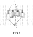
- caps C of substantially disc-like shape. These caps are widened upper and/or lower extensions of the tertiary columns T, and extend transversely so as to cover, at least partially, the ends of the primary and secondary columns which surround the tertiary columns concerned.
- the caps C are formed by increasing one or more of the jetting parameters for the tertiary columns when the jetting nozzle has risen above the tops of the primary and secondary columns.
- the larger diameter of the cap can be obtained, for example, by increasing the pressure or the flow rate of the mixture, or by retarding the rising movement of the hollow shaft (not shown) which carries the cement mixture injection nozzles.
- the caps C can be formed at both the bottoms and the tops of the primary and secondary columns, in other words at both ends of the structure.
- the caps can be formed on only one end of the structure, for example over the tops of the columns.
- the diameter of the caps depends on the intensity of the jetting. As shown in Figure 6 , the diameter can be specified in such a way that the caps of the contiguous closed cells are tangential to each other. Thus the vertical contact surfaces between the columns P, S and T are sealed by the caps of the tertiary columns and cannot form preferential paths for the flow of water through the structure.
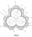
- caps C as shown in Figures 7 and 8 , are extended in such a way that they are joined securely to each other, penetrating into each other and forming a continuous monolithic layer or slab of conglomerate which covers the underlying structure comprising the primary and secondary columns.
- the superimposed layer formed by the caps C seals off all possible paths for the infiltration of water and also greatly reinforces the overall rigidity of the structure.
Landscapes
- Engineering & Computer Science (AREA)
- Life Sciences & Earth Sciences (AREA)
- Structural Engineering (AREA)
- General Engineering & Computer Science (AREA)
- Paleontology (AREA)
- Civil Engineering (AREA)
- Mining & Mineral Resources (AREA)
- General Life Sciences & Earth Sciences (AREA)
- Environmental & Geological Engineering (AREA)
- Hydrology & Water Resources (AREA)
- Lining And Supports For Tunnels (AREA)
- Consolidation Of Soil By Introduction Of Solidifying Substances Into Soil (AREA)
- Underground Structures, Protecting, Testing And Restoring Foundations (AREA)
Applications Claiming Priority (1)
| Application Number | Priority Date | Filing Date | Title |
|---|---|---|---|
| ITTO20070127 ITTO20070127A1 (it) | 2007-02-22 | 2007-02-22 | Procedimento per costruire una struttura interrata monolitica di conglomerato artificiale. |
Publications (3)
| Publication Number | Publication Date |
|---|---|
| EP1961867A2 EP1961867A2 (en) | 2008-08-27 |
| EP1961867A3 EP1961867A3 (en) | 2012-05-30 |
| EP1961867B1 true EP1961867B1 (en) | 2013-07-03 |
Family
ID=39402763
Family Applications (1)
| Application Number | Title | Priority Date | Filing Date |
|---|---|---|---|
| EP20080151665 Active EP1961867B1 (en) | 2007-02-22 | 2008-02-20 | A method of building a monolithic underground concrete structure |
Country Status (2)
| Country | Link |
|---|---|
| EP (1) | EP1961867B1 (it) |
| IT (1) | ITTO20070127A1 (it) |
Families Citing this family (2)
| Publication number | Priority date | Publication date | Assignee | Title |
|---|---|---|---|---|
| CN104631480B (zh) * | 2014-12-26 | 2016-07-20 | 中铁二局工程有限公司 | 采用高压旋喷桩机进行深基坑止水帷幕施工的方法 |
| CN108612119A (zh) * | 2018-04-23 | 2018-10-02 | 中国水利水电第九工程局有限公司 | 一种高压旋喷防渗帷幕的施工方法 |
Family Cites Families (4)
| Publication number | Priority date | Publication date | Assignee | Title |
|---|---|---|---|---|
| GB2301134B (en) * | 1995-05-20 | 1998-03-25 | May Gurney | In-situ treatment of contaminated land using modified piling auger |
| EP1045073A1 (en) * | 1999-04-15 | 2000-10-18 | TREVI S.p.A. | An excavation tool and a method for forming a column of consolidated soil |
| DE19953819A1 (de) * | 1999-11-09 | 2001-05-10 | Zueblin Ag | Kombination aus HDI-Verfahren und Bodenvereisung zur Herstellung von Dichtwänden |
| BE1016154A6 (nl) * | 2003-10-14 | 2006-04-04 | Denys Nv | Werkwijze voor het realiseren van grondkolommen door diepvermenging van bindmiddelen in de grond. |
-
2007
- 2007-02-22 IT ITTO20070127 patent/ITTO20070127A1/it unknown
-
2008
- 2008-02-20 EP EP20080151665 patent/EP1961867B1/en active Active
Also Published As
| Publication number | Publication date |
|---|---|
| ITTO20070127A1 (it) | 2008-08-23 |
| EP1961867A2 (en) | 2008-08-27 |
| EP1961867A3 (en) | 2012-05-30 |
Similar Documents
| Publication | Publication Date | Title |
|---|---|---|
| US3421326A (en) | Constructional works | |
| US11674393B2 (en) | Method for constructing dam inside dump of inner-dump strip mine | |
| CN102767189A (zh) | 一种设置桩承台基础及其施工方法 | |
| CN105155554A (zh) | 一种拱形支护体系的深基坑 | |
| KR20140121119A (ko) | 연결근이 일체로 구성된 고강도 pc부재용 phc파일, phc파일 제조방법 및 이를 이용한 지하 합벽 시공방법 | |
| KR101739657B1 (ko) | 복합댐 및 그 시공방법 | |
| CN116335757B (zh) | 一种负泊松比结构充填挡墙及其施工方法 | |
| CN105332380B (zh) | 一种地下建筑的换撑结构及方法 | |
| CN111910630A (zh) | 一种锚索结构及锚索框架梁施工方法 | |
| CN102720136B (zh) | 一种便道、便桥和承台筑岛围堰施工方法 | |
| EP1961867B1 (en) | A method of building a monolithic underground concrete structure | |
| KR100947627B1 (ko) | 터널의 강화 그라우팅구조 및 이를 적용한 터널 시공방법 | |
| CN109555148B (zh) | 岩溶地基处理跨越较大溶腔的方法及其组合桩板结构 | |
| CN106522982A (zh) | 富水未固结地层抗浮抗沉抗水压减震隧道施工方法 | |
| CN102704499B (zh) | 一种错台竹木梯格构梁绿色固坡防护方法 | |
| CN117071535A (zh) | 可减震减压的废旧轮胎加筋透水混凝土桩及其施工工艺 | |
| CN103215950A (zh) | 回填区桩基接长施工方法 | |
| JP2013147805A (ja) | 液状化対策方法及び構造 | |
| CN111236996B (zh) | 岩质地层超大跨隧洞高边坡洞口支护结构及其施工方法 | |
| JP2000136541A (ja) | 液状化防止工法 | |
| CN218843065U (zh) | 一种用于基坑围护的斜向支撑桩结构 | |
| KR20170035321A (ko) | 하향식 다단계 흙막이 시공방법 및 이를 통해 시공된 흙막이 구조체 | |
| CN110512620A (zh) | 大堤边坡开挖区域防护结构及施工方法 | |
| JP2017082441A (ja) | 堰堤構造物 | |
| CN203049611U (zh) | 一种框格式重力挡土墙 |
Legal Events
| Date | Code | Title | Description |
|---|---|---|---|
| PUAI | Public reference made under article 153(3) epc to a published international application that has entered the european phase |
Free format text: ORIGINAL CODE: 0009012 |
|
| AK | Designated contracting states |
Kind code of ref document: A2 Designated state(s): AT BE BG CH CY CZ DE DK EE ES FI FR GB GR HR HU IE IS IT LI LT LU LV MC MT NL NO PL PT RO SE SI SK TR |
|
| AX | Request for extension of the european patent |
Extension state: AL BA MK RS |
|
| RIN1 | Information on inventor provided before grant (corrected) |
Inventor name: TREVISANI, STEFANO Inventor name: ZILLER, MARCO |
|
| PUAL | Search report despatched |
Free format text: ORIGINAL CODE: 0009013 |
|
| AK | Designated contracting states |
Kind code of ref document: A3 Designated state(s): AT BE BG CH CY CZ DE DK EE ES FI FR GB GR HR HU IE IS IT LI LT LU LV MC MT NL NO PL PT RO SE SI SK TR |
|
| AX | Request for extension of the european patent |
Extension state: AL BA MK RS |
|
| RIC1 | Information provided on ipc code assigned before grant |
Ipc: E02D 5/64 20060101ALI20120426BHEP Ipc: E02D 27/26 20060101ALI20120426BHEP Ipc: E02D 29/16 20060101ALI20120426BHEP Ipc: E02D 19/18 20060101ALI20120426BHEP Ipc: E02D 5/46 20060101AFI20120426BHEP |
|
| 17P | Request for examination filed |
Effective date: 20121123 |
|
| GRAP | Despatch of communication of intention to grant a patent |
Free format text: ORIGINAL CODE: EPIDOSNIGR1 |
|
| RIC1 | Information provided on ipc code assigned before grant |
Ipc: E02D 27/26 20060101ALI20121221BHEP Ipc: E02D 5/46 20060101AFI20121221BHEP Ipc: E02D 5/64 20060101ALI20121221BHEP Ipc: E02D 19/18 20060101ALI20121221BHEP Ipc: E02D 29/16 20060101ALI20121221BHEP |
|
| AKX | Designation fees paid |
Designated state(s): CH DE GB IT LI |
|
| GRAS | Grant fee paid |
Free format text: ORIGINAL CODE: EPIDOSNIGR3 |
|
| GRAA | (expected) grant |
Free format text: ORIGINAL CODE: 0009210 |
|
| RIN1 | Information on inventor provided before grant (corrected) |
Inventor name: ZILLER, MARCO Inventor name: TREVISANI, STEFANO |
|
| AK | Designated contracting states |
Kind code of ref document: B1 Designated state(s): CH DE GB IT LI |
|
| REG | Reference to a national code |
Ref country code: GB Ref legal event code: FG4D |
|
| REG | Reference to a national code |
Ref country code: CH Ref legal event code: EP |
|
| REG | Reference to a national code |
Ref country code: DE Ref legal event code: R096 Ref document number: 602008025677 Country of ref document: DE Effective date: 20130829 |
|
| REG | Reference to a national code |
Ref country code: CH Ref legal event code: NV Representative=s name: JACOBACCI AND PARTNERS S.P.A., CH |
|
| PLBE | No opposition filed within time limit |
Free format text: ORIGINAL CODE: 0009261 |
|
| STAA | Information on the status of an ep patent application or granted ep patent |
Free format text: STATUS: NO OPPOSITION FILED WITHIN TIME LIMIT |
|
| 26N | No opposition filed |
Effective date: 20140404 |
|
| REG | Reference to a national code |
Ref country code: DE Ref legal event code: R097 Ref document number: 602008025677 Country of ref document: DE Effective date: 20140404 |
|
| REG | Reference to a national code |
Ref country code: CH Ref legal event code: PCAR Free format text: NEW ADDRESS: VIA LUGANETTO 3, 6962 LUGANO (CH) |
|
| PGFP | Annual fee paid to national office [announced via postgrant information from national office to epo] |
Ref country code: CH Payment date: 20150218 Year of fee payment: 8 |
|
| REG | Reference to a national code |
Ref country code: CH Ref legal event code: PL |
|
| PG25 | Lapsed in a contracting state [announced via postgrant information from national office to epo] |
Ref country code: CH Free format text: LAPSE BECAUSE OF NON-PAYMENT OF DUE FEES Effective date: 20160229 Ref country code: LI Free format text: LAPSE BECAUSE OF NON-PAYMENT OF DUE FEES Effective date: 20160229 |
|
| PGFP | Annual fee paid to national office [announced via postgrant information from national office to epo] |
Ref country code: DE Payment date: 20210225 Year of fee payment: 14 |
|
| PGFP | Annual fee paid to national office [announced via postgrant information from national office to epo] |
Ref country code: GB Payment date: 20220223 Year of fee payment: 15 |
|
| REG | Reference to a national code |
Ref country code: DE Ref legal event code: R119 Ref document number: 602008025677 Country of ref document: DE |
|
| PG25 | Lapsed in a contracting state [announced via postgrant information from national office to epo] |
Ref country code: DE Free format text: LAPSE BECAUSE OF NON-PAYMENT OF DUE FEES Effective date: 20220901 |
|
| GBPC | Gb: european patent ceased through non-payment of renewal fee |
Effective date: 20230220 |
|
| PG25 | Lapsed in a contracting state [announced via postgrant information from national office to epo] |
Ref country code: GB Free format text: LAPSE BECAUSE OF NON-PAYMENT OF DUE FEES Effective date: 20230220 |
|
| PG25 | Lapsed in a contracting state [announced via postgrant information from national office to epo] |
Ref country code: GB Free format text: LAPSE BECAUSE OF NON-PAYMENT OF DUE FEES Effective date: 20230220 |
|
| PGFP | Annual fee paid to national office [announced via postgrant information from national office to epo] |
Ref country code: IT Payment date: 20260123 Year of fee payment: 19 |