EP1961874A2 - Dispositif de déplacement destiné au déplacement d'un élément de verrouillage pour le verrouillage d'une ouverture d'écoulement - Google Patents
Dispositif de déplacement destiné au déplacement d'un élément de verrouillage pour le verrouillage d'une ouverture d'écoulement Download PDFInfo
- Publication number
- EP1961874A2 EP1961874A2 EP08002235A EP08002235A EP1961874A2 EP 1961874 A2 EP1961874 A2 EP 1961874A2 EP 08002235 A EP08002235 A EP 08002235A EP 08002235 A EP08002235 A EP 08002235A EP 1961874 A2 EP1961874 A2 EP 1961874A2
- Authority
- EP
- European Patent Office
- Prior art keywords
- voltage
- closure element
- closing
- opening
- closed position
- Prior art date
- Legal status (The legal status is an assumption and is not a legal conclusion. Google has not performed a legal analysis and makes no representation as to the accuracy of the status listed.)
- Withdrawn
Links
- 238000007789 sealing Methods 0.000 title description 7
- 238000000034 method Methods 0.000 claims abstract description 8
- 230000008569 process Effects 0.000 claims abstract description 8
- 230000005291 magnetic effect Effects 0.000 claims description 41
- 230000007423 decrease Effects 0.000 claims description 6
- 238000006073 displacement reaction Methods 0.000 abstract 1
- XLYOFNOQVPJJNP-UHFFFAOYSA-N water Substances O XLYOFNOQVPJJNP-UHFFFAOYSA-N 0.000 description 12
- 230000006835 compression Effects 0.000 description 11
- 238000007906 compression Methods 0.000 description 11
- 239000000463 material Substances 0.000 description 4
- 238000005265 energy consumption Methods 0.000 description 3
- 230000001133 acceleration Effects 0.000 description 2
- 239000004020 conductor Substances 0.000 description 2
- 238000001514 detection method Methods 0.000 description 2
- 238000010586 diagram Methods 0.000 description 2
- 230000009471 action Effects 0.000 description 1
- 230000008859 change Effects 0.000 description 1
- VNNRSPGTAMTISX-UHFFFAOYSA-N chromium nickel Chemical compound [Cr].[Ni] VNNRSPGTAMTISX-UHFFFAOYSA-N 0.000 description 1
- 239000002131 composite material Substances 0.000 description 1
- 230000003247 decreasing effect Effects 0.000 description 1
- 230000002349 favourable effect Effects 0.000 description 1
- 239000003302 ferromagnetic material Substances 0.000 description 1
- 239000006261 foam material Substances 0.000 description 1
- ORQBXQOJMQIAOY-UHFFFAOYSA-N nobelium Chemical compound [No] ORQBXQOJMQIAOY-UHFFFAOYSA-N 0.000 description 1
- 239000012811 non-conductive material Substances 0.000 description 1
- 229920001296 polysiloxane Polymers 0.000 description 1
- 230000004044 response Effects 0.000 description 1
- 229910001220 stainless steel Inorganic materials 0.000 description 1
- 239000010935 stainless steel Substances 0.000 description 1
- 239000004575 stone Substances 0.000 description 1
Images




Classifications
-
- E—FIXED CONSTRUCTIONS
- E03—WATER SUPPLY; SEWERAGE
- E03C—DOMESTIC PLUMBING INSTALLATIONS FOR FRESH WATER OR WASTE WATER; SINKS
- E03C1/00—Domestic plumbing installations for fresh water or waste water; Sinks
- E03C1/12—Plumbing installations for waste water; Basins or fountains connected thereto; Sinks
- E03C1/22—Outlet devices mounted in basins, baths, or sinks
- E03C1/23—Outlet devices mounted in basins, baths, or sinks with mechanical closure mechanisms
-
- E—FIXED CONSTRUCTIONS
- E03—WATER SUPPLY; SEWERAGE
- E03C—DOMESTIC PLUMBING INSTALLATIONS FOR FRESH WATER OR WASTE WATER; SINKS
- E03C1/00—Domestic plumbing installations for fresh water or waste water; Sinks
- E03C1/12—Plumbing installations for waste water; Basins or fountains connected thereto; Sinks
- E03C1/22—Outlet devices mounted in basins, baths, or sinks
- E03C1/23—Outlet devices mounted in basins, baths, or sinks with mechanical closure mechanisms
- E03C2001/2311—Outlet devices mounted in basins, baths, or sinks with mechanical closure mechanisms the actuation force being magnetic or electromagnetic
Definitions
- the present invention relates to a movement device for moving a closure element for closing a drain opening, in particular a drain opening of a sink or a washstand, wherein the movement means comprises an electromagnetic drive device for driving a movement of the closure element from an open position in which the closure element releases the drain opening in a Closed position, in which the closure element closes the drain opening, and wherein the electromagnetic drive device comprises a magnetic coil, to which an electrical voltage can be applied.
- Such a movement device is from the DE 42 41 023 A1 known.
- the magnetic coil of the electromagnetic drive device is subjected to a voltage that is constant in time in order to move the closure element from the open position to the closed position and then to hold it in the closed position. By switching off this electrical voltage, the closure element is moved back from the closed position to the open position.
- the present invention has for its object to provide a moving means for moving a closure element for closing a drain opening of the type mentioned, which moves the closure member quickly and reliably from the open position to the closed position and yet has a low energy consumption.
- a movement device having the features of the preamble of claim 1 according to the invention in that the movement device comprises a control device, by means of which the voltage applied to the solenoid voltage is controllable such that the voltage applied in the closed position of the closure element holding voltage is lower than that highest closing voltage, which is applied during the closing process.
- a sufficiently high closing force is available during the closing operation of the closure element in order to move the closure element rapidly from the open position into the closed position.
- the holding voltage is preferably selected so that the magnetic attraction force generated upon application of this holding voltage to the magnetic coil is just large enough to retain the closure element in the closed position.
- the holding voltage in the closed position of the closure element is substantially constant in time.
- the closing voltage during the closing operation substantially continuously or stepwise, in several stages, increase.
- the closing tension during the closing operation in a staircase i. in a plurality each substantially substantially equal steps, up to a maximum closing voltage increases.
- the opening voltage applied to the magnetic coil during the opening operation, in which the closure element is moved back from the closed position to the open position, is preferably equal to or lower than the holding voltage.
- the opening voltage applied during the opening operation decreases from the value of the holding voltage to zero.
- the opening voltage during the opening process substantially continuously or stepwise, in several stages, decrease.
- the opening tension during the opening process in a staircase i. with a plurality of each substantially equal high steps, decreases to zero.
- the movement device comprises a restoring element which biases the closure element in the open position. This ensures that in the case of a power failure, when applied to the solenoid no electrical voltage, the return element moves the closure element back into the open position, so that in case of power failure, the drain opening is open and no water overflow even when water is supplied to the sink or to the washstand can.
- Such a restoring element may in particular comprise a spring element, for example a compression coil spring.
- the holding voltage which is applied in the closed position of the closure element to the magnetic coil, is preferably selected so that the magnetic holding force generated by the holding voltage is greater than or equal to the restoring force of the return element.
- the holding voltage is chosen so that the magnetic holding force generated by the holding voltage is only slightly larger, in particular by at most about 10%, greater than the restoring force of the return element in the closed position located closure element.
- sink comprises a substantially horizontal sink surface 102, in which a main basin 104 and a smaller and less deep additional basin 106 are arranged and via which a battery tank 107 arranged behind the additional basin 106 rises.
- the additional basin 106 is provided at its bottom with a drain opening 108.
- the main basin 104 is provided at its bottom with a drain opening 110.
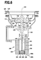
- the drainage opening 110 of the main basin 104 is arranged on the bottom 126 of a drain opening recess 112, which protrudes downwardly from the bottom 114 of a closure element receiving recess 116.
- the closure member receiving recess 116 projects downwardly from the bottom 118 of the main basin 104.
- the outflow opening 110 can be closed by means of a closure element 120, which is formed substantially rotationally symmetrical about a vertical closure element axis 122.
- the closure member 120 includes a substantially cylindrical closure member body 124 which penetrates a central through-hole in the bottom 126 of the drainage aperture depression 112.
- the central through-hole at the bottom 126 of the drain opening recess 112 is surrounded by a plurality of further through-holes 128, through which water can exit downwardly from the drain hole recess 112 into an angled drain pipe section 130.
- the upper portion of the closure element main body 124 is surrounded by a strainer element 132 like a collar.
- the Siebkorbelement 132 is provided with circumferentially equidistantly distributed Sieb trimgangsö réelleen 134.
- a sealing collar 136 which likewise surrounds the closure element base body 124 in a collar-like manner, is arranged, from the outer edge of which an elastic sealing lip 138 which surrounds the sealing collar 136 in an annular manner protrudes.
- this sealing lip 138 is in the closed position of the closure member 120 at the inner edge of the bottom 114 of the closure member receiving recess 116 and thus prevents in the closed position that water from the closure member receiving recess 116 enters the drain opening recess 112.
- the closure member 120, the closure member receiving recess 116, and the drain opening recess 112 together form a drain valve assembly 139.
- the closure element main body 124 is displaceably guided in a hollow cylindrical retaining sleeve 140 along the closure element axis 122.
- closure element main body 124 engages an upper end of a piston rod 144 of an armature 146, which along with a the central axis of the closure element 120 coaxial coil axis 149 slidably held in a central cavity 152 of a magnetic coil 154 of a designated as a whole by 148 electromagnet.
- disk-shaped collar 156 On the armature 146 a projecting in the radial direction, disk-shaped collar 156 is provided on the underside of the upper end of a compression coil spring 158 is applied, which is supported at its lower end to a lower end wall 160 of a substantially hollow cylindrical housing 164 of the electromagnet 148 ,
- This compression coil spring 158 acts as a return element 162, which biases the armature 146 into its upper end position and thus the closure element 120 into its open position (not shown), in which the closure element 120 releases the outflow opening 110.
- an elastically deformable buffer member 166 is arranged, which serves to dampen the impact of the armature 146 on the end wall 160 at the end of the closing operation of the closure member 120.
- the buffer element 166 may for example be formed of a rubber material, of a silicone material and / or of a foam material.
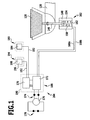
- the solenoid 154 of the solenoid 148 is connected via two power lines 168a, 168b to a controller 188 (see FIG Fig. 1 ), by means of which the voltage applied to the solenoid electrical voltage is controllable.
- the magnetic coil 154 of the electromagnet 148 is acted upon by the control device 188 with an electrical voltage, the magnetic field generated by the current flowing magnetic coil 154 pulls the armature 146 against the restoring force of the compression coil spring 158 down, so that with the upper end of the Ankers 146 connected closure element 120 in the in Fig. 6 shown closed position is moved, in which the closure element 120 closes the drain opening 110.
- the buffer element 166 could also be arranged on the inside of the lower end wall 160 instead of at the lower end of the armature 146.
- the control device 188 comprises a programmable microcontroller 170 and a voltage regulator 172, both of which are arranged in a housing 190 of the control device 188.
- the voltage regulator 172 is connected via a connecting cable 174 with a power supply 176, which in turn is connected to a socket 178 of the public power grid.
- the power supply 176 transforms the voltage of the public power grid down to a safety extra-low voltage, which is provided to the voltage regulator 172.
- the voltage regulator 172 supplies the microcontroller 170 and the electromagnet 148 with the required operating voltage.
- the microcontroller 170 receives signals from an actuator 194 which is connected to the microcontroller 170 via a signal line 192.
- the microcontroller 170 receives signals from a level sensor 180, which is connected to the microcontroller 170 via a signal line 182.
- the actuating device 194 comprises an actuating element 196, which is arranged, for example, on the underside of the battery bank 107.
- the actuating element 196 is designed in particular as a "touch-control" sensor and comprises a sensor 198, which may be designed, for example, as a capacitive sensor or as a piezoelectric sensor.
- the sensor 198 may be inserted into a matching recess on the underside of the sink 100 or into a through hole provided on the sink 100.
- a capacitive sensor 198 For use on a sink 100 of an electrically non-conductive material, in particular of a plastic material, of a composite material or of a natural stone material, in particular a capacitive sensor 198 is suitable.
- a capacitive sensor makes a capacitance change, which arises because a user the sink 100 inserts a body part, for example a finger, into the detection area of the sensor 198.
- piezoelectric sensor 198 responsive to the pressure generated upon contact of the top of the sink 100 in the detection area of the sensor 198 with a body part such as a user's finger.
- Such a piezoelectric sensor can also be used in the case of a sink 100 made of a non-electrically conductive material.
- the microcontroller 170 receives the control device 188 via the signal line 192 in response of the sensor 198, a signal, depending on which the microcontroller 170 controls the voltage regulator 172.
- the level sensor 180 comprises a sensor element 184 designed as a capacitive sensor, for example, which is mounted on the basin 104 of the sink 100 and serves as a water detector which generates an electrical signal when the capacitance changes as the water level rises to near the sensor element 184 which is forwarded to the microcontroller 170 of the controller 188.
- a sensor element 184 designed as a capacitive sensor, for example, which is mounted on the basin 104 of the sink 100 and serves as a water detector which generates an electrical signal when the capacitance changes as the water level rises to near the sensor element 184 which is forwarded to the microcontroller 170 of the controller 188.
- the microcontroller 170 of the control device 188 controls the voltage regulator 172 so that the closure element 120 by switching off the electromagnet 148 is moved to the open position.
- the sensor element 184 can in particular be mounted instead of the conventional overflow valve at the appropriate height.
- the electromagnetic drive device 202, the control device 188, the actuating device 194 and the level sensor 180 together form a movement device 204 for moving the closure element 120 of the drain valve arrangement 139.
- the microcontroller 170 of the controller 188 receives an actuation signal from the actuator 196, which is recognized as a regular actuation signal due to the conditions defined in the control program of the microcontroller 170, the microcontroller 170 controls the voltage regulator 172 so that the connected to the Solenoid coil 154 applied voltage at time t 1 is suddenly increased from zero to the maximum voltage UM, as shown in Fig. 7 is shown.
- the magnetic coil 154 generates the maximum magnetic force with which the armature 146 is drawn into the cavity 152 in the interior of the magnetic coil 154.
- This magnetic attraction force is significantly greater than the restoring force of the compression coil spring 158, so that the armature 146 after is pulled down until it abuts with the buffer member 166 on the lower end wall 160 of the housing 164 of the electromagnet 148.
- the voltage applied to the solenoid 154 voltage is reduced at a time t 2 to a holding voltage U H.
- the holding voltage U H is chosen so that the magnetic force generated upon application of this holding voltage to the magnetic coil 154 is just greater than the restoring force of the compression coil spring 158 in the closed position of the closure element 120th
- the microcontroller 170 of the control device 188 controls a movement of the closure element 120 of FIG the in Fig. 6 illustrated closed position in the open position by the voltage regulator 172 is controlled so that the voltage applied to the solenoid 154 voltage at a time t 3 is suddenly dropped to zero.
- FIG. 2 shows the time profile of the voltage applied to the magnetic coil 154 in an alternative embodiment of the movement device 204, in which the voltage applied to the magnetic coil 154 is not abruptly changed at the beginning of the closing process or at the beginning of the opening process, but modulated so that An excessive acceleration of the armature 146 during the closing operation and during the opening operation is avoided and thus the speed of movement of the closure member 120 is reduced when approaching the closed position and the approach to the open position.
- This alternative time profile of the voltage applied to the magnetic coil 154 electrical voltage is obtained by a corresponding programming of the microcontroller 170 of the control device 188, which in turn controls the voltage regulator 172 accordingly.
- the microcontroller 170 of the controller 188 When the closure member 120 is in the open position and the microcontroller 170 of the controller 188 is from the actuator 196 receives an actuation signal which is recognized as a regular actuation signal due to the conditions defined in the control program of the microcontroller 170, the microcontroller 170 controls a movement of the closure element 102 from the open position to the closed position by actuating the voltage regulator 172 in such a way that the voltage applied to the magnetic coil 154 during the closing operation between two times t 1 and t 2 increases stepwise, with several successive stages, from zero to the maximum closing voltage UM.
- this voltage increase can be stepped, ie with a large number of respectively approximately equal rise stages, as in FIG Fig. 8 shown.
- the voltage increase during the closing process may also be continuous, i. without jumps, done.
- the armature 146 in its lower end position does not hit so hard against the stop on the lower end wall 160 of the housing 164 of the electromagnet 148, so that no disturbing impact noise is generated.
- the closure member 120 along with the downward movement of the armature 146 from the open position to the in Fig. 6 shown closed position moves.
- the voltage applied to the magnetic coil 154 is reduced from the maximum closing voltage UM at a time t 3 to the smaller holding voltage U H.
- the microcontroller 170 of the control device 188 controls a movement of the closure element 120 from the closed position to the open position, by controlling the voltage regulator 172 such that the voltage applied to the magnetic coil 154 during the opening operation of the closure element 120 between a time t 4 and a time t 5 stepwise, in several stages, of the holding voltage U H drops to zero.
- the magnetic attraction force acting on the armature 146 also decreases gradually, so that the armature 146 from the restoring force of the compression coil spring 158 only slowly, without strong acceleration, out of the solenoid 154 out is moved.
- the closure element 120 moves from the closed position to the open position, so that overshoot of the closure element beyond the desired open position is prevented upwards.
- the stop of the armature 146 is damped against a stop at the upper end of the housing 164 of the electromagnet 148, so that in particular no disturbing impact noise is generated.
- this second embodiment of a movement device 204 with respect to structure and function is the same as the first embodiment, to the above description of which reference is made.
- FIG. 9 The illustrated third embodiment of a movement device 204 for moving the closure element 120 differs from the above-described embodiments in that the armature 146 does not act directly on the closure element main body 124, but that a free end of the armature 146 arranged outside the magnetic coil 154 has a free end first lever arm 210 is connected to a reversing lever 208 rotatably supported about a horizontal axis of rotation 206, which has a further (not shown) lever arm which is offset from the first lever arm 210 by approximately 90 ° and acts on the lower end of the closure element main body 124 that the closure member 120 is moved upwardly to the open position when the armature 146 leaves the solenoid 154 (in FIG Fig. 9 to the left), and that the shutter 120 is moved down to the closed position when the armature 146 engages the solenoid 154 (in FIG Fig. 9 to the right).
- an electromagnetic drive device 202 for driving the movement of the closure element 120 can also be used if there is little or no space available under the drain valve arrangement 139 for the arrangement of the electromagnet 148.
- the direction of movement 212 of the armature 146 is tilted by approximately 90 ° with respect to the direction of movement 214 of the closure element 120.
- Fig. 9 illustrated third embodiment of a moving means 204 in structure and function with the two first embodiments, which in the Fig. 1 to 8 , to the above description of which reference is made.
Landscapes
- Engineering & Computer Science (AREA)
- Mechanical Engineering (AREA)
- Environmental & Geological Engineering (AREA)
- Health & Medical Sciences (AREA)
- Life Sciences & Earth Sciences (AREA)
- Hydrology & Water Resources (AREA)
- Public Health (AREA)
- Water Supply & Treatment (AREA)
- Magnetically Actuated Valves (AREA)
- Power-Operated Mechanisms For Wings (AREA)
Applications Claiming Priority (1)
| Application Number | Priority Date | Filing Date | Title |
|---|---|---|---|
| DE200710008376 DE102007008376A1 (de) | 2007-02-21 | 2007-02-21 | Bewegungseinrichtung zum Bewegen eines Verschlusselements zum Verschließen einer Abflussöffnung |
Publications (2)
| Publication Number | Publication Date |
|---|---|
| EP1961874A2 true EP1961874A2 (fr) | 2008-08-27 |
| EP1961874A3 EP1961874A3 (fr) | 2012-10-31 |
Family
ID=39400459
Family Applications (1)
| Application Number | Title | Priority Date | Filing Date |
|---|---|---|---|
| EP08002235A Withdrawn EP1961874A3 (fr) | 2007-02-21 | 2008-02-07 | Dispositif de déplacement destiné au déplacement d'un élément de verrouillage pour le verrouillage d'une ouverture d'écoulement |
Country Status (2)
| Country | Link |
|---|---|
| EP (1) | EP1961874A3 (fr) |
| DE (1) | DE102007008376A1 (fr) |
Cited By (5)
| Publication number | Priority date | Publication date | Assignee | Title |
|---|---|---|---|---|
| EP2845957A1 (fr) | 2013-09-09 | 2015-03-11 | Intra Holding AS | Bouche d'égout pour un evier |
| CN104532925A (zh) * | 2014-12-28 | 2015-04-22 | 饶建明 | 一种水槽排水集排双控阀 |
| DE202016103243U1 (de) | 2016-06-20 | 2016-07-06 | Suter Inox Ag | Wannen- oder beckenartiges Behältnis, insbesondere Sanitärwanne, Sanitärbecken oder Spülenbecken |
| CN110219355A (zh) * | 2019-07-24 | 2019-09-10 | 北京康之维科技有限公司 | 小便器磁悬浮冲排封闭隔臭方法及装置 |
| CN110258732A (zh) * | 2019-07-24 | 2019-09-20 | 北京康之维科技有限公司 | 盥洗盆磁悬浮排放封闭隔臭方法及装置 |
Families Citing this family (3)
| Publication number | Priority date | Publication date | Assignee | Title |
|---|---|---|---|---|
| DE102023130873B3 (de) | 2023-11-08 | 2025-01-30 | Freilauf GmbH & Co. KG | Ablaufventil |
| DE102024111034A1 (de) * | 2024-04-19 | 2025-10-23 | Manus Leyendecker | Ablaufventil für einen Behälter |
| EP4570998A1 (fr) | 2023-11-08 | 2025-06-18 | Freilauf GmbH & Co. KG | Soupape de vidange pour une récipient |
Citations (1)
| Publication number | Priority date | Publication date | Assignee | Title |
|---|---|---|---|---|
| DE4241023A1 (de) | 1992-12-05 | 1994-06-09 | Heinrich Demandt | Vorrichtung zur Verhinderung oder Verminderung der durch Waschbecken, Spülbecken, Badewannen o. dgl. verursachten Keime |
Family Cites Families (1)
| Publication number | Priority date | Publication date | Assignee | Title |
|---|---|---|---|---|
| US5363519A (en) * | 1992-12-23 | 1994-11-15 | Kohler Co. | Drain valve assembly |
-
2007
- 2007-02-21 DE DE200710008376 patent/DE102007008376A1/de not_active Withdrawn
-
2008
- 2008-02-07 EP EP08002235A patent/EP1961874A3/fr not_active Withdrawn
Patent Citations (1)
| Publication number | Priority date | Publication date | Assignee | Title |
|---|---|---|---|---|
| DE4241023A1 (de) | 1992-12-05 | 1994-06-09 | Heinrich Demandt | Vorrichtung zur Verhinderung oder Verminderung der durch Waschbecken, Spülbecken, Badewannen o. dgl. verursachten Keime |
Cited By (9)
| Publication number | Priority date | Publication date | Assignee | Title |
|---|---|---|---|---|
| EP2845957A1 (fr) | 2013-09-09 | 2015-03-11 | Intra Holding AS | Bouche d'égout pour un evier |
| NO337297B1 (no) * | 2013-09-09 | 2016-03-07 | Intra Holding As | Anordning ved utløp i oppvaskkum |
| CN104532925A (zh) * | 2014-12-28 | 2015-04-22 | 饶建明 | 一种水槽排水集排双控阀 |
| CN104532925B (zh) * | 2014-12-28 | 2016-02-03 | 衢州市依科达节能技术有限公司 | 一种水槽排水集排双控阀 |
| DE202016103243U1 (de) | 2016-06-20 | 2016-07-06 | Suter Inox Ag | Wannen- oder beckenartiges Behältnis, insbesondere Sanitärwanne, Sanitärbecken oder Spülenbecken |
| CN110219355A (zh) * | 2019-07-24 | 2019-09-10 | 北京康之维科技有限公司 | 小便器磁悬浮冲排封闭隔臭方法及装置 |
| CN110258732A (zh) * | 2019-07-24 | 2019-09-20 | 北京康之维科技有限公司 | 盥洗盆磁悬浮排放封闭隔臭方法及装置 |
| CN110258732B (zh) * | 2019-07-24 | 2024-09-13 | 北京康之维科技有限公司 | 盥洗盆磁悬浮排放封闭隔臭方法及装置 |
| CN110219355B (zh) * | 2019-07-24 | 2024-11-26 | 北京康之维科技有限公司 | 小便器磁悬浮冲排封闭隔臭方法及装置 |
Also Published As
| Publication number | Publication date |
|---|---|
| DE102007008376A1 (de) | 2008-08-28 |
| EP1961874A3 (fr) | 2012-10-31 |
Similar Documents
| Publication | Publication Date | Title |
|---|---|---|
| EP1961874A2 (fr) | Dispositif de déplacement destiné au déplacement d'un élément de verrouillage pour le verrouillage d'une ouverture d'écoulement | |
| DE69931196T2 (de) | Magnetisch betätigter schwimmschalter | |
| DE69820286T2 (de) | Magnetventil mit haltevorrichtung | |
| EP2304144B1 (fr) | Butoir de porte escamotable | |
| EP3211280B1 (fr) | Vanne à gaz et son procédé de commande | |
| DE102014225756B4 (de) | Vorrichtung zur elektrischen Auslösung eines Spülvorgangs in einem sanitären Spülkasten | |
| DE19633178A1 (de) | Steuerung für ein mit Unterdruck betätigbares Absaug- und/oder Wasserventil | |
| EP1961872A2 (fr) | Dispositif de déplacement destiné au déplacement d'un élément de verrouillage pour le verrouillage d'une ouverture d'écoulement | |
| EP3625809B1 (fr) | Procédé pour la commutation d'une électrovalve | |
| EP1964988B1 (fr) | Dispositif de chasse d'eau électromécanique | |
| EP2497854B1 (fr) | Agencement de verrouillage d'une porte d'un appareil ménager ainsi qu'appareil ménager | |
| EP2678482B1 (fr) | Installation d'évacuation, soupape et procédé de drainage des eaux grises pour un avion de ligne | |
| EP3121495B2 (fr) | Vanne de commande electromagnetique | |
| DE60108898T2 (de) | Elektromagnetisches zweiwegeventil | |
| DE1959591A1 (de) | Bimetall-Temperaturregler | |
| DE102006048913A1 (de) | Schwingungsdämpfer mit verstellbarer Dämpfkraft | |
| EP4499930A1 (fr) | Réservoir, en particulier réservoir encastré, destiné à des toilettes ou à des urinoirs | |
| DE10327209B3 (de) | Schaltvorrichtung, insbesondere zum Betätigen von Ventilen | |
| DE2657197A1 (de) | Elektromagnetische ventileinrichtung | |
| EP0529237B1 (fr) | Dispositif de chasse d'eau | |
| DE19811920C2 (de) | Regenwasser-Versorgungsvorrichtung | |
| EP1672130B1 (fr) | Soupape d'évacuation d'un réservoir de chasse | |
| EP3138970B1 (fr) | Dispositif de rinçage | |
| EP1961873A1 (fr) | Dispositif de déplacement destiné au déplacement d'un élément de verrouillage pour le verrouillage d'une ouverture d'écoulement | |
| DE3640216A1 (de) | Klosettspuelkasten |
Legal Events
| Date | Code | Title | Description |
|---|---|---|---|
| PUAI | Public reference made under article 153(3) epc to a published international application that has entered the european phase |
Free format text: ORIGINAL CODE: 0009012 |
|
| AK | Designated contracting states |
Kind code of ref document: A2 Designated state(s): AT BE BG CH CY CZ DE DK EE ES FI FR GB GR HR HU IE IS IT LI LT LU LV MC MT NL NO PL PT RO SE SI SK TR |
|
| AX | Request for extension of the european patent |
Extension state: AL BA MK RS |
|
| PUAL | Search report despatched |
Free format text: ORIGINAL CODE: 0009013 |
|
| AK | Designated contracting states |
Kind code of ref document: A3 Designated state(s): AT BE BG CH CY CZ DE DK EE ES FI FR GB GR HR HU IE IS IT LI LT LU LV MC MT NL NO PL PT RO SE SI SK TR |
|
| AX | Request for extension of the european patent |
Extension state: AL BA MK RS |
|
| RIC1 | Information provided on ipc code assigned before grant |
Ipc: E03C 1/23 20060101AFI20120927BHEP |
|
| AKY | No designation fees paid | ||
| REG | Reference to a national code |
Ref country code: DE Ref legal event code: R108 |
|
| REG | Reference to a national code |
Ref country code: DE Ref legal event code: R108 Effective date: 20130703 |
|
| STAA | Information on the status of an ep patent application or granted ep patent |
Free format text: STATUS: THE APPLICATION IS DEEMED TO BE WITHDRAWN |
|
| 18D | Application deemed to be withdrawn |
Effective date: 20130503 |