EP1961891B1 - Système comportant un cadre et un cache détachable pour une ouverture dans un mur ou un plafond - Google Patents
Système comportant un cadre et un cache détachable pour une ouverture dans un mur ou un plafond Download PDFInfo
- Publication number
- EP1961891B1 EP1961891B1 EP07102884A EP07102884A EP1961891B1 EP 1961891 B1 EP1961891 B1 EP 1961891B1 EP 07102884 A EP07102884 A EP 07102884A EP 07102884 A EP07102884 A EP 07102884A EP 1961891 B1 EP1961891 B1 EP 1961891B1
- Authority
- EP
- European Patent Office
- Prior art keywords
- cover
- frame
- carrying frame
- gripping
- opening
- Prior art date
- Legal status (The legal status is an assumption and is not a legal conclusion. Google has not performed a legal analysis and makes no representation as to the accuracy of the status listed.)
- Active
Links
Images




Classifications
-
- E—FIXED CONSTRUCTIONS
- E04—BUILDING
- E04F—FINISHING WORK ON BUILDINGS, e.g. STAIRS, FLOORS
- E04F19/00—Other details of constructional parts for finishing work on buildings
- E04F19/08—Built-in cupboards; Masks of niches; Covers of holes enabling access to installations
- E04F19/083—Covers with fixing means providing for snap locking
-
- E—FIXED CONSTRUCTIONS
- E05—LOCKS; KEYS; WINDOW OR DOOR FITTINGS; SAFES
- E05B—LOCKS; ACCESSORIES THEREFOR; HANDCUFFS
- E05B5/00—Handles completely let into the surface of the wing
-
- E—FIXED CONSTRUCTIONS
- E05—LOCKS; KEYS; WINDOW OR DOOR FITTINGS; SAFES
- E05C—BOLTS OR FASTENING DEVICES FOR WINGS, SPECIALLY FOR DOORS OR WINDOWS
- E05C3/00—Fastening devices with bolts moving pivotally or rotatively
- E05C3/02—Fastening devices with bolts moving pivotally or rotatively without latching action
- E05C3/04—Fastening devices with bolts moving pivotally or rotatively without latching action with operating handle or equivalent member rigid with the bolt
- E05C3/047—Fastening devices with bolts moving pivotally or rotatively without latching action with operating handle or equivalent member rigid with the bolt rotating about an axis parallel to the surface on which the fastener is mounted
- E05C3/048—Fastening devices with bolts moving pivotally or rotatively without latching action with operating handle or equivalent member rigid with the bolt rotating about an axis parallel to the surface on which the fastener is mounted parallel to the wing edge
Definitions
- the present invention relates to a system comprising a carrying frame and a cover for camouflaging of a technical gap, so as for example of a gap for access to an electro meter, water meters, water closures, etc., made in a wall or a ceiling of a building.
- Such a carrying frame with a cover is disclosed for example in the document DE 92 10 905 U1 .
- the covering plate is fixed to the frame demountably by means of screws. Screwing of the covering plate to the frame during assembly or unscrewing of the screws during repairs and inspections is lengthy. The carrying frame or the covering plate can be damaged if the screws are tightened up too much and a screw can be lost.
- the document EP 779 397 B1 discloses a covering arrangement for a gap, particularly for an inspection gap, which arrangement comprises a frame situated in a gap and a covering plate, which covering plate covers the frame and is joined with the frame demountably.
- the covering plate is provided with a controlling element.
- the covering plate is also provided with a border part, which border part protrudes from its face surface backwards, in the direction to the frame, and forms a border of the frame.
- the frame comprises at least one latch, which latch is mounted flexibly by means of a spring, and which is fixed in the mounting part so that it cannot be lost.
- the plate is provided with a snap-in element, and in the area of the opposite side, it is provided with catching elements, to which catching elements the corresponding recesses are formed in the frame.
- the snap-in element is engaged with the corresponding latch and the catching elements are engaged with the corresponding recesses.
- a disadvantage of this embodiment is on the one hand that to remove the covering plate it is necessary to use a special tool, which tool is inserted into a tool recess of the unblocking element and by which the return spring of the latch is pushed, and on the other hand that the covering plate protrudes above the surrounding surface substantially.
- designs of the carrying frame are known, in which the carrying frame has the L-letter form in its cross section, as well as designs of the covering plate, in which the covering plate is placed in the opening of the carrying frame and in which in the area of one of its sides the covering plate is provided with put-on grips on its internal surface, which put-on grips can grip behind the protrusions of the carrying frame or in the corresponding openings in the carrying frame.
- the covering plate is provided with one gripping element on the inner side, which gripping element is adjustable by turning of a controlling element passing through the cover plate and is grippable behind the protrusion of the carrying frame or in an opening in the carrying frame.
- An advantage of this embodiment is that it protrudes only minimally above the surrounding surface, but to remove the covering plate and to put it again to its place, it is necessary to use a tool again, in this case a screwdriver, which screwdriver is inserted into the recess in the controlling element.
- a tool again in this case a screwdriver, which screwdriver is inserted into the recess in the controlling element.
- Another disadvantage can be seen in an uneven adhering and centring of the cover plate in the carrying frame because of the necessary production tolerances of their individual parts.
- the device is comprised of a cover sunk in an opening in the wall by means of a composed frame profile.
- the frame is composed of two rectangular elements.
- the outer one of the elements has a circumferential part, which part fits into the opening in the wall and is directed to the outer surface of the wall, and an outward flange, which is situated between the wall and the wall framework, being directed towards the outside of the wall opening and fixed to the framework.
- the inner one of the elements has a circumferential part, which part is fixed to the inner surface of the circumferential part of the first element in the area of the opening in the wall, and simultaneously, it is prolonged into the opening of the wall framework, which opening is continuation of the opening in the wall, so that the opening secures embedding of the circumferential part of the first element.
- the inner element has an inner flange, which flange is placed distantly with regard to the frame of the wall framework and is directed into the wall opening. On the inner flange there is a demountably embedded closure panel, embedded in the wall, so that its upper surface area is situated flush with the plane of the outer wall surface area.
- the closure panel is entirely concealed by paper or by other wall lining, where the play in the connection between the panel and the circumferential part 9 of the first element allows extraction of the panel from the frame profile.
- the closure panel having the shape of a planar plate is secured in the frame of the wall opening by inner catches snapped against cut outs in the inner flange, which cut outs are formed with spaces with regard to the flange to allow pressing of the inner catches of the panel inwards and their snapping against the cut outs.
- the closure panel is releasable by prying the panel out of the frame of the wall opening.
- the frame consists of an outer flange, which flange is parallel with a wall with an opening and is placed of the surface area of the wall around the opening, and of an arm substantially perpendicular to the flange and extending in the direction outwards from the wall.
- the arm is provided with inner flange, which flange is parallel to the outer flange of the frame and includes a projection in the middle of one of its sides, which projection is provided with a threaded opening for a screw of the cover.
- An opening for the cover is formed in the arm above the flange, which cover is placed on the flange.
- the system wherein the carrying frame is also characterized in that the assembly openings are oval and are arranged along the whole circumferential length both of the arm part of the outer frame and of its arm, which is parallel with the axis of the technical gap on the outer side in the area above shorter vertical part of the carrying frame profile.
- the outer surface of the controlling element and the outer surface of the flap fit with the outer surface of the cover and the through opening in the cover has the form of an elongated rectangle.
- the cover according to the present invention it is substantial that it is provided with two gripping elements, with controlling elements arranged in two through-openings, of which each is adjacent to one of the two neighbouring cover corners, wherein the through openings are arranged either one after the other and are parallel with the axis passing through the put-on grips, or they are arranged next to each other and perpendicularly to the axis passing through the put-on grips.
- the flap is provided with protrusions or recesses making the surface coarse
- the gripping elements are provided with an adjustable gripping surface on the side determined for securing behind the gripping part of the carrying frame profile, and that the put-on grips are arranged adjustably perpendicularly to the adjacent outer cover border.
- the wedge-shaped protrusions are formed on the inner reinforcing ribbing of the cover and that there are six wedge-shaped protrusions and that they are arranged two next to each other on three sides of the cover.
- An advantage of the system of the carrying frame and the cover according to the present invention is particularly that it is not necessary to use any tool during putting of the cover into the carrying frame and in taking the cover from the carrying frame, regular adhering and perfect centring of the cover in the carrying frame, integrity of the outside surface of the cover and merging of the cover surface with the surface surrounding the technical gap.
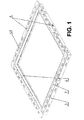
- a carrying frame 1 for fixing of a cover 2 of a technical gap so as for example of a gap for access to an electro meter, water meters, water closures, etc., made in a wall or a ceiling of a building, according to present invention, has in its cross section the form of a combined open profile, the outer frame 3 of which is on the outer side of the frame 1 adjacent to the cover 2 provided with a to the axis of the technical gap laterally situated arm part 5 oriented in the direction away from one arm of the inner frame 4 , which is parallel with the axis of the technical gap.
- the inner frame 4 on its side turned away from the arm part 5 , passes by its other arm, which arm is perpendicular to the axis of the technical gap, and adapted on the inner side of the carrying frame 1 , which is placed distantly to the plane of the cover 2 and forming gripping part 16 into the outer frame 3 .
- Both the arm part 5 and the outer frame 3 of the profile of the carrying frame 1 are provided with assembly openings 6 , in this case with oval ones.
- the cover 2 has the form of a plate and on its inner side, at one of its outer circumferential edge, it is provided with two put-on grips 8 (see Fig. 3 and Fig. 6 ) and at the opposite outer circumferential edge, it is provided with two adjustable gripping elements 9 , each of which is provided with a control element 10, for fixing of the cover 2 in the carrying frame 1 .
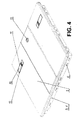
- Each gripping element 9 has, together with the controlling element 10 , the form resembling the letter Z (see Fig. 2 ), and is pivotably mounted in the through opening 11 in the cover 2 so that in the rest state, in the self-locking securing of the gripping element 9 behind the gripping part 16 of the carrying frame 1 profile (see Fig. 5 ), the outer surface of the controlling element 10 is parallel with the outer surface of the cover 2 (see Fig. 4 ), in a preferable embodiment so that it fits with it.
- a flap 12 is mounted pivotably springingly. Its mounting is carried out so that its outer surface is parallel with the outer surface of the cover 2 in the rest state of the flap 12 (see Fig. 4 ), in a preferable embodiment so that it fits with it.
- the wedge-shaped protrusions 14 are arranged (see Fig. 3 ,) entering into the space between the shorter vertical part and the low end of the longer vertical part of the carrying frame 1 profile.
- the wedge-shaped protrusions 14 are preferably formed on the inner reinforcing ribbing 15 of the cover 2 and they are arranged two next to each other on all sides of the cover 2 (see Fig. 3 ), with the exception of the side at which the put-on grips 8 are provided.
- the through openings 11 in the cover 2 have in this case the form of an elongated rectangle.
- other suitable form can also be used, for example the oval form.
- the through openings 11 are adjacent each to one of the two neighbouring corners of the cover 2 .
- the through-openings 11 are arranged one after the other and are parallel with the axis passing through the put-on grips 8 . But also they can be arranged next to each other and perpendicularly to the axis passing through the put-on grips.
- each flap 12 is provided with coarse making protrusions or recesses on its outer surface.
- Fig. 5 It is also preferable (see Fig. 5 ) to provide the gripping elements 9 on the side determined for fastening behind the gripping part 16 of the carrying frame 1 profile with an adjustable gripping surface, in this particular case controlled by a screw with hollow head with hexagon socket, and to arrange the put-on grips 8 adjustably perpendicularly to the adjacent outer border of the cover 2 (see Fig. 3 and Fig. 6 ).
- the cover 2 (see Fig. 5 ) is provided with a lamella lock 13 , the latch of which is locked behind the gripping part 16 of the carrying frame 1 profile.
- the form and the size of the outer borders of the cover 2 correspond to the form and size of the outer borders of the arm part 5 of the carrying frame 1 profile.
- a carrying frame 1 is inserted into a technical gap so that its arm part 5 sits down by its inner surface, adjacent to the longer arm, which is parallel with the axis of the technical gap of the outer frame 3 of the profile of the carrying frame 1 , to the surface of a wall or a ceiling. Thereafter, the carrying frame 1 is fixed by wood screws, passing through the assembly openings 6 , in the longer arm and the arm part 5 of the outer frame 3 of the carrying frame 1 profile, or by another suitable known process, to a wall or a ceiling of a building.
- the flaps 12 are pushed at once, or one after the other, by a finger of a hand, in the direction to the inner surface of the cover 2 , whereby, the force of a spring, with which each flap 12 is provided, is overwhelmed for the purpose to return it to the starting resting position.
- the end of the controlling element 10 is caught simultaneously, and by exerting a traction force to the end of the controlling element 10 this controlling element 10 is pivoted to the position, in which it is arranged laterally to the outer surface of the cover 2 .
- the flap 12 returns to its starting resting position by action of the spring.
- both controlling elements 10 are pivoted to a position lateral to the outer surface of the cover 2 , it is possible to start assembly of the cover 2 into the carrying frame 1 .
- the cover 2 is now placed in front of the carrying frame 1 , and this into a position, in which the plane intersecting the cover 2 makes an acute angle with the wall surface or the ceiling surface, and in which the border of the cover 2 , to which the put-on grips 8 are adjacent, is parallel with one border of the carrying frame 1 and is situated next to it, in its close vicinity.
- the cover 2 is caught up by means of the put-on grips 8 behind the gripping part 16 in the adjacent border of the carrying frame 1 .
- the cover 2 is pressed to the carrying frame 1 , in which action the wedge-shaped protrusions 14 , arranged on the inner stiffening ribbing 15 of the cover 2 , are inserted into the space between the axially oriented arms of the frames 3 and 4 of the carrying frame 1 profile and the cover 2 is centred with regard to the carrying frame 1 , so that the borders of the cover 2 fit with the outer borders of the arm part 5 of the carrying frame 1 .
- the wedge-shaped protrusions 14 prevent any movement of the cover 2 along the carrying frame 1.
- the cover 2 is disassembled from the carrying frame 1 and before its new assembly into the carrying frame 1 the distance of the put-on grips 8 to the adjacent border of the cover 2 is decreased and/or their adjustable gripping surfaces are moved more out from the gripping elements 9 .
Landscapes
- Engineering & Computer Science (AREA)
- Architecture (AREA)
- Civil Engineering (AREA)
- Structural Engineering (AREA)
- Mechanical Engineering (AREA)
- Building Environments (AREA)
- Door And Window Frames Mounted To Openings (AREA)
- Residential Or Office Buildings (AREA)
- Specific Sealing Or Ventilating Devices For Doors And Windows (AREA)
Claims (15)
- Système comprennant un cadre-support (1) et une couvercle (2), où ledit cadre-support (1) est destiné à l'attachement de ladite couvercle au trou technique, tel que le trou d'accès au compteur d'électricité, aux compteurs ou obturateurs d'eau et analogues, formé dans une parois ou sur un plancher de la construction, ladite couvercle comprend un cadre (3) extérieur et un cadre (4) intériere qui sont liés l'un à l'autre, où ledit cadre (3) extérieur présente une partie (5) à branches s'étandant du cadre (3) extérieur perpendiculairemet à l'axe de trou technique, où ledit cadre (3) extérieur avec la partie (5) à branches sont munis des ouvetures de montage, où les deux cadres (3, 4) présent une section sensiblement d'une forme d'équerre, où la partie (5) à branches du cadre (3) extérieur est agencée sur le côté extérieur du cadre (1), la première branche du cadre (4) intérieur est parallère à l'axe du trou technique tandis que la deuxième branche est agencée sur la partie intérieure du cadre (1), caractérisé en ce que ladite deuxième branche est perpendiculaire à l'axe du trou technique, côté intérieur est distant du plan du couvercle et forme une partie (16) d'accrochage reliant ledit cadre (4) intérieur avec ledit cadre (3) extérieur, et l'espace entre les branches (3, 4) axialement orientées, qui forme une partie du système pour le centrage du couvercle (2) dans le cadre-support (1), est muni dans le pourtour dudit cadre-support (1) d'un système de renforts (7).
- Système selon la revendication 1, caractérisé en ce que les troux (6) de montage sont ovales.
- Système selon l'une des revendications 1 ou 2, caractérisé en ce que les troux (6) de montage sont agencés sur toute la longueur périphérique de la partie (5) à branches dudit cadre (3) extérieur et de sa branche, lequel cadre (3) extérieur étant paralèlle à l'axe du trou technique sur la partie extérieure dans la zone au-dessus du cadre (4) intérieur du profil dudit cadre-support (1).
- Système comprennant un cadre-support (1) et une couvercle (2), où ladite couvercle (2) se présente sous forme d'une plaque destinée à être poser sur le cadre-support (1) et munie sur sa face intérieure, près de son arête périphérique intérieure, de deux attaches (8) d'emmanchement, caractérisé en ce que au moins un élément (9) d'accrochage ajustable, destiné à l'attachement de ladite couvercle (2) audit cadre-support (1), auquel est joint un élément (10) de commande et dont la surface extérieure est ménagée dans la zóne de la surface extérieure de ladite couvercle (2), se trouve près de l'arête exérieure opposée, ledit element (9) d'accrochage avec ledit element (10) de commande présentent la section longitudinale en Z et il est logé de façon basculant, de sorte que la surface extérieure de ledit element (10) de commande soit, lors d'accrochage à serrage automatique de ledit élément (9) d'accrochage derrière la partie (16) d'accrochage du profil dudit cadre-support (1), paralèle à la surface extérieure de ladite couvercle (2), pour rendre facile la préhension dudit element (10) de commande, un clapet (12) est disposé d'une manière basculant et par montage à ressorts dans un trou (11) de passage de la couvercle (2) en opposé au logement basculant de l'élément (9) d'accrochage avec l'élément de commande (10), ledit clapet est disposé de telle façon que sa surface extérieure se trouve pendant son état de repos dans le même plan avec la surface extérieure de ladite couvercle (2), et sur la surface intérieure de ladite couvercle (2), en vue de centrage de la couvercle (2) sur le cadre-support (1), sont ménagées au moins deux saillies (14) en forme de coin, qui sont perpendiculaires l'une à l'autre, et s'étendent dans l'espace entre la partie (4) plus courte verticale et l'extrémité inférieure de la partie (3) plus lonque verticale du profil dudit cadre-support (1).
- Système selon la revendication 4, caractérisé en ce que la surface extérieure dudit élément (10) de commande et la surface extérieure du clapet (12) s'alignent avec la surface extérieure de ladite couvercle (2)
- Système selon la revendication 4, caractérisé en ce que le trou (11) de passage dans la couvercle (2) se présent sous forme de rectangle allongé.
- Système selon la revendication 4, caractérisé en ce qu'il comprend deux éléments (9) d'accrochage avec des éléments de commande (10) qui sont ménagés dans deux troux (11) de passage dont chacun est adjacent à l'un de deux coins de ladite couvercle (2).
- Système selon la revendication 7, caractérisé en ce que lesdits troux (11) de passage sont agencés côte à côte et parallelement à l'axe passant par lesdites attaches (8) d'emmanchement.
- Système selon la revendication 7, caractérisé en ce que lesdits troux (11) de passage sont agencés côte à côte et perpendiculairement à l'axe passant par lesdites attaches (8) d'emmanchement.
- Système selon l'une quelconque des revendications 4 à 9, caractérisé en ce que ledit clapet (12) est muni, sur sa surface extérieure, des saillies ou évidements rendant la surface rugueuse.
- Système selon l'une quelconque des revendications 4 à 10, caractérisé en ce que lesdits éléments (9) d'accrochage sont munis, sur le côté destiné à l'accrochage derrière la partie (16) d'accrochage du profil dudit cadre-support (1), de la surface d'accrochage ajustable.
- Système selon l'une quelconque des revendications 4 à 11, caractérisé en ce que les attaches (8) d'emmanchement sont agencées d'une manière ajustable et perpendiculaire au bord extérieure adjacent de ladite couvercle (2).
- Système selon l'une quelconque des revendications 4 à 12, caractérisé en ce que le verrou (13) lamelleux est agencé dans sa zóne centrale, entre lesdits troux (11) de passage.
- Système selon l'une quelconque des revendications 3 à 13, caractérisé en ce que les saillies (14) en forme de coin sont crées sur le nervurage (15) de renforcement de ladite couvercle (2).
- Système selon la revendication 14, caractérisé en ce qu'il comprend six saillies (14) en forme de coin qui sont agencées par deux et côte à côte sur trois côtés de ladite couvercle (2).
Priority Applications (3)
| Application Number | Priority Date | Filing Date | Title |
|---|---|---|---|
| PL07102884T PL1961891T3 (pl) | 2007-02-22 | 2007-02-22 | System zawierający ramę nośną i odłączaną pokrywę dla otworu w ścianie lub suficie |
| EP07102884A EP1961891B1 (fr) | 2007-02-22 | 2007-02-22 | Système comportant un cadre et un cache détachable pour une ouverture dans un mur ou un plafond |
| AT07102884T ATE528461T1 (de) | 2007-02-22 | 2007-02-22 | System mit einem rahmen und einer lösbaren abdeckung für eine wand- oder deckenöffnung |
Applications Claiming Priority (1)
| Application Number | Priority Date | Filing Date | Title |
|---|---|---|---|
| EP07102884A EP1961891B1 (fr) | 2007-02-22 | 2007-02-22 | Système comportant un cadre et un cache détachable pour une ouverture dans un mur ou un plafond |
Publications (2)
| Publication Number | Publication Date |
|---|---|
| EP1961891A1 EP1961891A1 (fr) | 2008-08-27 |
| EP1961891B1 true EP1961891B1 (fr) | 2011-10-12 |
Family
ID=38324134
Family Applications (1)
| Application Number | Title | Priority Date | Filing Date |
|---|---|---|---|
| EP07102884A Active EP1961891B1 (fr) | 2007-02-22 | 2007-02-22 | Système comportant un cadre et un cache détachable pour une ouverture dans un mur ou un plafond |
Country Status (3)
| Country | Link |
|---|---|
| EP (1) | EP1961891B1 (fr) |
| AT (1) | ATE528461T1 (fr) |
| PL (1) | PL1961891T3 (fr) |
Cited By (1)
| Publication number | Priority date | Publication date | Assignee | Title |
|---|---|---|---|---|
| DE102025123594B3 (de) | 2025-05-02 | 2026-05-13 | KAIRISH INNOTECH Private Ltd. | Abdeckplatte mit abnehmbarer abdeckung und verwendungen derselben |
Families Citing this family (9)
| Publication number | Priority date | Publication date | Assignee | Title |
|---|---|---|---|---|
| FR2937664B1 (fr) * | 2008-10-24 | 2010-12-03 | Cofim | Dispositif de verrouillage d'un ouvrant sur un cadre |
| ITBO20090050U1 (it) * | 2009-06-23 | 2010-12-24 | Eur Ex S R L | Sportello con telaio a sovrapporre, particolarmente idonei per la chiusura di vani a muro ispezionabili. |
| RU2412315C1 (ru) * | 2009-12-02 | 2011-02-20 | Общество с ограниченной ответственностью "ВС-ГРУПП" | Люк скрытых инженерных систем |
| EP2381050A1 (fr) * | 2010-04-23 | 2011-10-26 | Vincent Damour | Dispositif de verrouillage d'un ouvrant sur un cadre |
| JP6312413B2 (ja) * | 2013-12-10 | 2018-04-18 | 吉川化成株式会社 | 床下収納庫又は点検口用の蓋体 |
| CZ28579U1 (cs) | 2015-07-08 | 2015-08-31 | Romba Drywall Cz S.R.O. | Kryt revizního otvoru |
| GB2577667B (en) * | 2018-05-02 | 2023-03-01 | Linear Building Innovations Ltd | A hinged portal comprising a cover plate for concealing a lock |
| IT202300004008A1 (it) * | 2023-03-06 | 2024-09-06 | G P Innovazioni Srls | Botola perfezionata per pareti edilizie |
| US12492564B2 (en) * | 2023-04-24 | 2025-12-09 | Ascent Holdings, Llc | Access panel with mounting tabs |
Family Cites Families (5)
| Publication number | Priority date | Publication date | Assignee | Title |
|---|---|---|---|---|
| US1630906A (en) | 1927-02-23 | 1927-05-31 | Garry M Ketcham | Concealed inclosure |
| FR1474958A (fr) | 1966-02-11 | 1967-03-31 | Perfectionnement aux encadrements de porte de ramonage ou similaire | |
| DE8212069U1 (de) * | 1982-04-27 | 1982-07-08 | DIG Deutsche Innenbau GmbH, 4330 Mülheim | Bauelementensatz zum einbauen von zumindest einer auslenkbaren deckenplatte in eine abgehaengte decke |
| DE9210905U1 (de) | 1991-11-28 | 1992-10-08 | Geberit Ag, Jona, St.Gallen | Rahmen zum Auskleiden einer Wandaussparung |
| DE19547178C2 (de) | 1995-12-16 | 1998-08-20 | Friatec Ag | Abdeckanordnung |
-
2007
- 2007-02-22 EP EP07102884A patent/EP1961891B1/fr active Active
- 2007-02-22 AT AT07102884T patent/ATE528461T1/de not_active IP Right Cessation
- 2007-02-22 PL PL07102884T patent/PL1961891T3/pl unknown
Cited By (1)
| Publication number | Priority date | Publication date | Assignee | Title |
|---|---|---|---|---|
| DE102025123594B3 (de) | 2025-05-02 | 2026-05-13 | KAIRISH INNOTECH Private Ltd. | Abdeckplatte mit abnehmbarer abdeckung und verwendungen derselben |
Also Published As
| Publication number | Publication date |
|---|---|
| ATE528461T1 (de) | 2011-10-15 |
| EP1961891A1 (fr) | 2008-08-27 |
| PL1961891T3 (pl) | 2012-03-30 |
Similar Documents
| Publication | Publication Date | Title |
|---|---|---|
| EP1961891A1 (fr) | Cardre et cache détachable pour une ouverture dans un mur ou un plafond | |
| US4890418A (en) | Access panel assembly with door and multi-functional frame | |
| US5076626A (en) | Method and device for repairing or protecting a door and kit for doing same | |
| KR200460342Y1 (ko) | 창문형 에어컨 보조 창문 틀 | |
| US8813426B2 (en) | Duct access door | |
| US6722621B2 (en) | Electrical box assembly with removable protective cover | |
| USRE40600E1 (en) | Receptacle-mounted cover plate | |
| US8656645B1 (en) | Duct access door | |
| EP3059825A1 (fr) | Cadre et kit pour le montage de boites électriques ou automatisés à domicile | |
| US20060005470A1 (en) | Door threshold protective cover | |
| EP2710204B1 (fr) | Dispositif de montage, kit comprenant le dispositif de montage et élément de couverture, et procédé d'utilisation du kit | |
| US20040023005A1 (en) | Vent cover | |
| JPH03272307A (ja) | 板状物の取付構造 | |
| RU65542U1 (ru) | Несущая рама и крышка для маскировки технологического проема в стене или потолке здания | |
| JP4116374B2 (ja) | 配線用ボックス装置 | |
| JP2531245Y2 (ja) | 蝶番構造 | |
| CN213711556U (zh) | 一种防尘螺栓 | |
| JP6034594B2 (ja) | 戸当り | |
| JP2002174211A (ja) | 位置調整部材及びこれを用いた構造材 | |
| JPH0567788U (ja) | 多機能端部ブロック | |
| CN205153774U (zh) | 管形插销门挡组件 | |
| JPH0751532Y2 (ja) | カーテンウォールの無目取付構造 | |
| JP2003105905A (ja) | 家 具 | |
| KR101346948B1 (ko) | 천정판의 고정 구조 | |
| JP2000324651A (ja) | コンクリート壁埋込用電線ボックス |
Legal Events
| Date | Code | Title | Description |
|---|---|---|---|
| PUAI | Public reference made under article 153(3) epc to a published international application that has entered the european phase |
Free format text: ORIGINAL CODE: 0009012 |
|
| AK | Designated contracting states |
Kind code of ref document: A1 Designated state(s): AT BE BG CH CY CZ DE DK EE ES FI FR GB GR HU IE IS IT LI LT LU LV MC NL PL PT RO SE SI SK TR |
|
| AX | Request for extension of the european patent |
Extension state: AL BA HR MK RS |
|
| 17P | Request for examination filed |
Effective date: 20090219 |
|
| 17Q | First examination report despatched |
Effective date: 20090318 |
|
| AKX | Designation fees paid |
Designated state(s): AT BE BG CH CY CZ DE DK EE ES FI FR GB GR HU IE IS IT LI LT LU LV MC NL PL PT RO SE SI SK TR |
|
| AXX | Extension fees paid |
Extension state: RS Payment date: 20070222 Extension state: HR Payment date: 20070222 Extension state: BA Payment date: 20070222 Extension state: MK Payment date: 20070222 Extension state: AL Payment date: 20070222 |
|
| RTI1 | Title (correction) |
Free format text: A SYSTEM COMPRISING A CARRYING FRAME AND A DETACHABLE COVER FOR AN OPENING IN A WALL OR CEILING |
|
| GRAP | Despatch of communication of intention to grant a patent |
Free format text: ORIGINAL CODE: EPIDOSNIGR1 |
|
| RAX | Requested extension states of the european patent have changed |
Extension state: HR Payment date: 20070222 Extension state: BA Payment date: 20070222 Extension state: RS Payment date: 20070222 Extension state: MK Payment date: 20070222 |
|
| GRAS | Grant fee paid |
Free format text: ORIGINAL CODE: EPIDOSNIGR3 |
|
| GRAA | (expected) grant |
Free format text: ORIGINAL CODE: 0009210 |
|
| AK | Designated contracting states |
Kind code of ref document: B1 Designated state(s): AT BE BG CH CY CZ DE DK EE ES FI FR GB GR HU IE IS IT LI LT LU LV MC NL PL PT RO SE SI SK TR |
|
| AX | Request for extension of the european patent |
Extension state: BA HR MK RS |
|
| REG | Reference to a national code |
Ref country code: GB Ref legal event code: FG4D |
|
| REG | Reference to a national code |
Ref country code: CH Ref legal event code: EP |
|
| REG | Reference to a national code |
Ref country code: IE Ref legal event code: FG4D |
|
| REG | Reference to a national code |
Ref country code: DE Ref legal event code: R096 Ref document number: 602007017721 Country of ref document: DE Effective date: 20120105 Ref country code: RO Ref legal event code: EPE |
|
| REG | Reference to a national code |
Ref country code: NL Ref legal event code: VDEP Effective date: 20111012 |
|
| LTIE | Lt: invalidation of european patent or patent extension |
Effective date: 20111012 |
|
| REG | Reference to a national code |
Ref country code: PL Ref legal event code: T3 |
|
| REG | Reference to a national code |
Ref country code: AT Ref legal event code: MK05 Ref document number: 528461 Country of ref document: AT Kind code of ref document: T Effective date: 20111012 |
|
| PG25 | Lapsed in a contracting state [announced via postgrant information from national office to epo] |
Ref country code: LT Free format text: LAPSE BECAUSE OF FAILURE TO SUBMIT A TRANSLATION OF THE DESCRIPTION OR TO PAY THE FEE WITHIN THE PRESCRIBED TIME-LIMIT Effective date: 20111012 Ref country code: BE Free format text: LAPSE BECAUSE OF FAILURE TO SUBMIT A TRANSLATION OF THE DESCRIPTION OR TO PAY THE FEE WITHIN THE PRESCRIBED TIME-LIMIT Effective date: 20111012 Ref country code: IS Free format text: LAPSE BECAUSE OF FAILURE TO SUBMIT A TRANSLATION OF THE DESCRIPTION OR TO PAY THE FEE WITHIN THE PRESCRIBED TIME-LIMIT Effective date: 20120212 |
|
| PG25 | Lapsed in a contracting state [announced via postgrant information from national office to epo] |
Ref country code: SI Free format text: LAPSE BECAUSE OF FAILURE TO SUBMIT A TRANSLATION OF THE DESCRIPTION OR TO PAY THE FEE WITHIN THE PRESCRIBED TIME-LIMIT Effective date: 20111012 Ref country code: SE Free format text: LAPSE BECAUSE OF FAILURE TO SUBMIT A TRANSLATION OF THE DESCRIPTION OR TO PAY THE FEE WITHIN THE PRESCRIBED TIME-LIMIT Effective date: 20111012 Ref country code: GR Free format text: LAPSE BECAUSE OF FAILURE TO SUBMIT A TRANSLATION OF THE DESCRIPTION OR TO PAY THE FEE WITHIN THE PRESCRIBED TIME-LIMIT Effective date: 20120113 Ref country code: NL Free format text: LAPSE BECAUSE OF FAILURE TO SUBMIT A TRANSLATION OF THE DESCRIPTION OR TO PAY THE FEE WITHIN THE PRESCRIBED TIME-LIMIT Effective date: 20111012 Ref country code: PT Free format text: LAPSE BECAUSE OF FAILURE TO SUBMIT A TRANSLATION OF THE DESCRIPTION OR TO PAY THE FEE WITHIN THE PRESCRIBED TIME-LIMIT Effective date: 20120213 |
|
| PG25 | Lapsed in a contracting state [announced via postgrant information from national office to epo] |
Ref country code: CY Free format text: LAPSE BECAUSE OF FAILURE TO SUBMIT A TRANSLATION OF THE DESCRIPTION OR TO PAY THE FEE WITHIN THE PRESCRIBED TIME-LIMIT Effective date: 20111012 |
|
| PG25 | Lapsed in a contracting state [announced via postgrant information from national office to epo] |
Ref country code: SK Free format text: LAPSE BECAUSE OF FAILURE TO SUBMIT A TRANSLATION OF THE DESCRIPTION OR TO PAY THE FEE WITHIN THE PRESCRIBED TIME-LIMIT Effective date: 20111012 Ref country code: DK Free format text: LAPSE BECAUSE OF FAILURE TO SUBMIT A TRANSLATION OF THE DESCRIPTION OR TO PAY THE FEE WITHIN THE PRESCRIBED TIME-LIMIT Effective date: 20111012 Ref country code: EE Free format text: LAPSE BECAUSE OF FAILURE TO SUBMIT A TRANSLATION OF THE DESCRIPTION OR TO PAY THE FEE WITHIN THE PRESCRIBED TIME-LIMIT Effective date: 20111012 Ref country code: CZ Free format text: LAPSE BECAUSE OF FAILURE TO SUBMIT A TRANSLATION OF THE DESCRIPTION OR TO PAY THE FEE WITHIN THE PRESCRIBED TIME-LIMIT Effective date: 20111012 |
|
| PLBE | No opposition filed within time limit |
Free format text: ORIGINAL CODE: 0009261 |
|
| STAA | Information on the status of an ep patent application or granted ep patent |
Free format text: STATUS: NO OPPOSITION FILED WITHIN TIME LIMIT |
|
| PG25 | Lapsed in a contracting state [announced via postgrant information from national office to epo] |
Ref country code: IT Free format text: LAPSE BECAUSE OF FAILURE TO SUBMIT A TRANSLATION OF THE DESCRIPTION OR TO PAY THE FEE WITHIN THE PRESCRIBED TIME-LIMIT Effective date: 20111012 |
|
| REG | Reference to a national code |
Ref country code: DE Ref legal event code: R119 Ref document number: 602007017721 Country of ref document: DE |
|
| 26N | No opposition filed |
Effective date: 20120713 |
|
| PG25 | Lapsed in a contracting state [announced via postgrant information from national office to epo] |
Ref country code: MC Free format text: LAPSE BECAUSE OF NON-PAYMENT OF DUE FEES Effective date: 20120229 |
|
| REG | Reference to a national code |
Ref country code: CH Ref legal event code: PL |
|
| GBPC | Gb: european patent ceased through non-payment of renewal fee |
Effective date: 20120222 |
|
| PG25 | Lapsed in a contracting state [announced via postgrant information from national office to epo] |
Ref country code: CH Free format text: LAPSE BECAUSE OF NON-PAYMENT OF DUE FEES Effective date: 20120229 Ref country code: LI Free format text: LAPSE BECAUSE OF NON-PAYMENT OF DUE FEES Effective date: 20120229 |
|
| REG | Reference to a national code |
Ref country code: DE Ref legal event code: R097 Ref document number: 602007017721 Country of ref document: DE Effective date: 20120713 |
|
| REG | Reference to a national code |
Ref country code: IE Ref legal event code: MM4A |
|
| REG | Reference to a national code |
Ref country code: FR Ref legal event code: ST Effective date: 20121031 |
|
| REG | Reference to a national code |
Ref country code: HU Ref legal event code: AG4A Ref document number: E013969 Country of ref document: HU |
|
| REG | Reference to a national code |
Ref country code: DE Ref legal event code: R119 Ref document number: 602007017721 Country of ref document: DE Effective date: 20120901 |
|
| PG25 | Lapsed in a contracting state [announced via postgrant information from national office to epo] |
Ref country code: AT Free format text: LAPSE BECAUSE OF FAILURE TO SUBMIT A TRANSLATION OF THE DESCRIPTION OR TO PAY THE FEE WITHIN THE PRESCRIBED TIME-LIMIT Effective date: 20111012 Ref country code: FR Free format text: LAPSE BECAUSE OF NON-PAYMENT OF DUE FEES Effective date: 20120229 Ref country code: GB Free format text: LAPSE BECAUSE OF NON-PAYMENT OF DUE FEES Effective date: 20120222 Ref country code: IE Free format text: LAPSE BECAUSE OF NON-PAYMENT OF DUE FEES Effective date: 20120222 |
|
| PG25 | Lapsed in a contracting state [announced via postgrant information from national office to epo] |
Ref country code: ES Free format text: LAPSE BECAUSE OF FAILURE TO SUBMIT A TRANSLATION OF THE DESCRIPTION OR TO PAY THE FEE WITHIN THE PRESCRIBED TIME-LIMIT Effective date: 20120123 |
|
| PG25 | Lapsed in a contracting state [announced via postgrant information from national office to epo] |
Ref country code: FI Free format text: LAPSE BECAUSE OF FAILURE TO SUBMIT A TRANSLATION OF THE DESCRIPTION OR TO PAY THE FEE WITHIN THE PRESCRIBED TIME-LIMIT Effective date: 20111012 Ref country code: DE Free format text: LAPSE BECAUSE OF NON-PAYMENT OF DUE FEES Effective date: 20120901 |
|
| PG25 | Lapsed in a contracting state [announced via postgrant information from national office to epo] |
Ref country code: LU Free format text: LAPSE BECAUSE OF NON-PAYMENT OF DUE FEES Effective date: 20120222 |
|
| PGFP | Annual fee paid to national office [announced via postgrant information from national office to epo] |
Ref country code: RO Payment date: 20180220 Year of fee payment: 12 |
|
| PGFP | Annual fee paid to national office [announced via postgrant information from national office to epo] |
Ref country code: LV Payment date: 20180220 Year of fee payment: 12 Ref country code: TR Payment date: 20180321 Year of fee payment: 12 Ref country code: BG Payment date: 20180223 Year of fee payment: 12 Ref country code: HU Payment date: 20180216 Year of fee payment: 12 |
|
| PG25 | Lapsed in a contracting state [announced via postgrant information from national office to epo] |
Ref country code: RO Free format text: LAPSE BECAUSE OF NON-PAYMENT OF DUE FEES Effective date: 20190222 |
|
| PG25 | Lapsed in a contracting state [announced via postgrant information from national office to epo] |
Ref country code: LV Free format text: LAPSE BECAUSE OF NON-PAYMENT OF DUE FEES Effective date: 20190222 Ref country code: HU Free format text: LAPSE BECAUSE OF NON-PAYMENT OF DUE FEES Effective date: 20190223 Ref country code: BG Free format text: LAPSE BECAUSE OF NON-PAYMENT OF DUE FEES Effective date: 20190831 |
|
| PG25 | Lapsed in a contracting state [announced via postgrant information from national office to epo] |
Ref country code: TR Free format text: LAPSE BECAUSE OF NON-PAYMENT OF DUE FEES Effective date: 20190222 |
|
| PGFP | Annual fee paid to national office [announced via postgrant information from national office to epo] |
Ref country code: PL Payment date: 20260203 Year of fee payment: 20 |