EP1961931A1 - Abgasvorrichtung für einen Dieselmotor - Google Patents
Abgasvorrichtung für einen Dieselmotor Download PDFInfo
- Publication number
- EP1961931A1 EP1961931A1 EP07250776A EP07250776A EP1961931A1 EP 1961931 A1 EP1961931 A1 EP 1961931A1 EP 07250776 A EP07250776 A EP 07250776A EP 07250776 A EP07250776 A EP 07250776A EP 1961931 A1 EP1961931 A1 EP 1961931A1
- Authority
- EP
- European Patent Office
- Prior art keywords
- gas
- exhaust
- flammable
- catalyst
- fuel
- Prior art date
- Legal status (The legal status is an assumption and is not a legal conclusion. Google has not performed a legal analysis and makes no representation as to the accuracy of the status listed.)
- Granted
Links
Images


Classifications
-
- F—MECHANICAL ENGINEERING; LIGHTING; HEATING; WEAPONS; BLASTING
- F01—MACHINES OR ENGINES IN GENERAL; ENGINE PLANTS IN GENERAL; STEAM ENGINES
- F01N—GAS-FLOW SILENCERS OR EXHAUST APPARATUS FOR MACHINES OR ENGINES IN GENERAL; GAS-FLOW SILENCERS OR EXHAUST APPARATUS FOR INTERNAL-COMBUSTION ENGINES
- F01N3/00—Exhaust or silencing apparatus having means for purifying, rendering innocuous, or otherwise treating exhaust
- F01N3/02—Exhaust or silencing apparatus having means for purifying, rendering innocuous, or otherwise treating exhaust for cooling, or for removing solid constituents of, exhaust
- F01N3/021—Exhaust or silencing apparatus having means for purifying, rendering innocuous, or otherwise treating exhaust for cooling, or for removing solid constituents of, exhaust by means of filters
- F01N3/023—Exhaust or silencing apparatus having means for purifying, rendering innocuous, or otherwise treating exhaust for cooling, or for removing solid constituents of, exhaust by means of filters using means for regenerating the filters, e.g. by burning trapped particles
- F01N3/025—Exhaust or silencing apparatus having means for purifying, rendering innocuous, or otherwise treating exhaust for cooling, or for removing solid constituents of, exhaust by means of filters using means for regenerating the filters, e.g. by burning trapped particles using fuel burner or by adding fuel to exhaust
-
- F—MECHANICAL ENGINEERING; LIGHTING; HEATING; WEAPONS; BLASTING
- F01—MACHINES OR ENGINES IN GENERAL; ENGINE PLANTS IN GENERAL; STEAM ENGINES
- F01N—GAS-FLOW SILENCERS OR EXHAUST APPARATUS FOR MACHINES OR ENGINES IN GENERAL; GAS-FLOW SILENCERS OR EXHAUST APPARATUS FOR INTERNAL-COMBUSTION ENGINES
- F01N2240/00—Combination or association of two or more different exhaust treating devices, or of at least one such device with an auxiliary device, not covered by indexing codes F01N2230/00 or F01N2250/00, one of the devices being
- F01N2240/14—Combination or association of two or more different exhaust treating devices, or of at least one such device with an auxiliary device, not covered by indexing codes F01N2230/00 or F01N2250/00, one of the devices being a fuel burner
Definitions
- the present invention relates to an exhaust device for a diesel engine and more particularly, concerns an exhaust device for a diesel engine adapted for compact construction.
- a supply passage of the flammable gas extends from the gas generator, and has an outlet in communication with with an exhaust-gas route upstream of a diesel-particulate-filter.
- the flammable gas from the flammable-gas outlet is made to burn in the exhaust gas, thereby generating combustion heat with which the fine particles of the exhaust gas remaining at the filter can be burnt.
- An exhaust device of this type has an advantage that even when, for example at a light load, the exhaust gas temperature is comparatively low, the combustion heat of the flammable gas raises the temperature of the exhaust gas flowing into the filter, thereby burning the fine particles of the exhaust gas, facilitating recovery of the filter.
- the general object of the invention is to provide an improved exhaust device of this general character.
- One object of the invention is to facilitate the provision of a compact exhaust device.
- Another, alternative or additional, object of the invention is to promote the efficient production and combustion of the flammable gas.
- an exhaust device for a diesel engine comprises a source 5 which supplies liquid fuel (denoted by the arrow 6) to a gas generator 3.
- the gas generator 3 converts the liquid fuel to flammable gas 7.
- the flammable-gas outlet 9 communicates with an exhaust-gas route 1 upstream of a diesel particulate-filter 2.
- the flammable gas 7 which flows out of the flammable-gas outlet 9 is burnt in the exhaust gas denoted by the arrow 10 to generate combustion heat which can burn the fine particles of the exhaust gas residue at the filter 2.
- a filter-containing case 11 which contains the filter 2 accommodates at least part of the gas generator 3.
- the filter-containing case 11 which contains the filter 2 accommodates at least part of the gas generator 3. Therefore, when compared with the case where the gas generator 3 is separated from the filter-containing case 11, the exhaust device can be made more compact.
- the fuel from a fuel reservoir 5a of the diesel engine is used as the liquid fuel 6.
- this air 44 may be the air from a supercharger 39.
- the fuel reservoir 5a and the diesel engine's supercharger 39 can serve as the fuel supply source and the air supply source of the gas generator 3, respectively, so that the exhaust device may be made at a low cost.
- a catalyst chamber 51 has an upper portion where a heat sink in the form of a thermally conductive plate 52 is disposed. There is formed a fuel-passing gap 53 along an upper surface of the plate 52. The gap 53 has a lateral opening to provide a fuel outlet 54 to the catalyst chamber 51.
- the catalytic combustion heat generated in the catalyst chamber 51 is conducted to the fuel-passage gap 53 through the plate 52.
- the liquid fuel 6 and the air 44 are pre-heated within the fuel-passing gap 53 ahead of the catalyst chamber 51. This promotes the vaporization of the liquid fuel 6 and the feeding of a homogeneous mixture of air and fuel to the catalyst chamber 51, thereby enhancing the efficiency of gas generation in the catalyst chamber 51.
- the thermally conductive plate may be heated at a low cost.
- the catalytic combustion heat generated in the catalyst chamber 51 is conducted through by way of the plate 52 to the fuel-passing gap 53. Consequently, while the catalytic combustion heat is being generated, it is unnecessary to heat the thermally conductive plate 52 by means of a glow plug 45 or the like.
- the liquid fuel 6 which flows out of the fuel outlet 54 impinges on a side 56a of a guide plate 56 and is guided by the guide plate 56 so as to approach an exothermic portion 45a of the glow plug 45.
- the glow plug 45 exothermic at the time of the commencement of gas generation before the catalytic combustion heat is generated in the catalyst chamber 51, without the catalytic combustion heat, the liquid fuel 6 is pre-heated ahead of the catalyst chamber 51. This accelerates the vaporization of the liquid fuel 6, introduces a homogeneous mixture of air and fuel into the catalyst chamber 51 and activates a catalyst 51a with heat from the glow plug 45, whereby to promote the prompt commencement of the gas generation.
- a flame-quenching material 57 occupies a space between the thermally conductive plate 52 and the guide plate 56.
- heat from the 45 is conducted through the flame-quenching material 57 to the heat conduction-plate 52 and the guide plate 56.
- the liquid fuel 6 and the air 44 are pre-heated while they are passing through the fuel-passing gap 53 and the flame-quenching material 57 ahead of the catalyst chamber 51 and the liquid fuel 6 which flows out of the fuel-passing gap 53 is pre-heated while it is guided by the guide plate 56.
- the gas may be highly efficiently generated in the catalyst chamber.
- the flame-quenching material 57 occupies the space between the plate 52 and the guide plate 56. While the catalyst is burning in the catalyst chamber 51, the catalytic combustion heat is conducted through the guide plate 56 and the flame-quenching material 57 to the plate 52.
- the liquid fuel 6 and the air 44 are pre-heated while they are passing through the fuel-passing gap 53 and the flame-quenching material 57 ahead of the catalyst chamber 51. This accelerates the vaporization of the liquid fuel 6 and the introduction of homogeneous mixture of air and fuel to the catalyst chamber 51, to improve the efficiency of gas generation in the catalyst chamber 51.
- the guide plate 56 has an under surface which is in contact with a catalyst 51a within the catalyst chamber 51. While the catalyst 51a is burning in the catalyst chamber 51, the catalytic combustion heat is efficiently conducted to the guide plate 56 as well as to the flame-quenching material 57 and the thermally conductive plate 52. Thus the liquid fuel 6 and the air 44 are efficiently pre-heated while they are passing through the flame-quenching material 57 and the fuel-passing gap 53 ahead of the catalyst chamber 51 to entail a high efficiency of the gas generation in the catalyst chamber 51.
- Gas may be generated within the catalyst chamber with an increased efficiency. Since a catalyst component is supported on the flame-quenching material 57, part of the liquid fuel 6 undergoes catalytic combustion while the liquid fuel 6 is passing through the flame-quenching material 57 before the catalyst chamber 51 to produce heat with which the liquid fuel 6 is pre-heated. This promotes the the vaporization of the liquid fuel 6 and the introduction of a homogeneous mixture of air and fuel into the catalyst chamber 51, whereby to improve the efficiency of gas generation in the catalyst chamber 51.
- the glow plug 45 when the glow plug 45 is made exothermic, the heat of this glow plug 45 is conducted through the thermally conductive plate 52 to the fuel-passing gap 53.
- the liquid fuel 6 and the air 44 are pre-heated while they are passing through the fuel-passing gap 53 ahead of the catalyst chamber 51. This promotes the vaporization of the liquid fuel 6 and the introduction of a homogeneous mixture of air and fuel into the catalyst chamber 51, to promote prompt commencement of gas generation.
- an oxidation catalyst 12 for accelerating the combustion of the flammable gas 7 is disposed between the flammable-gas outlet 9 and an inlet 2a of the filter 2.
- the exhaust gas 10 has a low temperature, it can still cause burning of the flammable gas 7.
- the oxidation catalyst 12 occupies a case 65 for accommodating the oxidation catalyst 12 and the flammable-gas outlet 9 opens into the oxidation catalyst 12.
- the case 65 has a side wall 66 provided with a plurality of exhaust gas inlets 67 and has an end part 68 provided with an exhaust gas outlet 69. Therefore, it is possible to reduce the inlet rate of the exhaust gas per unit area of each of the exhaust gas inlets 67 in accordance with the possible increase of the total opening area of the exhaust gas inlets 67.
- the exhaust gas inlets 67 are disposed in parallel with one another in the side 66 of the 65 from a front end 70 of the case 65 to a rear end 68 thereof.
- the caser 65 tapers outwardly, the side wall 66 of the case 65 which accommodates the oxidation-catalyst progressively increasing in diameter from the front end 70 to the rear end 68 of the case 65. Accordingly, the cross-sectional area of the oxidation catalyst 12 increases towards the end 68 in compliance with the increasing rate of the exhaust gas and thereby the resistance that the exhaust gas 10 encounters when it passes through the oxidation catalyst 12 is reduced.
- the oxidation catalyst 12 is preferably a catalyst which comprises a catalyst component supported on a metal substrate of a cubic mesh-structure.
- the quenching function of the substrate inhibits the flame-combustion within the oxidation catalyst 12, so as to reduce the damage that the oxidation catalyst experiences when it burns.
- the oxidation catalyst 12 and at least part of the gas generator 3 are arranged within the exhaust-gas inlet pipe 21 of the filter-containing case 11; this arrangement allows a more compact realization of the exhaust device.
- the exhaust-gas inlet pipe 21 is inserted into an exhaust gas-inlet chamber 19 along a radial direction of the filter-containing case 11, and the oxidation catalyst 12 and at least part of the gas generator 3 are arranged in the afore-mentioned order within the exhaust-gas inlet pipe 21 from an upstream side.
- This arrangement can allow a decrease in the front-to-rear dimension of the filter-containing case 11.
- the exhaust-gas inlet pipe 21 is inserted into the exhaust gas inlet chamber 19 along the radial direction of the filter-containing case 11, and the oxidation catalyst 12 and at least part of the gas generator 3 are arranged within the exhaust-gas inlet pipe 21.
- the oxidation catalyst 12 is protected doubly by a wall of the filter-containing case 11 and a wall of the exhaust gas inlet pipe 21 as well as the at least part of the gas generator 3, thereby reducing the incidence of damage to the oxidation catalyst 12 and the gas generator 3.
- the exhaust-gas inlet pipe 21 is inserted into the exhaust-gas inlet chamber 19 along the radial direction of the filter-containing case 11 and the oxidation catalyst 12 is disposed within the exhaust gas inlet pipe 21.
- the oxidation catalyst 12 is surrounded doubly by the wall of the exhaust-gas inlet pipe 21 and the wall of the filter-containing case 11 so that the heat of the oxidation catalyst 12 hardly escapes. For this reason, even the exhaust gas at a low temperature is sufficient to reach the activation temperature of the oxidation catalyst 12.
- the exhaust-gas inlet pipe 21 is inserted into the exhaust-gas inlet chamber 19 along the radial direction of the filter-containing case 11, and the oxidation catalyst 12 and at least part of the gas generator 3 are arranged in the mentioned order within the exhaust-gas inlet pipe 21 from the upstream side. Further, a flammable-gas supply passage 8 conducted out of the gas generator 3 is inserted into the oxidation catalyst 12. Therefore, the flammable-gas supply passage 8 is protected by the wall of the filter-containing case 11, the wall of the exhaust-gas inlet pipe 21 and the oxidation catalyst 12.
- the gas generator 3 vaporizes the liquid fuel 6 to covert this liquid fuel 6 into the flammable gas 7.
- a reaction such as partial oxidation
- the gas generator 3 partially oxidizes the liquid fuel 6 to convert the liquid fuel 6 into the flammable gas 7 containing carbon monoxide and hydrogen. Accordingly, the flammable gas 7 ignites at a relatively low temperature and therefore can be burnt even if the exhaust gas 10 has a low temperature.
- an oxidation-passage 14 is formed within the exhaust-gas passage 13 upstream of the oxidation catalyst 12 to make the exhaust-gas passage 13 into a double-cylinder structure.
- the upstream oxidation-passage 14 accommodates an upstream oxidation catalyst 15, on an upstream side of which the flammable-gas outlet 9 of the gas generator 3 opens into the upstream oxidation-passage 14.
- the flammable gas at a high temperature is mixed with part of the exhaust gas 10 flowing into the upstream oxidation-passage 14, among the whole of the exhaust gas, shown by the arrows 10, 10 which passes through the exhaust-gas passage 13, and the mixture enters the upstream oxidation-catalyst 15. Therefore, even if the exhaust gas 10 has a low temperature, the mixture of the flammable gas 7 and the exhaust gas 10 flows into the upstream oxidation-catalyst 15 at a relatively high temperature sufficient to reach the activation temperature of the upstream oxidation-catalyst 15. Thus the the flammable gas 7 is partly burnt by the upstream oxidation-catalyst 15.
- the combustion heat increases the temperature of the whole exhaust gas which flows into the oxidation catalyst 12 disposed downstream and enables the activation temperature of this oxidation catalyst 12 to be attained. Consequently, this oxidation catalyst 12 burns the residual flammable gas 7 to increase further the temperature of the whole exhaust gas.
- This exhaust gas 10 can then burn the fine particles of the exhaust gas at the filter 2.
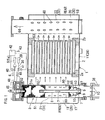
- Figs. 1 to 3 show an exhaust device for a diesel engine, in accordance with a first embodiment of the present invention.
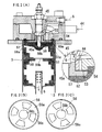
- Figs. 4 to 6 show an exhaust device for a diesel engine, in accordance with a second embodiment of the present invention.
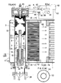
- Fig. 7 shows an exhaust device for a diesel engine, in accordance with a third embodiment of the present invention.
- liquid fuel 6 is supplied from a source 5 of the liquid fuel 6 to a gas generator 3, which converts the liquid fuel 6 into flammable gas 7.
- a supply passage 8 of the flammable gas 7 is conducted out of the gas generator 3.
- the supply passage 8 has a flammable-gas outlet 9 which communicates with an exhaust-gas route 1 upstream of a diesel-particulate-filter 2.
- the flammable gas 7 which flows out of the flammable-gas outlet 9 is burnt in exhaust gas 10 to generate combustion heat which in turn can burn fine particles of the exhaust gas 10 remaining at the filter 2.
- This exhaust device is connected to an exhaust-gas outlet 36 of an exhaust manifold for a diesel engine.
- the diesel-particulate-filter 2 is generally called as DPE and may have has a ceramic honeycomb structure.
- An oxidation catalyst is supported on the diesel-particulate-filter 2.
- a NOx-occlusion catalyst may be supported on the filter 2.
- a case 11 for containing the filter 2 accommodates part of the gas generator 3.
- the liquid fuel 6 is fuel from a fuel reservoir 5a of the diesel engine.
- the liquid fuel 6 is mixed with air 44 from a supercharger 39.
- a gap 53 through which the fuel passes, has an inlet side communicating with the fuel reservoir 5a of the diesel engine through a liquid-fuel supply passage 46 and with the supercharger 39 through an air-supply passage 38.
- the liquid-fuel supply passage 46 is provided with a liquid-fuel valve 40 and the air-supply passage 38 is provided with an air valve 41.
- Each of the valves 40 and 41 is associated with a back-pressure sensor 43 through a controller 42. If the filter 2 is clogged with fine particles of the exhaust gas, the back pressure increases. Then, based on the detection of this increase by the back-pressure sensor 43, the controller 42 opens the liquid-fuel valve 40 and the air valve 41 so as to supply the liquid fuel 6 and the air 44 to the gas generator 3.
- the liquid fuel 6 is vaporized to convert the liquid fuel 6 into flammable gas 7. This flammable gas 7 is fed into the exhaust-gas route 1.
- a catalyst 51a within a catalyst chamber 51 is an oxidation catalyst, which partially oxidizes the liquid fuel 6 to generate oxidation heat that vaporizes the remaining liquid fuel 6.
- the catalyst 51a may be a catalyst which comprises a catalytic component, such as platinum, supported on a metal substrate of a cubic mesh-structure.
- metal foam may be used for the substrate of the catalyst 51a.
- the metal foam is a metallic porous substance having the same cubic mesh-structure as a foamed resin, an example of which of which is a sponge, and is obtained by any suitable known method.
- the substrate of the catalyst 51a alumina pellets or the like metal pellets may be used.
- the mixing ratio of the liquid fuel 6 to the air 44 namely air-fuel ratio (O/C) is set in range generally centred on 0.6, for example from 0.4 to 0.8.
- the gas generator 3 vaporizes the liquid fuel 6 to convert it into the flammable gas 7
- the gas generator 3 may partly oxidize the liquid fuel 6 to convert it into a flammable gas 7 containing carbon monoxide and hydrogen.
- a partial-oxidation catalyst in the chamber 51 is utilized instead of the previously mentioned oxidation catalyst.
- Such a partial-oxidation catalyst may comprise a catalytic component, such as palladium or rhodium, supported on a metal substrate of a cubic mesh-structure.
- aluminas pellets or the like metal pellets may be employed.
- the mixing ratio of the liquid fuel 6 to the air 44 namely air-fuel ratio (O/C) may be set in a range about 1.3, for example from 1.0 to 1.6.
- the gas generator 3 is provided with a catalyst chamber 51.
- this catalyst chamber 51 has an upper portion at which a thermally conductive plate 52 is disposed.
- a fuel-passing gap 53 Formed along an upper surface of this thermally conductive plate 52 is a fuel-passing gap 53, to which the liquid fuel 6 and the air 44 are supplied.
- This fuel-passing gap 53 has a side opening to provide a fuel outlet 54 to the catalyst chamber 51 so as to conduct the catalytic combustion heat generated within the catalyst chamber 51 through the thermally conductive plate 52 to the fuel-passing gap 53.
- the glow plug 45 has an exothermic portion 45a projected downwards from a mid portion of the thermally conductive plate 52.
- the metal guide plate 56 is arranged below the thermally conductive plate 52 and is downwardly inclined from a peripheral portion 56a below the fuel outlet 54 to underneath the exothermic portion 45a of the glow plug 45, so that the liquid fuel 6 which flows from of the fuel outlet 54 impinges on the portion 56a of the guide plate 56 and approaches the exothermic portion 45a of the glow plug 45 through the guidance of the guide plate 56.
- a metal flame-quenching material 57 of a cubic mesh-structure occupies a space between the thermally conductive plate 52 and the guide plate 56.
- the glow plug 45 When the glow plug 45 generates heat, the heat generated by the glow plug 45 is conducted through the flame-quenching material 57 to the thermally conductive plate 52 and the guide plate 56. During the combustion of the catalyst 51a within the catalyst chamber 51, the catalytic combustion heat is conducted through the guide plate 56 and the flame-quenching material 57 to the thermally conductive plate 52.
- the glow plug 45 is associated with the controller 42 so as to generate heat for a predetermined period of time at the initial term of the gas generation.
- Metal foam is used for the flame-quenching material 57, but material made of stainless steel, and formed as 'wire-mesh', may be used.
- the guide plate 56 has an under-surface with which the catalyst 51a within the catalyst chamber 51 is brought into contact.
- a catalyst component is supported on the flame-quenching material 57.
- the glow plug 45 When the glow plug 45 generates heat, the heat generated by the glow plug 45 is conducted through the thermally conductive plate 52 to the fuel-passing gap 53.
- An oxidation-catalyst component is supported on the flame-quenching material 57.
- each of the guide plate 56 and the partition 58 is opened to provide a central aperture hole 56b and a central aperture 58b, respectively.
- Peripheral apertures 56c are regularly spaced around the central aperture 56b and a plurality apertures 58c are regularly spaced around the central aperture 58b.
- the apertures 56c and 58c of the guide plate 56 and the partition 58 are mutually staggered, when seen from above, so that the liquid fuel 6 flowed out of the fuel outlet 54 is prevented from flowing straight through both the apertures 56c and the apertures 58c in the mentioned order.
- Both the guide plate 56 and the partition 58 may be made of stainless steel.
- an oxidation catalyst 12 for accelerating the combustion of the flammable gas 7 is located between a flammable-gas outlet 9 and an inlet 2a of the filter 2.
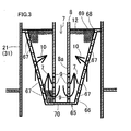
- the oxidation catalyst 12 is composed as follows. As shown in Fig. 3 , in order that the flammable gas 7 heated by the exothermic reaction within the gas generator 3 can flow out of the flammable-gas outlet 9 to the oxidation catalyst 12, the oxidation catalyst 12 occupies the case 65 and the flammable-gas outlet 9 opens into the oxidation catalyst 12.
- the case 65 has a peripheral wall 66 provided with a plurality of exhaust-gas inlets 67 and has a rear 68 formed with an exhaust-gas outlet 69.
- Exhaust-gas inlets 67 are disposed in the peripheral wall 66 of the oxidation-catalyst accommodating case 65.
- the exhaust-gas inlets 67 are located side by side in the peripheral wall 66 from the front end 70 of the case 65 to the rear end 68 thereof.
- the peripheral wall 66 of the 65 has a diameter which progressively increases from the front 70 to the rear end 68.
- the case 65 resembles a cup in the form of a truncated cone.
- the case 11 is a cylindrical, with end walls 17 and 18. An axial direction of this case 11 is taken as a front-to-rear direction.
- a inlet side 2a of the filter 2 is regarded as the 'front' and an an outlet side 2b is regarded as the 'rear'.
- Within the case 11 is disposed an exhaust-gas inlet chamber 19 in front of the filter 2 and an exhaust-gas outlet chamber 20 is arranged at the rear of the filter 2.
- the exhaust-gas inlet chamber 19 communicates with an exhaust-gas inlet pipe 21 and the exhaust-gas outlet chamber 20 communicates with an exhaust gas outlet pipe 22.
- the exhaust-gas inlet pipe 21 is inserted into the exhaust-gas inlet chamber 19 along a radial direction of the filter-containing case 11.
- the oxidation catalyst 12 and part of the gas generator 3 are disposed from the upstream side of the exhaust gas into the exhaust-gas inlet pipe 21 in the mentioned order.
- the flammable-gas supply passage 8 from the gas generator 3 extends into the oxidation
- An exhaust muffler 28 is utilized as the filter-containing case 11.
- the exhaust-gas inlet chamber 19 is composed of a first expansion chamber 29 and the exhaust-gas outlet chamber 20 is constructed by a final expansion chamber 30.
- the exhaust-gas inlet pipe 21 is formed from an exhaust-gas lead-in pipe 31 of the first expansion chamber 29 and the exhaust-gas outlet pipe 22 is composed of an exhaust-gas lead-out pipe 32 of the final expansion chamber 30.
- the exhaust gas 10 which passes through the exhaust-gas route 1 flows into the oxidation catalyst 12 and is mixed with the high-temperature flammable gas 7 and the mixture passes through the oxidation catalyst 12.
- the flammable gas 7 is oxidized (burnt) by the oxygen contained in the mixed exhaust gas 10 to produce oxidation heat (combustion heat) which heats the mixed exhaust gas 10.
- the exhaust gas 10 flows out of the oxidation catalyst 12 as shown by arrows 60 and further flows out of the outlet holes 47 of the exhaust-gas lead-in pipe 31 into the first expansion chamber 29. Then, as shown by arrows 62, it enters the filter 2 from the inlets 2a and passes through the filter. The exhaust gas 10 that has passed through the filter 2 flows from the outlets 2b of the filter 2 into the final expansion chamber 30 as shown by arrows 63. Thereafter, the gas flows from the inlet holes 48 of the exhaust-gas lead-in pipe 32 into the exhaust-gas lead-in pipe 32 and flows out of the exhaust-gas lead-out pipe 32 as shown by an arrow 64.
- the second embodiment as shown in Figs. 4 to 6 is different from the first embodiment as follows.
- the oxidation catalyst 12 is arranged outside the exhaust-gas inlet pipe 31, although it exists within the filter-containing case 11.
- an upstream oxidation-passage 14 is formed within the exhaust-gas passage 13 upstream of the oxidation catalyst 12 and is formed into a double-cylinder structure.
- the upstream oxidation-passage 14 accommodates an upstream oxidation-catalyst 15, on an upstream side of which the flammable-gas outlet 9 is opened toward the upstream oxidation-passage 14.
- the exhaust-gas passage 13 is the exhaust -gas inlet pipe 21.
- the upstream oxidation-passage has a sectional area set as follows. As shown in Fig. 4(B) , the upstream oxidation-passage 14 of the exhaust-gas passage 13 of the double-cylinder structure has a sectional area set to a fraction (such as 1/4) of the sectional area of the whole exhaust-gas passage 13 including the upstream oxidation-passage 14. In order to ensure the oxidation-acceleration function of the upstream oxidation-catalyst 15, it is desirable to set the sectional area of the upstream oxidation- passage 14 of the exhaust-gas passage 13 of double-cylinder structure within a range of 1/4 to 1/2 of the total sectional area of the exhaust-gas passage 13 including the upstream oxidation passage 14.
- the flammable-gas outlet and the upstream oxidation-passage are opened in the following direction.
- the flammable-gas lead-out pipe 8 oriented in the direction where the upstream oxidation-passage 14 is formed, has its terminal end 8a closed and has a peripheral wall near the terminal end 8a opened to provide the plurality of flammable-gas outlets 9 oriented radially of the upstream oxidation-passage 14.
- the upstream oxidation-passage 14 has its terminal end 14a closed and has a peripheral wall near the terminal end 14a, opened to form a plurality of upstream oxidation-passage outlets 16 oriented radially of a passage 4 in front of the oxidation-catalyst inlet.
- the high-temperature flammable gas 7 is fed from the flammable-gas supply passage 8 to the upstream oxidation-passage 14 within the exhaust-gas passage 13.
- part 10 of the exhaust gas shown by the arrows 10
- the flammable gas 7 is oxidized (burnt) by the oxygen contained in the mixed exhaust gas 10 to produce oxidation heat (combustion heat) which heats the mixed exhaust gas 10.
- the heated exhaust gas 10 flows out of the upstream oxidation-passage outlet 16; as shown by the arrows 35, and is mixed with the remaining exhaust gas 10 and 10 which did not flow into the upstream oxidation-passage 14.
- the mixture flows out of the outlet holes 47 and passes through the oxidation catalyst 12.
- the flammable gas 7 oxidized (burnt) by the upstream oxidation-catalyst 15 and remaining is oxidized (burnt) by the oxygen in the mixed exhaust gas 10 to produce oxidation (combustion) heat with which the mixed exhaust gas 10 is heated.
- the upstream oxidation catalyst 15 comprises a catalytic component supported on a substrate 25 formed by overlaying and winding a corrugated metal sheet 23 and a flat metal sheet 24.
- Each of the metal sheets 23 and 24 may be a stainless steel sheet having a thickness of 0.5 mm. Platinum may be used as the catalyst component.
- a relatively wide inter-catalyst passage 34 is formed and therefore even the upstream oxidation-passage 14 of a smaller diameter assures a sufficient sectional area of the inter-catalyst passage within the upstream oxidation-catalyst 15.
- the upstream oxidation-catalyst 15 may comprises a catalytic component supported on a substrate 27 formed from a metal mesh 26.
- This metal mesh 26 may be made of stainless steel and is generally called as "wire-mesh". Platinum may be used as the catalytic component.
- the oxidation catalyst 12 may comprise a catalytic component supported on a substrate 25 formed by overlaying and winding a corrugated metal sheet 23 and a flat metal sheet 24.
- Each of the metal sheets 23 and 24 may be a stainless steel sheet having a thickness of 0.5 mm. Platinum may be used as the catalyst component.
- the catalyst may comprise a catalytic component supported on a substrate 27 formed from a metal mesh 26. This metal mesh 26 may be made of stainless steel and is generally called as "wire-mesh". Platinum may be used as the catalyst component.
- the second embodiment is the same as the first embodiment except for the variants described above.
- the third embodiment shown in Fig. 7 is distinct from the first embodiment on the following point.
- Alumina pellets may be used for the substrate of the catalyst 51a within the catalyst chamber 51.
- the oxidation catalyst 12 is accommodated between the upstream oxidation catalyst 15 and the catalyst chamber 51 of the gas generator 3 within the exhaust-gas inlet pipe 21 of the filter-containing case 11.
- the flammable-gas lead-out passage 8 extends through the oxidation catalyst 12.
- the third embodiment is the same as the second embodiment except for the other constructions and functions.
Landscapes
- Engineering & Computer Science (AREA)
- Chemical & Material Sciences (AREA)
- Combustion & Propulsion (AREA)
- Mechanical Engineering (AREA)
- General Engineering & Computer Science (AREA)
- Processes For Solid Components From Exhaust (AREA)
- Exhaust Gas After Treatment (AREA)
Priority Applications (2)
| Application Number | Priority Date | Filing Date | Title |
|---|---|---|---|
| DE200760004186 DE602007004186D1 (de) | 2007-02-23 | 2007-02-23 | Abgasvorrichtung für einen Dieselmotor |
| EP20070250776 EP1961931B1 (de) | 2007-02-23 | 2007-02-23 | Abgasvorrichtung für einen Dieselmotor |
Applications Claiming Priority (1)
| Application Number | Priority Date | Filing Date | Title |
|---|---|---|---|
| EP20070250776 EP1961931B1 (de) | 2007-02-23 | 2007-02-23 | Abgasvorrichtung für einen Dieselmotor |
Publications (2)
| Publication Number | Publication Date |
|---|---|
| EP1961931A1 true EP1961931A1 (de) | 2008-08-27 |
| EP1961931B1 EP1961931B1 (de) | 2010-01-06 |
Family
ID=38196551
Family Applications (1)
| Application Number | Title | Priority Date | Filing Date |
|---|---|---|---|
| EP20070250776 Ceased EP1961931B1 (de) | 2007-02-23 | 2007-02-23 | Abgasvorrichtung für einen Dieselmotor |
Country Status (2)
| Country | Link |
|---|---|
| EP (1) | EP1961931B1 (de) |
| DE (1) | DE602007004186D1 (de) |
Cited By (4)
| Publication number | Priority date | Publication date | Assignee | Title |
|---|---|---|---|---|
| CN102510975A (zh) * | 2009-09-30 | 2012-06-20 | 株式会社Ihi | 点火装置 |
| CN103670607A (zh) * | 2012-09-11 | 2014-03-26 | 株式会社久保田 | 柴油机排气处理装置 |
| EP2554810A4 (de) * | 2010-03-31 | 2016-03-02 | Kubota Kk | Abgasbearbeitungsvorrichtung für einen dieselmotor |
| CN109248556A (zh) * | 2018-11-16 | 2019-01-22 | 李东东 | 工业废气处理装置 |
Citations (3)
| Publication number | Priority date | Publication date | Assignee | Title |
|---|---|---|---|---|
| DE20023560U1 (de) * | 2000-03-24 | 2005-01-27 | Huss Umwelttechnik Gmbh | Vorrichtung zum Reinigen von Abgasfiltern oder Partikelfiltern |
| US20050150219A1 (en) * | 2004-01-13 | 2005-07-14 | Crawley Wilbur H. | Method and apparatus for controlling the temperature of a fuel-fired burner of an emission abatement assembly |
| WO2007011113A1 (en) | 2005-07-22 | 2007-01-25 | Korea Institute Of Machinery And Materials | Inner flame burner for regeneration of diesel particulate filter |
-
2007
- 2007-02-23 EP EP20070250776 patent/EP1961931B1/de not_active Ceased
- 2007-02-23 DE DE200760004186 patent/DE602007004186D1/de active Active
Patent Citations (3)
| Publication number | Priority date | Publication date | Assignee | Title |
|---|---|---|---|---|
| DE20023560U1 (de) * | 2000-03-24 | 2005-01-27 | Huss Umwelttechnik Gmbh | Vorrichtung zum Reinigen von Abgasfiltern oder Partikelfiltern |
| US20050150219A1 (en) * | 2004-01-13 | 2005-07-14 | Crawley Wilbur H. | Method and apparatus for controlling the temperature of a fuel-fired burner of an emission abatement assembly |
| WO2007011113A1 (en) | 2005-07-22 | 2007-01-25 | Korea Institute Of Machinery And Materials | Inner flame burner for regeneration of diesel particulate filter |
Cited By (8)
| Publication number | Priority date | Publication date | Assignee | Title |
|---|---|---|---|---|
| CN102510975A (zh) * | 2009-09-30 | 2012-06-20 | 株式会社Ihi | 点火装置 |
| EP2484973A4 (de) * | 2009-09-30 | 2013-03-13 | Ihi Corp | Zündvorrichtung |
| CN102510975B (zh) * | 2009-09-30 | 2015-04-22 | 株式会社Ihi | 点火装置 |
| US9395083B2 (en) | 2009-09-30 | 2016-07-19 | Ihi Corporation | Ignition device |
| EP2554810A4 (de) * | 2010-03-31 | 2016-03-02 | Kubota Kk | Abgasbearbeitungsvorrichtung für einen dieselmotor |
| CN103670607A (zh) * | 2012-09-11 | 2014-03-26 | 株式会社久保田 | 柴油机排气处理装置 |
| CN103670607B (zh) * | 2012-09-11 | 2017-09-22 | 株式会社久保田 | 柴油机排气处理装置 |
| CN109248556A (zh) * | 2018-11-16 | 2019-01-22 | 李东东 | 工业废气处理装置 |
Also Published As
| Publication number | Publication date |
|---|---|
| EP1961931B1 (de) | 2010-01-06 |
| DE602007004186D1 (de) | 2010-02-25 |
Similar Documents
| Publication | Publication Date | Title |
|---|---|---|
| EP2025890B1 (de) | Abgasvorrichtung für einen Dieselmotor | |
| JP4677418B2 (ja) | ディーゼルエンジンの排気装置 | |
| US20060075744A1 (en) | Apparatus and method for regenerating a particulate filter of an exhaust system of an internal combustion engine | |
| US7021048B2 (en) | Combination emission abatement assembly and method of operating the same | |
| US6959542B2 (en) | Apparatus and method for operating a fuel reformer to regenerate a DPNR device | |
| US7814746B2 (en) | Exhaust device for a diesel engine | |
| US20030200742A1 (en) | Apparatus and method for regenerating a particulate filter of an exhaust system of an internal combustion engine | |
| US7014930B2 (en) | Apparatus and method for operating a fuel reformer to generate multiple reformate gases | |
| EP1961931B1 (de) | Abgasvorrichtung für einen Dieselmotor | |
| US7464539B2 (en) | Method and apparatus for supplying air to emission abatement device by use of turbocharger | |
| US6698193B2 (en) | Exhaust gas cleaning system for an internal combustion engine, for a motor vehicle | |
| JP4674189B2 (ja) | ディーゼルエンジンの排気装置 | |
| JP5322465B2 (ja) | 改質装置の燃焼装置、改質装置および燃料電池システム | |
| JP2021131169A (ja) | 燃焼器、改質装置及び改質システム | |
| JP2005214543A (ja) | 燃焼装置及び燃料電池に用いられる水素供給装置 | |
| JP2008232061A (ja) | ディーゼルエンジンの排気装置 | |
| JP2007042597A (ja) | 触媒燃焼器 | |
| JP4794594B2 (ja) | ディーゼルエンジンの排気装置 | |
| JP2007239734A (ja) | ディーゼルエンジンの排気装置 | |
| CN101265823B (zh) | 用于柴油机的排气装置 | |
| KR101318014B1 (ko) | 디젤엔진의 배기장치 | |
| US20080020333A1 (en) | Dual reaction zone fuel reformer and associated method | |
| KR100866329B1 (ko) | 플라즈마 버너 및 매연여과장치 | |
| JP2019120135A (ja) | エンジンの排気処理装置 | |
| JP2019120132A (ja) | エンジンの排気処理装置 |
Legal Events
| Date | Code | Title | Description |
|---|---|---|---|
| PUAI | Public reference made under article 153(3) epc to a published international application that has entered the european phase |
Free format text: ORIGINAL CODE: 0009012 |
|
| AK | Designated contracting states |
Kind code of ref document: A1 Designated state(s): AT BE BG CH CY CZ DE DK EE ES FI FR GB GR HU IE IS IT LI LT LU LV MC NL PL PT RO SE SI SK TR |
|
| AX | Request for extension of the european patent |
Extension state: AL BA HR MK RS |
|
| 17P | Request for examination filed |
Effective date: 20081027 |
|
| 17Q | First examination report despatched |
Effective date: 20081202 |
|
| AKX | Designation fees paid |
Designated state(s): DE FR GB IT |
|
| GRAP | Despatch of communication of intention to grant a patent |
Free format text: ORIGINAL CODE: EPIDOSNIGR1 |
|
| GRAS | Grant fee paid |
Free format text: ORIGINAL CODE: EPIDOSNIGR3 |
|
| GRAA | (expected) grant |
Free format text: ORIGINAL CODE: 0009210 |
|
| AK | Designated contracting states |
Kind code of ref document: B1 Designated state(s): DE FR GB IT |
|
| REG | Reference to a national code |
Ref country code: GB Ref legal event code: FG4D |
|
| REF | Corresponds to: |
Ref document number: 602007004186 Country of ref document: DE Date of ref document: 20100225 Kind code of ref document: P |
|
| PLBE | No opposition filed within time limit |
Free format text: ORIGINAL CODE: 0009261 |
|
| STAA | Information on the status of an ep patent application or granted ep patent |
Free format text: STATUS: NO OPPOSITION FILED WITHIN TIME LIMIT |
|
| 26N | No opposition filed |
Effective date: 20101007 |
|
| PGRI | Patent reinstated in contracting state [announced from national office to epo] |
Ref country code: IT Effective date: 20110501 |
|
| REG | Reference to a national code |
Ref country code: FR Ref legal event code: PLFP Year of fee payment: 10 |
|
| REG | Reference to a national code |
Ref country code: FR Ref legal event code: PLFP Year of fee payment: 11 |
|
| REG | Reference to a national code |
Ref country code: FR Ref legal event code: PLFP Year of fee payment: 12 |
|
| PGFP | Annual fee paid to national office [announced via postgrant information from national office to epo] |
Ref country code: DE Payment date: 20180214 Year of fee payment: 12 Ref country code: GB Payment date: 20180221 Year of fee payment: 12 |
|
| PGFP | Annual fee paid to national office [announced via postgrant information from national office to epo] |
Ref country code: FR Payment date: 20180111 Year of fee payment: 12 Ref country code: IT Payment date: 20180221 Year of fee payment: 12 |
|
| REG | Reference to a national code |
Ref country code: DE Ref legal event code: R119 Ref document number: 602007004186 Country of ref document: DE |
|
| GBPC | Gb: european patent ceased through non-payment of renewal fee |
Effective date: 20190223 |
|
| PG25 | Lapsed in a contracting state [announced via postgrant information from national office to epo] |
Ref country code: DE Free format text: LAPSE BECAUSE OF NON-PAYMENT OF DUE FEES Effective date: 20190903 Ref country code: GB Free format text: LAPSE BECAUSE OF NON-PAYMENT OF DUE FEES Effective date: 20190223 |
|
| PG25 | Lapsed in a contracting state [announced via postgrant information from national office to epo] |
Ref country code: IT Free format text: LAPSE BECAUSE OF NON-PAYMENT OF DUE FEES Effective date: 20190223 Ref country code: FR Free format text: LAPSE BECAUSE OF NON-PAYMENT OF DUE FEES Effective date: 20190228 |