EP1962017B1 - Vorrichtung zur Vermeidung einer Abgasrückströmung bei einem Heizkessel - Google Patents
Vorrichtung zur Vermeidung einer Abgasrückströmung bei einem Heizkessel Download PDFInfo
- Publication number
- EP1962017B1 EP1962017B1 EP08000896.4A EP08000896A EP1962017B1 EP 1962017 B1 EP1962017 B1 EP 1962017B1 EP 08000896 A EP08000896 A EP 08000896A EP 1962017 B1 EP1962017 B1 EP 1962017B1
- Authority
- EP
- European Patent Office
- Prior art keywords
- flap part
- holder
- supply air
- flap
- air pipeline
- Prior art date
- Legal status (The legal status is an assumption and is not a legal conclusion. Google has not performed a legal analysis and makes no representation as to the accuracy of the status listed.)
- Not-in-force
Links
- 238000007789 sealing Methods 0.000 claims description 23
- 239000000463 material Substances 0.000 claims description 11
- 239000013013 elastic material Substances 0.000 claims description 6
- 229920003023 plastic Polymers 0.000 claims description 6
- 239000004033 plastic Substances 0.000 claims description 6
- 230000000903 blocking effect Effects 0.000 claims description 4
- 238000010348 incorporation Methods 0.000 claims 1
- 239000007789 gas Substances 0.000 description 5
- 230000008859 change Effects 0.000 description 4
- 238000009434 installation Methods 0.000 description 4
- 230000005484 gravity Effects 0.000 description 3
- 238000011144 upstream manufacturing Methods 0.000 description 3
- 230000008901 benefit Effects 0.000 description 2
- 238000011161 development Methods 0.000 description 2
- 230000018109 developmental process Effects 0.000 description 2
- 230000000694 effects Effects 0.000 description 2
- 238000004519 manufacturing process Methods 0.000 description 2
- 101001017827 Mus musculus Leucine-rich repeat flightless-interacting protein 1 Proteins 0.000 description 1
- 239000004698 Polyethylene Substances 0.000 description 1
- HCHKCACWOHOZIP-UHFFFAOYSA-N Zinc Chemical compound [Zn] HCHKCACWOHOZIP-UHFFFAOYSA-N 0.000 description 1
- 230000032683 aging Effects 0.000 description 1
- 229910052782 aluminium Inorganic materials 0.000 description 1
- XAGFODPZIPBFFR-UHFFFAOYSA-N aluminium Chemical compound [Al] XAGFODPZIPBFFR-UHFFFAOYSA-N 0.000 description 1
- 230000015572 biosynthetic process Effects 0.000 description 1
- 238000005520 cutting process Methods 0.000 description 1
- 230000006735 deficit Effects 0.000 description 1
- 238000006073 displacement reaction Methods 0.000 description 1
- 230000004941 influx Effects 0.000 description 1
- 238000001746 injection moulding Methods 0.000 description 1
- 230000007774 longterm Effects 0.000 description 1
- 239000012528 membrane Substances 0.000 description 1
- 229910052751 metal Inorganic materials 0.000 description 1
- 239000002184 metal Substances 0.000 description 1
- -1 polyethylene Polymers 0.000 description 1
- 229920000573 polyethylene Polymers 0.000 description 1
- 229920003225 polyurethane elastomer Polymers 0.000 description 1
- 230000009467 reduction Effects 0.000 description 1
- 238000007493 shaping process Methods 0.000 description 1
- 239000007921 spray Substances 0.000 description 1
- 229910052725 zinc Inorganic materials 0.000 description 1
- 239000011701 zinc Substances 0.000 description 1
Images

Classifications
-
- F—MECHANICAL ENGINEERING; LIGHTING; HEATING; WEAPONS; BLASTING
- F23—COMBUSTION APPARATUS; COMBUSTION PROCESSES
- F23L—SUPPLYING AIR OR NON-COMBUSTIBLE LIQUIDS OR GASES TO COMBUSTION APPARATUS IN GENERAL ; VALVES OR DAMPERS SPECIALLY ADAPTED FOR CONTROLLING AIR SUPPLY OR DRAUGHT IN COMBUSTION APPARATUS; INDUCING DRAUGHT IN COMBUSTION APPARATUS; TOPS FOR CHIMNEYS OR VENTILATING SHAFTS; TERMINALS FOR FLUES
- F23L11/00—Arrangements of valves or dampers after the fire
- F23L11/005—Arrangements of valves or dampers after the fire for closing the flue during interruption of burner function
-
- F—MECHANICAL ENGINEERING; LIGHTING; HEATING; WEAPONS; BLASTING
- F23—COMBUSTION APPARATUS; COMBUSTION PROCESSES
- F23L—SUPPLYING AIR OR NON-COMBUSTIBLE LIQUIDS OR GASES TO COMBUSTION APPARATUS IN GENERAL ; VALVES OR DAMPERS SPECIALLY ADAPTED FOR CONTROLLING AIR SUPPLY OR DRAUGHT IN COMBUSTION APPARATUS; INDUCING DRAUGHT IN COMBUSTION APPARATUS; TOPS FOR CHIMNEYS OR VENTILATING SHAFTS; TERMINALS FOR FLUES
- F23L13/00—Construction of valves or dampers for controlling air supply or draught
- F23L13/02—Construction of valves or dampers for controlling air supply or draught pivoted about a single axis but having not other movement
Definitions
- the invention relates to a device for preventing an exhaust gas recirculation in a boiler in the overpressure operation, wherein a plurality of boilers have a common exhaust pipe, and a supply air line of each boiler has a cross-section occluding blocking member, wherein the blocking member is designed as a non-return valve, wherein the non-return valve Has at least one flap part which is articulated pivotably on a frame-like attitude, and wherein the holder is designed as insertable into the supply air line.
- the DE202006010099 U1 discloses a device for preventing backflow of exhaust gas in a boiler according to the preamble of claim 1.
- the invention has for its object to provide a device which ensures a permanent sealing function and is simple and therefore inexpensive to produce.
- the non-return valve according to the invention is particularly reliable.
- a frame-like holder in conjunction with the hinged thereto flap part, it is possible to form a device according to the invention, which, due to their simple design, in the supply air lines a variety of different blower burners can be integrated in an advantageous manner.
- the holder is designed as a built-in insert, already in operation boilers can be easily retrofitted with such inventively designed devices.
- the flap member may have a rectangular orientation to the flow direction in its closed position and is connected via a pivot bearing with the holder, which for the purpose of smooth running has a radial clearance to allow an advantageous free pivoting movement of the flap part.
- the installation position of the frame-like holder can be aligned both horizontally and vertically.
- the device according to the invention has a tumbler for the flap part.
- the tumbler advantageously ensures that the flap portion, after the negative pressure and thus the flow in the supply air line generating fan burner of the boiler has been turned off, is held in its closed position and completely closes the preferably circular opening of the frame-like support.
- the tumbler can be done for example by means of a spring element which engages with a predetermined spring force on the flap part and a corresponding contact pressure between Damper and bracket causes. It is also conceivable to use movably guided closing weights, such as a ball, on the flap part of the device for forming a tumbler. The movable closing weights cause a shift of the center of gravity of the flap part during the opening movement in the direction of its pivot bearing.
- the design of the tumbler as a magnetic closure provides a structurally simple way to implement a tumbler. Unlike a spring element acting on the flap part, a magnetic closure preferably exerts its greatest holding force directly in or close to the closed position of the flap part. However, as soon as the holding force between the permanent magnet and the counterpart arranged on the flap part is overcome at the beginning of an opening movement of the flap part, the flap part can move freely. Furthermore, with the aid of the permanent magnet used and preferably designed as a metal part counterpart on the flap part, wherein the permanent magnet can also be arranged on the flap part and the counterpart on the frame-like support, ensure a reliable long-term function of the tumbler. It is of course also possible to use other, a holding force generating functional parts in place of the permanent magnet.
- the flap level of the flap part can be aligned in its closed position at an angle of 40 ° to 70 ° to the longitudinal axis of the holder inserted in the supply air line.
- the oblique orientation of the flap plane of the flap part to the longitudinal axis of the frame-like holder ensures that, in particular in a horizontally extending supply air line, always a cross-sectional area of the supply air line By means of the flap part obstructing closed position is given. Due to the oblique orientation of the flap plane, the dead weight of the flap part generates a force acting between the contact surfaces of the holder and the flap part contact pressure, with the help of operating shutdown at the same time an advantageous sealing of the contact surfaces is effected together.
- the angle between the flap plane of the flap part and extending in the central center of the holder central longitudinal axis of the holder is preferably about 65 °.
- the flap part is equipped with closing weights.
- closing weights allows in an advantageously simple manner an increase in the dead weight of the flap part, so that the return movement of the flap part is done safely in its closed position after switching off the fan burner.
- the number or size of the closing weights used can vary with regard to the necessary closing force and the associated operating behavior of a designed as a check valve device for flow control.
- the closing weights are preferably arranged outside the center of gravity of the flap part, in particular in a region approximated to the pivot bearing, in such a way that an optimum sealing effect is always ensured in the region of the play-bearing pivot bearing.
- the flap part and the flap part associated with the holder have abuttable sealing surfaces.
- the sealing surfaces cause a seal between the contact surfaces of the flap part and the holder is improved; because the trained as sealing surfaces contact surfaces ensure optimum sealing effect when the flap part of the device according to the invention is in the closed position.
- the surface of the flap part and the Holder can be processed in the region of their sealing surfaces, for example by means of a cutting process, so that each of the sealing surfaces receives a corresponding surface quality for optimum sealing function.
- the material for the sealing surface of the holder is a soft-elastic material.
- the use of a soft elastic material for forming a sealing surface of the holder has the advantage that it, due to its elastic properties, can compensate for certain manufacturing tolerances, whereby an optimal seal between the flap part and holder is guaranteed.
- the soft elastic material can be in an advantageously simple manner to appropriate contours surfaces having, for example, spray.
- a flexible material for example, a polyurethane elastomer can be used.
- the frame-like support is advantageously an annular body, whose in the supply air line projecting, upstream surfaces have a streamlined shape. Due to the flow-favorable shaping of the supply air line projecting, upstream surfaces of the holder, the flow or pressure losses occurring in the supply air line are kept as low as possible. It is of course also possible to provide instead of a circular ring body a square configuration of the holder, which can then be integrated into, for example, a rectangular Zu Kunststoff- or suction of the respective boiler.
- the holder has a receptacle, and the receptacle comprises at least one guide for the permanent magnet.
- the permanent magnet can advantageously be easily along the particular guide surfaces having the inner lateral surface of the socket move.
- a displacement of the permanent magnet in the receptacle causes a change in distance and thus a corresponding enlargement or reduction of the force acting on the counterpart, and thus the flap part, magnetic holding force.
- the individual adjustability of the holding force is particularly advantageous when the device according to the invention is to show a matched to the corresponding performance characteristics of a respective associated blower burner performance.
- the receptacle is preferably arranged parallel to the longitudinal axis of the supply air line in the annular body of the holder.
- the material for the flap part is in particular plastic, wherein the application is preferably a polyethylene.
- the material used has advantageous properties in terms of its low density and the associated low dead weight, so that can be safely folded out by means of the incoming air through the supply air supply line made of plastic flap part of the flow cross section of the supply air line.
- the material for the holder is a plastic.
- the plastic has the advantage that it can be processed by means of advantageous manufacturing processes, such as injection molding. Of course, other pourable materials can be used, especially zinc and aluminum.
- the supply air line has at least one piece of pipe, in which the check valve is received, wherein the pipe wall of the pipe section has outwardly directed bulges for the pivotable flap part.
- the training of the outside directed bulges in the pipe wall of the pipe section ensures that the flap part of the check valve can perform its folding movements without hindrance.
- the flap part can be folded by these bulges preferably in a position approximated to the pipe wall.
- the holder has at least one positioning aid for a predetermined installation position in the supply air line. With the help of the positioning a corresponding orientation of the device during installation in a piece of pipe of the supply air line. This ensures that the flap part after installation is at the correct functional angle to the inflow of incoming air.
- the positioning can be designed in particular as located on the outer contour of the holder, protruding positive-locking parts, which engage in associated, embedded in the wall of the supply air intake recordings.
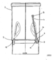
- Fig. 1 shows a check valve 1, which is arranged in particular in a pipe section 2 of a supply air line.
- the non-return flap 1 has a frame-like holder 3 designed here as an annular body, on which a flap part 4 is articulated in a hinged manner.
- the flap part is arranged in its closed position transversely to the flow direction of the supply air line.
- An arrangement at a predetermined angle to its longitudinal axis is also readily possible.
- the flap part 4 is articulated on one side at one point of its circumference via a pivot bearing 5, so that the flap part 4 is free to move freely in the flow direction of the supply air.
- the flap part 4 If the supply of supply air is stopped, then the flap part 4 returns to its closed position and prevents backflow of exhaust gases against the flow direction of the supply air.
- the check valve 1 is further equipped with a designed as a magnetic closure tumbler 8 for the flap part 4, which exerts a predetermined holding force on the flap part 4.
- the tumbler 8 has a permanent magnet 9, which is associated with a arranged on the flap part 4 counterpart 10.
- the permanent magnet 9 and the counterpart 10 are in particular in the closed position of the flap part 4 together in a holding operative connection.
- Fig. 2 shows in particular a sectional view of the check valve 1 and the check valve 1 receiving pipe section 2 of the supply air line.
- upstream surfaces 11 of the holder 3 have a streamlined shape.
- the tube piece has outwardly directed bulges 12, 13 (FIG. Fig. 1 ) for the pivoting Flap part 4 on.
- the bulges 12, 13 increase the opening angle of the flap part and limit it at the same time in a predetermined manner, so that the flap part coincides when switching off the fan burner (flow arrest) by gravity again. Opening the flap part 4 guaranteed.
- the flap part 4 is additionally provided with closing weights 14, which ensure an optimal seal of the flap part 4 in the region of preferably a game-bearing pivot bearing 5 in case of interruption of the supply air.
- the holder 3 has a receptacle 15 in the form of a plug-in socket, in which the permanent magnet 9 is held in a sliding manner.
- About the recording 15 can be a stepless change of the force acting between the permanent magnet 9 and the counterpart 10 holding force make, whereby an optimal adjustability of the tumbler 8 is given with respect to a predetermined performance of the check valve 1.
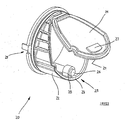
- Fig. 3 another embodiment of a check valve 20 is shown.
- the flap plane of the flap member 21 is aligned in the closed position at a predetermined angle to the longitudinal axis of the flap member receiving bracket 22.
- Both the flap part 21 and the holder 22 have sealing surfaces 23, 24 which can be brought into abutment with each other, wherein in particular the sealing surface 23 of the holder consists of a soft-elastic material.
- the non-return valve 20 is also provided with a designed as a magnetic closure tumbler 25 for the flap part.
- the tumbler having a permanent magnet 26 is associated with a metallic counterpart 27, which is arranged on the flap part 21.
- the check valve 20 is equipped with a positioning aid 29, which always ensures a defined mounting position of the check valve in the supply air line of a boiler.
- the positioning aid 29 is a notch, which is introduced into a circumferential projection of the holder designed as a ring body. In the notch can engage a correspondingly formed on the supply air pipe fitting.
Landscapes
- Engineering & Computer Science (AREA)
- Chemical & Material Sciences (AREA)
- Combustion & Propulsion (AREA)
- Mechanical Engineering (AREA)
- General Engineering & Computer Science (AREA)
- Feeding And Controlling Fuel (AREA)
- Incineration Of Waste (AREA)
- Lift Valve (AREA)
Description
- Die Erfindung bezieht sich auf eine Vorrichtung zur Vermeidung einer Abgasrückströmung bei einem Heizkessel im Überdruckbetrieb, wobei mehrere Heizkessel eine gemeinsame Abgasleitung aufweisen, und eine Zuluft-Leitung jedes Heizkessels ein ihren Querschnitt verschließendes Sperrorgan aufweist, wobei das Sperrorgan als Rückschlagklappe ausgebildet ist, wobei die Rückschlagklappe mindestens ein Klappenteil aufweist, welches an einer rahmenartigen Haltung schwenkbeweglich angelenkt ist, und wobei die Halterung als in die Zuluft-Leitung einbaubarer Einsatz ausgebildet ist. Die
DE202006010099 U1 offenbart eine Vorrichtung zur Vermeidung einer Abgasrückströmung bei einem Heizkessel gemäß den Oberbegriff des Anspruchs 1. Bei derartigen Vorrichtungen können zum Beispiel wechselnde Temperaturen bzw. die natürliche Alterung des Materials, eine Verformung oder Versprödung der elastischen Membran verursachen. Im Bedarfsfall könnte dann eine sichere Anlage des Dichtelementes an der Dichtfläche nicht mehr gegeben sein und ein unerwünschtes Einströmen von Abgasen in den Aufstellraum des Heizkessels erfolgen, wenn der Betrieb eines oder mehrerer der an eine gemeinsame Abgasleitung angeschlossenen Heizkessels unterbrochen ist. - Weitere gattungsbildende Vorrichtungen sind in der
EP 1 544 544 A1 und in derWO 03/036 181 A1 - Der Erfindung liegt die Aufgabe zugrunde, eine- Vorrichtung zu schaffen, welche eine dauerhaft abdichtende Funktion sicherstellt und einfach und somit kostengünstig herstellbar ist.
- Die Lösung der Aufgabe erfolgt erfindungsgemäß durch eine Vorrichtung mit den Merkmalen des Schutzanspruches 1. Vorteilhafte Weiterbildungen und Ausgestaltungen der Erfindung sind in den Ansprüchen 2 bis 11 angegeben.
- Mit der Ausbildung des Sperrorganes als in der Zuluft-Leitung sitzende Rückschlagklappe, ist eine vorteilhaft einfache und zugleich betriebssichere Abdichtfunktion der Vorrichtung zur Vermeidung von Abgasrückströmungen für einen mit einem Gebläsebrenner ausgerüsteten Heizkessel gegeben. Eine Rückschlagklappe ist unkompliziert, also konstruktiv einfach und als steife Klappe relativ formstabil. Auf die Rückschlagklappe einwirkende Temperaturwechsel bzw. Versprödungen des verwendeten Materials werden kaum Einfluß auf deren Form nehmen und es tritt somit keine Beeinträchtigung der abdichtenden Funktion ein.
- Die erfindungsgemäße Rückschlagklappe wirkt besonders betriebssicher.
- Durch die Verwendung einer rahmenartigen Halterung in Verbindung mit dem daran angelenkten Klappenteil ist es möglich, eine erfindungsgemäße Vorrichtung auszubilden, die, aufgrund ihrer konstruktiv einfachen Ausgestaltung, in die Zuluft-Leitungen einer Vielzahl unterschiedlichster Gebläsebrenner auf vorteilhafte Weise integriert werden können. Da die Halterung als einbaubarer Einsatz ausgebildet ist, lassen sich bereits in Betrieb befindliche Heizkessel mit derartig erfindungsgemäß ausgebildeten Vorrichtungen problemlos nachrüsten. Das Klappenteil kann in seiner Schließstellung eine rechtwinklige Ausrichtung zur Strömungsrichtung aufweisen und ist über ein Drehlager mit der Halterung verbunden, welches zwecks Leichtgängigkeit ein radiales Spiel aufweist, um eine vorteilhaft freie Schwenkbewegung des Klappenteiles zu ermöglichen. Die Einbaulage der rahmenartigen Halterung kann sowohl horizontal als auch vertikal ausgerichtet sein.
- Damit stets eine dichtende Anlage des Klappenteiles mit der Halterung gegeben ist, weist die erfindungsgemäße Vorrichtung eine Zuhaltung für das Klappenteil auf. Die Zuhaltung stellt auf vorteilhafte Weise sicher, dass das Klappenteil, nachdem der einen Unterdruck und somit die Strömung in der Zuluft-Leitung erzeugende Gebläsebrenner des Heizkessels abgeschaltet wurde, in seiner Schließstellung gehalten wird und die vorzugsweise kreisrunde Öffnung der rahmenartigen Halterung vollständig verschließt. Die Zuhaltung kann beispielsweise mit Hilfe eines Federelementes erfolgen, welches mit einer vorbestimmten Federkraft am Klappenteil angreift und eine entsprechende Anpreßkraft zwischen Klappenteil und Halterung bewirkt. Es ist ebenfalls denkbar, beweglich geführte Schließgewichte, wie z.B. eine Kugel, am Klappenteil der Vorrichtung zur Ausbildung einer Zuhaltung zu verwenden. Die beweglichen Schließgewichte bewirken eine Verlagerung des Schwerpunktes des Klappenteiles während der Öffnungsbewegung in Richtung seines Drehlagers.
- Die Ausbildung der Zuhaltung als Magnetverschluss stellt eine konstruktiv einfache Möglichkeit zur Umsetzung einer Zuhaltung dar. Anders als ein am Klappenteil angreifendes Federelement, übt ein Magnetverschluss mit Vorteil unmittelbar in, bzw. nahe der Schließstellung des Klappenteiles seine größte Haltekraft aus. Sobald jedoch die Haltekraft zwischen Permanentmagnet und dem am Klappenteil angeordneten Gegenstück zu Beginn einer Öffnungsbewegung des Klappenteiles überwunden ist, läßt sich das Klappenteil frei bewegen. Des Weiteren lässt sich mit Hilfe des eingesetzten Permanentmagneten und dem vorzugsweise als Metallteil ausgebildeten Gegenstück am Klappenteil, wobei der Permanentmagnet auch am Klappenteil und das Gegenstück an der rahmenartigen Halterung angeordnet sein kann, eine betriebssichere Langzeitfunktion der Zuhaltung gewährleisten. Es ist selbstverständlich auch möglich, an Stelle des Permanentmagneten andere, eine Haltekraft erzeugende Funktionsteile einzusetzen.
- Die Klappenebene des Klappenteiles kann in seiner Schließstellung in einem Winkel von 40° bis 70° zur Längsachse der in die Zuluft-Leitung eingesetzten Halterung ausgerichtet sein. Die schräge Ausrichtung der Klappenebene des Klappenteiles zur Längsachse der rahmenartigen Halterung stellt sicher, dass, insbesondere bei einer horizontal verlaufenden Zuluft-Leitung, stets eine die Querschnittsfläche der Zuluft-Leitung mittels des Klappenteils versperrende Schließstellung gegeben ist. Durch die schräge Ausrichtung der Klappenebene erzeugt das Eigengewicht des Klappenteiles eine zwischen den Anlageflächen der Halterung und des Klappenteiles wirkende Anpreßkraft, mit deren Hilfe bei Betriebsabschaltung gleichzeitig eine vorteilhafte Abdichtung der Anlageflächen aneinander bewirkt wird. Der Winkel zwischen der Klappenebene des Klappenteiles und der im mittigen Zentrum der Halterung verlaufenden Mittellängsachse der Halterung beträgt vorzugsweise etwa 65°.
- Nach einer anderen Weiterbildung der Erfindung ist vorgesehen, dass das Klappenteil mit Schließgewichten ausgerüstet ist. Der Einsatz von Schließgewichten ermöglicht auf vorteilhaft einfache Weise eine Erhöhung des Eigengewichts des Klappenteiles, so dass die Rückbewegung des Klappenteiles in seine Schließstellung nach dem Abschalten des Gebläsebrenners sicher erfolgt. Die Anzahl bzw. die Größe der eingesetzten Schließgewichte kann hinsichtlich der notwendigen Schließkraft und dem damit verbundenen Betriebsverhalten einer als Rückschlagklappe ausgebildeten Vorrichtung zur Strömungssicherung variieren. Die Schließgewichte sind vorzugsweise außerhalb des Schwerpunktes des Klappenteiles angeordnet, insbesondere in einem an das Drehlager angenäherten Bereich, derart, dass stets eine optimale Dichtwirkung im Bereich des spielbehafteten Drehlagers gewährleistet ist.
- Das Klappenteil und die dem Klappenteil zugeordnete Halterung weisen miteinander in Anlage bringbare Dichtflächen auf. Die Dichtflächen bewirken, dass eine Abdichtung zwischen den Anlageflächen des Klappenteiles und der Halterung verbessert ist; denn die als Dichtflächen ausgebildeten Anlageflächen gewährleisten eine optimale Dichtwirkung, wenn sich das Klappenteil der erfindungsgemäßen Vorrichtung in der Schließstellung befindet. Die Oberfläche des Klappenteiles und der Halterung können im Bereich ihrer Dichtflächen beispielsweise mittels eines spanenden Verfahrens bearbeitet sein, so dass jede der Dichtflächen eine entsprechende Oberflächengüte für eine optimale Abdichtfunktion erhält.
- Nach einer Weiterbildung der Erfindung ist vorgesehen, dass der Werkstoff für die Dichtfläche der Halterung ein weichelastischer Werkstoff ist. Der Einsatz eines weichelastischen Werkstoffes zur Ausbildung einer Dichtfläche der Halterung hat den Vorteil, dass er, aufgrund seiner elastischen Eigenschaften, bestimmte Fertigungstoleranzen ausgleichen kann, wodurch eine optimale Abdichtung zwischen Klappenteil und Halterung gewährleistet ist. Des weiteren läßt sich der weichelastische Werkstoff auf vorteilhaft einfache Weise an entsprechende Konturen aufweisende Oberflächen anformen, zum Beispiel anspritzen. Als weichelastischer Werkstoff kann zum Beispiel ein Polyurethanelastomer eingesetzt werden.
- Die rahmenartige Halterung ist mit Vorteil ein Ringkörper, dessen in die Zuluft-Leitung vorstehenden, anströmseitigen Flächen eine strömungsgünstige Formgebung aufweisen. Durch die strömungsgünstige Formgebung der in die Zuluft-Leitung vorstehenden, anströmseitigen Flächen der Halterung werden die in der Zuluft-Leitung auftretenden Strömungs- bzw. Druckverluste so gering wie möglich gehalten. Es ist selbstverständlich auch möglich, anstelle eines kreisförmigen Ringkörpers eine eckige Ausbildung der Halterung vorzusehen, welche sich dann in beispielsweise eine rechteckige Zuluft- bzw. Ansaugleitung des jeweiligen Heizkessels integrieren läßt.
- Die Halterung weist eine Aufnahme auf, und die Aufnahme umfaßt mindestens eine Führung für den Permanentmagneten. Mittels einer beispielsweise als Steckbuchse ausgebildeten Aufnahme, welche gleichzeitig als Führung für den Permanentmagneten dient, läßt sich der Permanentmagnet vorteilhaft einfach längs der insbesondere Führungsflächen aufweisenden inneren Mantelfläche der Steckbuchse verschieben. Eine Verschiebung des Permanentmagneten in der Aufnahme bewirkt eine Abstandsveränderung und somit eine entsprechende Vergrößerung bzw. Verkleinerung der auf das Gegenstück, und somit auch das Klappenteil, einwirkenden magnetischen Haltekraft. Die individuelle Einstellbarkeit der Haltekraft ist insbesondere dann von Vorteil, wenn die erfindungsgemäße Vorrichtung ein auf die entsprechende Leistungscharakteristik eines jeweils zugeordneten Gebläsebrenners abgestimmtes Betriebsverhalten zeigen soll. Die Aufnahme ist vorzugsweise parallel zur Längsachse der Zuluft-Leitung im Ringkörper der Halterung angeordnet.
- Der Werkstoff für das Klappenteil ist insbesondere Kunststoff, wobei zur Anwendung bevorzugt ein Polyethylen kommt. Der eingesetzte Werkstoff weist vorteilhafte Eigenschaften hinsichtlich seiner geringen Dichte und des damit verbundenen niedrigen Eigengewichts auf, so dass sich mittels der durch die Zuluft-Leitung einströmenden Zuluft das aus Kunststoff ausgebildete Klappenteil aus dem Strömungsquerschnitt der Zuluft-Leitung sicher herausklappen läßt.
- Ebenso wie das Klappenteil, ist auch der Werkstoff für die Halterung ein Kunststoff. Der Kunststoff hat den Vorzug, dass er mit Hilfe vorteilhafter Fertigungsverfahren, wie zum Beispiel dem Spritzgießen, verarbeitet werden kann. Selbstverständlich können auch andere vergießbare Werkstoffe verwendet werden, insbesondere Zink und Aluminium.
- Die Zuluft-Leitung weist zumindest ein Rohrstück auf, in dem die Rückschlagklappe aufgenommen ist, wobei die Rohrwandung des Rohrstückes nach außen gerichtete Auswölbungen für das schwenkbewegliehe Klappenteil aufweiset. Die Ausbildung von nach außen gerichteten Auswölbungen in der Rohrwandung des Rohrstücks gewährleistet, dass das Klappenteil der Rückschlagklappe seine Klappbewegungen ohne Behinderungen ausführen kann. Das Klappenteil läßt sich durch diese Auswölbungen vorzugsweise in eine an die Rohrwandung angenäherte Stellung klappen.
- Die Halterung weist mindestens eine Positionierhilfe für eine vorbestimmte Einbaulage in der Zuluft-Leitung auf. Mit Hilfe der Positionierhilfen erfolgt eine entsprechende Ausrichtung der Vorrichtung während des Einbauens in ein Rohrstück der Zuluft-Leitung. Damit ist sichergestellt, dass das Klappenteil nach dem Einbau im richtigen funktionsgerechten Winkel zur Zuströmung der Zuluft steht. Die Positionierhilfen können insbesondere als an der äußeren Kontur der Halterung befindliche, vorstehende Formschlußteile ausgebildet sein, welche in zugeordnete, in die Wandung der Zuluft-Leitung eingelassene Aufnahmen eingreifen.
- Ausführungsbeispiele der Erfindung, aus denen sich weitere erfinderische Merkmale ergeben, sind in der Zeichnung dargestellt. Es zeigen:
- Fig. 1:
- eine perspektivische Ansicht eines ersten Ausführungsbeispiels einer Rückschlagklappe in einem Rohrstück einer Zuluft-Leitung in senkrechter Einbaulage;
- Fig. 2:
- eine Ansicht der Rückschlagklappe nach
Fig. 1 im Schnitt, und - Fig. 3:
- eine perspektivische Ansicht eines zweiten Ausführungsbeispiels einer Rückschlagklappe in waagerechter Einbaulage.
-
Fig. 1 zeigt eine Rückschlagklappe 1, die insbesondere in einem Rohrstück 2 einer Zuluft-Leitung angeordnet ist. Die Rückschlagklappe 1 weist eine hier als Ringkörper ausgebildete rahmenartige Halterung 3 auf, an der ein Klappenteil 4 klappbeweglich angelenkt ist. Das Klappenteil ist in seiner Schließstellung quer zur Strömungsrichtung der Zuluft-Leitung angeordnet. Eine Anordnung unter einem vorbestimmten Winkel zu deren Längsachse ist ebenfalls ohne weiteres möglich. Des weiteren ist das Klappenteil 4 einseitig an einer Stelle seines Umfangs über ein Drehlager 5 angelenkt, so dass das Klappenteil 4 in Strömungsrichtung der Zuluft frei klappbeweglich ist. Wird die Zufuhr der Zuluft gestoppt, so geht das Klappenteil 4 in seine Schließstellung zurück und verhindert ein Rückströmen von Abgasen entgegen der Strömungsrichtung der Zuluft. Die Halterung 3, welche als in die Zuluft-Leitung einbaubarer Einsatz ausgebildet sein kann, und das Klappenteil 4 weisen miteinander in Anlage bringbare Dichtflächen 6, 7 auf, wobei zumindest die Dichtfläche 6 der Halterung 3 aus einem weichelastischen Werkstoff ausgebildet ist. Die Rückschlagklappe 1 ist des weiteren mit einer als Magnetverschluss ausgebildeten Zuhaltung 8 für das Klappenteil 4 ausgerüstet, die eine vorbestimmte Haltekraft auf das Klappenteil 4 ausübt. Die Zuhaltung 8 weist einen Permanentmagneten 9 auf, dem ein am Klappenteil 4 angeordnetes Gegenstücks 10 zugeordnet ist. Der Permanentmagnet 9 und das Gegenstück 10 stehen insbesondere in der Schließstellung des Klappenteils 4 miteinander in einer haltenden Wirkverbindung. -
Fig. 2 zeigt insbesondere eine Schnittdarstellung der Rückschlagklappe 1 und des die Rückschlagklappe 1 aufnehmenden Rohrstückes 2 der Zuluft-Leitung. Um die Strömungs- bzw. Druckverluste innerhalb der Zuluft-Leitung relativ gering zu halten, weisen die in die Zuluft-Leitung vorstehenden, anströmseitigen Flächen 11 der Halterung 3 eine strömungsgünstige Formgebung auf. Des weiteren weist das Rohrstück nach außen gerichtete Wölbungen 12, 13 (Fig. 1 ) für das schwenkbewegliche Klappenteil 4 auf. Die Wölbungen 12, 13 vergrößern den Öffnungswinkel des Klappenteils und begrenzen ihn gleichzeitig in vorbestimmter Weise, damit das Klappenteil bei Abschaltung des Gebläsebrenners (Strömungsstillstand) mittels Schwerkraftwirkung wieder zufällt. Öffnung des Klappenteiles 4 gewährleistet. Das Klappenteil 4 ist zusätzlich mit Schließgewichten 14 versehen, die bei Unterbrechung der Zuluftzufuhr eine optimale Dichtung des Klappenteiles 4 im Bereich des vorzugsweise ein spielaufweisenden Drehlagers 5 gewährleisten. Die Halterung 3 weist eine als Steckbuchse ausgebildete Aufnahme 15 auf, in welcher der Permanentmagnet 9 schiebebeweglich gehalten ist. Über die Aufnahme 15 läßt sich eine stufenlose Änderung der zwischen dem Permanentmagnet 9 und dem Gegenstück 10 wirkenden Haltekraft vornehmen, wodurch eine optimale Einstellbarkeit der Zuhaltung 8 hinsichtlich eines vorbestimmten Betriebsverhaltens der Rückschlagklappe 1 gegeben ist. - In
Fig. 3 ist ein weiteres Ausführungsbeispiel einer Rückschlagklappe 20 dargestellt. Bei diesem Ausführungsbeispiel ist die Klappenebene des Klappenteiles 21 in der Schließstellung in einem vorbestimmten Winkel zur Längsachse der das Klappenteil aufnehmenden Halterung 22 ausgerichtet. Sowohl das Klappenteil 21 als auch die Halterung 22 weisen miteinander in Anlage bringbare Dichtflächen 23, 24 auf, wobei insbesondere die Dichtfläche 23 der Halterung aus einem weichelastischen Werkstoff besteht. Die Rückschlagklappe 20 ist ebenfalls mit einer als Magnetverschluss ausgebildeten Zuhaltung 25 für deren Klappenteil versehen. Der einen Permanentmagneten 26 aufweisenden Zuhaltung ist ein metallisches Gegenstück 27 zugeordnet, welches am Klappenteil 21 angeordnet ist. Die als Ringkörper ausgebildete und in eine Zuluft-Leitung eines Heizkessels einsetzbare rahmenartige Halterung 22, weist eine Aufnahme 28 für den Permanentmagneten auf. In der Aufnahme ist der Permanentmagnet schiebbeweglich aufgenommen, wodurch eine stufenlose Änderung der zwischen dem Permanentmagnet 26 und dem Gegenstück 27 wirkenden Haltekraft möglich ist. Weiterhin ist die Rückschlagklappe 20 mit einer Positionierhilfe 29 ausgerüstet, die stets eine definierte Einbaulage der Rückschlagklappe in die Zuluft-Leitung eines Heizkessels gewährleistet. Die Positionierhilfe 29 ist eine Einkerbung, die in einen umlaufenden Vorsprung der als Ringkörper ausgebildeten Halterung eingebracht ist. In die Einkerbung kann ein entsprechend an der Zuluft-Leitung ausgebildetes Paßteil eingreifen.
Claims (11)
- Vorrichtung zur Vermeidung einer Abgasrückströmung bei einem Heizkessel im Überdruckbetrieb, wobei mehrere Heizkessel eine gemeinsame Abgasleitung aufweisen, und eine Zuluft-Leitung jedes Heizkessels ein ihren Querschnitt verschließendes Sperrorgan aufweist, wobei das Sperrorgan als Rückschlagklappe (1, 20) ausgebildet ist, wobei die Rückschlagklappe (1, 20) mindestens ein Klappenteil (4, 21) aufweist, welches an einer rahmenartigen Haltung (3, 22) schwenkbeweglich angelenkt ist, und wobei die Halterung (3, 22) als in die Zuluft-Leitung einbaubarer Einsatz ausgebildet ist,
dadurch gekennzeichnet,
dass sie mit einer Zuhaltung (8, 25) für das Klappenteil (4, 21) ausgerüstet ist , wobei die Zuhaltung (8, 25) als Magnetverschluss ausgebildet ist, der wenigstens einen Permanentmagneten (9, 26) aufweist, dem ein am Klappenteil (4, 21) angeordnetes Gegenstück (10, 27) zugeordnet ist. - Vorrichtung nach Anspruch 1, dadurch gekennzeichnet, dass die Klappenebene des Klappenteiles (21) in der Schließstellung in einem Winkel von 40° bis 70° zur Mittellängsachse der in die Zuluft-Leitung einsetzbaren Halterung (22) ausgerichtet ist.
- Vorrichtung nachAnspruch 1 und 2, dadurch gekennzeichnet, dass am Klappenteil (4) Schließgewichte (14) angeordnet sind.
- Vorrichtung nach einem der Ansprüche 1 bis 3, dadurch gekennzeichnet, dass das Klappenteil (4, 21) und die dem Klappenteil zugeordnete Halterung (3,22) miteinander in Anlage bringbare Dichtflächen (6, 7, 23, 24) aufweisen.
- Vorrichtung nach Anspruch 4, dadurch gekennzeichnet, dass der Werkstoff für die Dichtfläche (6,23) der Halterung (3,22) ein weichelastischer Werkstoff ist.
- Vorrichtung nach einem der Ansprüche 1 bis5, dadurch gekennzeichnet, dass die rahmenartige Halterung (3,22) ein Ringkörper ist, dessen in die Zuluft-Leitung vorstehenden, anströmseitigen Flächen (11) eine strömungsgünstige Formgebung aufweisen.
dassdass - Vorrichtung nacheinem der vorhergehenden Ansprüche, dadurch gekennzeichnet, dass die Halterung (3,22) eine Aufnahme (15,28) für den Permanentmagneten (9,26) aufweist, die als Führung für den Permanentmagneten (26) ausgebildet ist.
- Vorrichtung nach einem der vorhergehenden Ansprüche, dadurch gekennzeichnet, dass der Werkstoff für das Klappenteil (4,21) Kunststoff ist.
- Vorrichtung nach einem der vorhergehenden Ansprüche, dadurch gekennzeichnet, dass der Werkstoff für die Halterung (3,22) Kunststoff ist.
- Vorrichtung nach einem der vorhergehenden Ansprüche, dadurch gekennzeichnet, dass die Zuluft-Leitung zumindest ein Rohrstück (2) aufweist, in dem die Rückschlagklappe (1) aufgenommen ist, und dass die Rohrwandung des Rohrstückes (2) nach außen gerichtete Auswölbungen (12,13) aufweist, die im vom Außenrand des Klappenteiles beschriebenen Schwenkweg angeordnet sind.
- Vorrichtung nach einem der vorhergehenden Ansprüche, dadurch gekennzeichnet dass die Halterung (22) mindestens eine Positionierhilfe (29) für eine vorbestimmte Einbaulage in der Zuluft-Leitung aufweist.
Priority Applications (1)
| Application Number | Priority Date | Filing Date | Title |
|---|---|---|---|
| PL08000896T PL1962017T3 (pl) | 2007-02-23 | 2008-01-18 | Urządzenie do unikania przepływu wstecznego gazów odlotowych w kotle grzejnym |
Applications Claiming Priority (1)
| Application Number | Priority Date | Filing Date | Title |
|---|---|---|---|
| DE202007002662U DE202007002662U1 (de) | 2007-02-23 | 2007-02-23 | Vorrichtung zur Vermeidung einer Abgasrückströmung bei einem Heizkessel |
Publications (3)
| Publication Number | Publication Date |
|---|---|
| EP1962017A2 EP1962017A2 (de) | 2008-08-27 |
| EP1962017A3 EP1962017A3 (de) | 2013-01-16 |
| EP1962017B1 true EP1962017B1 (de) | 2017-10-04 |
Family
ID=38038355
Family Applications (1)
| Application Number | Title | Priority Date | Filing Date |
|---|---|---|---|
| EP08000896.4A Not-in-force EP1962017B1 (de) | 2007-02-23 | 2008-01-18 | Vorrichtung zur Vermeidung einer Abgasrückströmung bei einem Heizkessel |
Country Status (3)
| Country | Link |
|---|---|
| EP (1) | EP1962017B1 (de) |
| DE (1) | DE202007002662U1 (de) |
| PL (1) | PL1962017T3 (de) |
Families Citing this family (4)
| Publication number | Priority date | Publication date | Assignee | Title |
|---|---|---|---|---|
| ITMI20120523A1 (it) * | 2012-03-30 | 2013-10-01 | Polidoro Spa | Dispositivo a saracinesca mobile per bruciatori |
| DE102015204351A1 (de) * | 2015-03-11 | 2016-09-15 | Kutzner + Weber Gmbh | Gasleitungselement, insbesondere Abgasleitungselement für eine Abgasanlage |
| EP3705779A1 (de) * | 2019-03-08 | 2020-09-09 | Centrotherm Systemtechnik GmbH | Abgasleitungssystem |
| EP4660496A1 (de) | 2024-06-05 | 2025-12-10 | Beck, Klaus | Selbsttätige rückschlagklappe, funktionsrohr und rohrleitung |
Citations (2)
| Publication number | Priority date | Publication date | Assignee | Title |
|---|---|---|---|---|
| WO2003036181A1 (de) * | 2001-10-26 | 2003-05-01 | LK Luftqualität AG | Sicherheitseinrichtung für die luft in wenigstens einem raum eines gebäudes |
| DE202006010099U1 (de) * | 2005-01-31 | 2006-09-07 | Vaillant Gmbh | Vorrichtung zur Vermeidung von Abgasrückströmung beim Einsatz von Heizgeräten |
Family Cites Families (4)
| Publication number | Priority date | Publication date | Assignee | Title |
|---|---|---|---|---|
| DE2654074A1 (de) * | 1976-11-29 | 1978-06-01 | Plein Wagner Soehne | Rauchgasleitung fuer einen waermeerzeuger mit einer absperrklappe |
| DE19603615A1 (de) * | 1996-02-01 | 1997-08-07 | Kutzner & Weber Gmbh | Abgasabführsystem für gebäudeinstallierte Feuerstätten |
| DE19606403B4 (de) * | 1996-02-21 | 2006-11-30 | Centrotherm Systemtechnik Gmbh | Anordnung zum Anschluß einer Verbrennungseinrichtung an ein Kaminrohr |
| DE10359551B4 (de) * | 2003-12-17 | 2010-04-01 | Skoberne Gmbh | Rückstromsicherungsventil für Abgasanlagen |
-
2007
- 2007-02-23 DE DE202007002662U patent/DE202007002662U1/de not_active Expired - Lifetime
-
2008
- 2008-01-18 PL PL08000896T patent/PL1962017T3/pl unknown
- 2008-01-18 EP EP08000896.4A patent/EP1962017B1/de not_active Not-in-force
Patent Citations (2)
| Publication number | Priority date | Publication date | Assignee | Title |
|---|---|---|---|---|
| WO2003036181A1 (de) * | 2001-10-26 | 2003-05-01 | LK Luftqualität AG | Sicherheitseinrichtung für die luft in wenigstens einem raum eines gebäudes |
| DE202006010099U1 (de) * | 2005-01-31 | 2006-09-07 | Vaillant Gmbh | Vorrichtung zur Vermeidung von Abgasrückströmung beim Einsatz von Heizgeräten |
Also Published As
| Publication number | Publication date |
|---|---|
| DE202007002662U1 (de) | 2007-04-26 |
| PL1962017T3 (pl) | 2018-03-30 |
| EP1962017A2 (de) | 2008-08-27 |
| EP1962017A3 (de) | 2013-01-16 |
Similar Documents
| Publication | Publication Date | Title |
|---|---|---|
| EP2185316B1 (de) | Handwerkzeugmaschine mit einer staubabsaugungseinrichtung | |
| CH701035A1 (de) | Explosionsschutzventil zum Unterbrechen eines Fluidstroms in einer Rohrleitung. | |
| DE202018104140U1 (de) | Regelvorrichtung für einen Abgasturbolader | |
| DE102012110590B4 (de) | Regelvorrichtung für eine Verbrennungskraftmaschine | |
| EP1771653B1 (de) | Ventil für den einsatz in einer kraftstoffführenden leitung eines kraftfahrzeuges | |
| EP1835238B1 (de) | Luftkanal mit schwerkraftbetätigter Rückschlagklappe | |
| EP1962017B1 (de) | Vorrichtung zur Vermeidung einer Abgasrückströmung bei einem Heizkessel | |
| DE102014114968A1 (de) | Regelvorrichtung für eine Verbrennungskraftmaschine | |
| EP1743110A1 (de) | Ventilanordnung in einer kurbelgehäuseentlüftung | |
| WO2022048706A1 (de) | Ventilvorrichtung eines abgasführungsabschnitts eines abgasturboladers und abgasführungsabschnitt eines abgasturboladers | |
| EP0979938B1 (de) | Abgasrückführventil | |
| DE102012103311B4 (de) | Ventilvorrichtung für eine Verbrennungskraftmaschine | |
| DE102017109062A1 (de) | Regelvorrichtung für eine Verbrennungskraftmaschine | |
| DE10018627C1 (de) | Drosselklappe | |
| DE102015103517A1 (de) | Staubfilterbeutel zum Einsatz in einem Staubsauggerät | |
| EP2146156B1 (de) | Druckstoßklappe | |
| EP1609976A1 (de) | Ventil im Bereich eines Verbrennungsmotors | |
| DE102020107766A1 (de) | Regelungsvorrichtung für einen Abgasführungsabschnitt eines Abgasturboladers und Abgasführungsabschnitt für einen Abgasturbolader | |
| DE102010060837A1 (de) | Luftklappenvorrichtung für eine lufttechnische Einrichtung | |
| DE102020107769A1 (de) | Regelungsvorrichtung für einen Abgasführungsabschnitt eines Abgasturbolader und Abgasführungsabschnitt für einen Abgasturbolader | |
| EP1926929A1 (de) | Ventilvorrichtung | |
| EP1416204A1 (de) | Rückschlagventil | |
| DE102005047242B4 (de) | Belüftungsvorrichtung eines Kraftfahrzeugs | |
| DE202008005465U1 (de) | Überstromventil | |
| EP4293283A1 (de) | Filteraufsatz für eine nebenluftvorrichtung |
Legal Events
| Date | Code | Title | Description |
|---|---|---|---|
| PUAI | Public reference made under article 153(3) epc to a published international application that has entered the european phase |
Free format text: ORIGINAL CODE: 0009012 |
|
| AK | Designated contracting states |
Kind code of ref document: A2 Designated state(s): AT BE BG CH CY CZ DE DK EE ES FI FR GB GR HR HU IE IS IT LI LT LU LV MC MT NL NO PL PT RO SE SI SK TR |
|
| AX | Request for extension of the european patent |
Extension state: AL BA MK RS |
|
| PUAL | Search report despatched |
Free format text: ORIGINAL CODE: 0009013 |
|
| AK | Designated contracting states |
Kind code of ref document: A3 Designated state(s): AT BE BG CH CY CZ DE DK EE ES FI FR GB GR HR HU IE IS IT LI LT LU LV MC MT NL NO PL PT RO SE SI SK TR |
|
| AX | Request for extension of the european patent |
Extension state: AL BA MK RS |
|
| RIC1 | Information provided on ipc code assigned before grant |
Ipc: F23L 11/00 20060101AFI20121207BHEP Ipc: F23L 13/02 20060101ALI20121207BHEP |
|
| 17P | Request for examination filed |
Effective date: 20130318 |
|
| AKX | Designation fees paid |
Designated state(s): AT BE BG CH CY CZ DE DK EE ES FI FR GB GR HR HU IE IS IT LI LT LU LV MC MT NL NO PL PT RO SE SI SK TR |
|
| 17Q | First examination report despatched |
Effective date: 20140319 |
|
| GRAP | Despatch of communication of intention to grant a patent |
Free format text: ORIGINAL CODE: EPIDOSNIGR1 |
|
| INTG | Intention to grant announced |
Effective date: 20170511 |
|
| GRAS | Grant fee paid |
Free format text: ORIGINAL CODE: EPIDOSNIGR3 |
|
| GRAA | (expected) grant |
Free format text: ORIGINAL CODE: 0009210 |
|
| AK | Designated contracting states |
Kind code of ref document: B1 Designated state(s): AT BE BG CH CY CZ DE DK EE ES FI FR GB GR HR HU IE IS IT LI LT LU LV MC MT NL NO PL PT RO SE SI SK TR |
|
| REG | Reference to a national code |
Ref country code: GB Ref legal event code: FG4D Free format text: NOT ENGLISH |
|
| REG | Reference to a national code |
Ref country code: CH Ref legal event code: EP |
|
| REG | Reference to a national code |
Ref country code: AT Ref legal event code: REF Ref document number: 934415 Country of ref document: AT Kind code of ref document: T Effective date: 20171015 |
|
| REG | Reference to a national code |
Ref country code: IE Ref legal event code: FG4D Free format text: LANGUAGE OF EP DOCUMENT: GERMAN |
|
| REG | Reference to a national code |
Ref country code: DE Ref legal event code: R096 Ref document number: 502008015653 Country of ref document: DE |
|
| REG | Reference to a national code |
Ref country code: FR Ref legal event code: PLFP Year of fee payment: 11 |
|
| REG | Reference to a national code |
Ref country code: NL Ref legal event code: MP Effective date: 20171004 |
|
| REG | Reference to a national code |
Ref country code: LT Ref legal event code: MG4D |
|
| PG25 | Lapsed in a contracting state [announced via postgrant information from national office to epo] |
Ref country code: NL Free format text: LAPSE BECAUSE OF FAILURE TO SUBMIT A TRANSLATION OF THE DESCRIPTION OR TO PAY THE FEE WITHIN THE PRESCRIBED TIME-LIMIT Effective date: 20171004 |
|
| PG25 | Lapsed in a contracting state [announced via postgrant information from national office to epo] |
Ref country code: NO Free format text: LAPSE BECAUSE OF FAILURE TO SUBMIT A TRANSLATION OF THE DESCRIPTION OR TO PAY THE FEE WITHIN THE PRESCRIBED TIME-LIMIT Effective date: 20180104 Ref country code: LT Free format text: LAPSE BECAUSE OF FAILURE TO SUBMIT A TRANSLATION OF THE DESCRIPTION OR TO PAY THE FEE WITHIN THE PRESCRIBED TIME-LIMIT Effective date: 20171004 Ref country code: SE Free format text: LAPSE BECAUSE OF FAILURE TO SUBMIT A TRANSLATION OF THE DESCRIPTION OR TO PAY THE FEE WITHIN THE PRESCRIBED TIME-LIMIT Effective date: 20171004 Ref country code: ES Free format text: LAPSE BECAUSE OF FAILURE TO SUBMIT A TRANSLATION OF THE DESCRIPTION OR TO PAY THE FEE WITHIN THE PRESCRIBED TIME-LIMIT Effective date: 20171004 Ref country code: FI Free format text: LAPSE BECAUSE OF FAILURE TO SUBMIT A TRANSLATION OF THE DESCRIPTION OR TO PAY THE FEE WITHIN THE PRESCRIBED TIME-LIMIT Effective date: 20171004 |
|
| PG25 | Lapsed in a contracting state [announced via postgrant information from national office to epo] |
Ref country code: LV Free format text: LAPSE BECAUSE OF FAILURE TO SUBMIT A TRANSLATION OF THE DESCRIPTION OR TO PAY THE FEE WITHIN THE PRESCRIBED TIME-LIMIT Effective date: 20171004 Ref country code: IS Free format text: LAPSE BECAUSE OF FAILURE TO SUBMIT A TRANSLATION OF THE DESCRIPTION OR TO PAY THE FEE WITHIN THE PRESCRIBED TIME-LIMIT Effective date: 20180204 Ref country code: GR Free format text: LAPSE BECAUSE OF FAILURE TO SUBMIT A TRANSLATION OF THE DESCRIPTION OR TO PAY THE FEE WITHIN THE PRESCRIBED TIME-LIMIT Effective date: 20180105 Ref country code: HR Free format text: LAPSE BECAUSE OF FAILURE TO SUBMIT A TRANSLATION OF THE DESCRIPTION OR TO PAY THE FEE WITHIN THE PRESCRIBED TIME-LIMIT Effective date: 20171004 Ref country code: BG Free format text: LAPSE BECAUSE OF FAILURE TO SUBMIT A TRANSLATION OF THE DESCRIPTION OR TO PAY THE FEE WITHIN THE PRESCRIBED TIME-LIMIT Effective date: 20180104 |
|
| REG | Reference to a national code |
Ref country code: DE Ref legal event code: R097 Ref document number: 502008015653 Country of ref document: DE |
|
| PG25 | Lapsed in a contracting state [announced via postgrant information from national office to epo] |
Ref country code: SK Free format text: LAPSE BECAUSE OF FAILURE TO SUBMIT A TRANSLATION OF THE DESCRIPTION OR TO PAY THE FEE WITHIN THE PRESCRIBED TIME-LIMIT Effective date: 20171004 Ref country code: EE Free format text: LAPSE BECAUSE OF FAILURE TO SUBMIT A TRANSLATION OF THE DESCRIPTION OR TO PAY THE FEE WITHIN THE PRESCRIBED TIME-LIMIT Effective date: 20171004 Ref country code: DK Free format text: LAPSE BECAUSE OF FAILURE TO SUBMIT A TRANSLATION OF THE DESCRIPTION OR TO PAY THE FEE WITHIN THE PRESCRIBED TIME-LIMIT Effective date: 20171004 Ref country code: CZ Free format text: LAPSE BECAUSE OF FAILURE TO SUBMIT A TRANSLATION OF THE DESCRIPTION OR TO PAY THE FEE WITHIN THE PRESCRIBED TIME-LIMIT Effective date: 20171004 |
|
| PLBE | No opposition filed within time limit |
Free format text: ORIGINAL CODE: 0009261 |
|
| STAA | Information on the status of an ep patent application or granted ep patent |
Free format text: STATUS: NO OPPOSITION FILED WITHIN TIME LIMIT |
|
| PG25 | Lapsed in a contracting state [announced via postgrant information from national office to epo] |
Ref country code: IT Free format text: LAPSE BECAUSE OF FAILURE TO SUBMIT A TRANSLATION OF THE DESCRIPTION OR TO PAY THE FEE WITHIN THE PRESCRIBED TIME-LIMIT Effective date: 20171004 Ref country code: RO Free format text: LAPSE BECAUSE OF FAILURE TO SUBMIT A TRANSLATION OF THE DESCRIPTION OR TO PAY THE FEE WITHIN THE PRESCRIBED TIME-LIMIT Effective date: 20171004 |
|
| REG | Reference to a national code |
Ref country code: CH Ref legal event code: PL |
|
| 26N | No opposition filed |
Effective date: 20180705 |
|
| PG25 | Lapsed in a contracting state [announced via postgrant information from national office to epo] |
Ref country code: MT Free format text: LAPSE BECAUSE OF FAILURE TO SUBMIT A TRANSLATION OF THE DESCRIPTION OR TO PAY THE FEE WITHIN THE PRESCRIBED TIME-LIMIT Effective date: 20171004 |
|
| PG25 | Lapsed in a contracting state [announced via postgrant information from national office to epo] |
Ref country code: LU Free format text: LAPSE BECAUSE OF NON-PAYMENT OF DUE FEES Effective date: 20180118 |
|
| REG | Reference to a national code |
Ref country code: IE Ref legal event code: MM4A |
|
| REG | Reference to a national code |
Ref country code: BE Ref legal event code: MM Effective date: 20180131 |
|
| PG25 | Lapsed in a contracting state [announced via postgrant information from national office to epo] |
Ref country code: BE Free format text: LAPSE BECAUSE OF NON-PAYMENT OF DUE FEES Effective date: 20180131 Ref country code: SI Free format text: LAPSE BECAUSE OF FAILURE TO SUBMIT A TRANSLATION OF THE DESCRIPTION OR TO PAY THE FEE WITHIN THE PRESCRIBED TIME-LIMIT Effective date: 20171004 Ref country code: CH Free format text: LAPSE BECAUSE OF NON-PAYMENT OF DUE FEES Effective date: 20180131 Ref country code: LI Free format text: LAPSE BECAUSE OF NON-PAYMENT OF DUE FEES Effective date: 20180131 |
|
| PG25 | Lapsed in a contracting state [announced via postgrant information from national office to epo] |
Ref country code: IE Free format text: LAPSE BECAUSE OF NON-PAYMENT OF DUE FEES Effective date: 20180118 |
|
| REG | Reference to a national code |
Ref country code: AT Ref legal event code: MM01 Ref document number: 934415 Country of ref document: AT Kind code of ref document: T Effective date: 20180118 |
|
| PG25 | Lapsed in a contracting state [announced via postgrant information from national office to epo] |
Ref country code: AT Free format text: LAPSE BECAUSE OF NON-PAYMENT OF DUE FEES Effective date: 20180118 |
|
| PG25 | Lapsed in a contracting state [announced via postgrant information from national office to epo] |
Ref country code: MC Free format text: LAPSE BECAUSE OF FAILURE TO SUBMIT A TRANSLATION OF THE DESCRIPTION OR TO PAY THE FEE WITHIN THE PRESCRIBED TIME-LIMIT Effective date: 20171004 |
|
| PG25 | Lapsed in a contracting state [announced via postgrant information from national office to epo] |
Ref country code: TR Free format text: LAPSE BECAUSE OF FAILURE TO SUBMIT A TRANSLATION OF THE DESCRIPTION OR TO PAY THE FEE WITHIN THE PRESCRIBED TIME-LIMIT Effective date: 20171004 |
|
| PG25 | Lapsed in a contracting state [announced via postgrant information from national office to epo] |
Ref country code: PT Free format text: LAPSE BECAUSE OF FAILURE TO SUBMIT A TRANSLATION OF THE DESCRIPTION OR TO PAY THE FEE WITHIN THE PRESCRIBED TIME-LIMIT Effective date: 20171004 Ref country code: HU Free format text: LAPSE BECAUSE OF FAILURE TO SUBMIT A TRANSLATION OF THE DESCRIPTION OR TO PAY THE FEE WITHIN THE PRESCRIBED TIME-LIMIT; INVALID AB INITIO Effective date: 20080118 |
|
| PG25 | Lapsed in a contracting state [announced via postgrant information from national office to epo] |
Ref country code: CY Free format text: LAPSE BECAUSE OF FAILURE TO SUBMIT A TRANSLATION OF THE DESCRIPTION OR TO PAY THE FEE WITHIN THE PRESCRIBED TIME-LIMIT Effective date: 20171004 |
|
| PGFP | Annual fee paid to national office [announced via postgrant information from national office to epo] |
Ref country code: GB Payment date: 20220125 Year of fee payment: 15 Ref country code: DE Payment date: 20211111 Year of fee payment: 15 |
|
| PGFP | Annual fee paid to national office [announced via postgrant information from national office to epo] |
Ref country code: PL Payment date: 20220111 Year of fee payment: 15 Ref country code: FR Payment date: 20220120 Year of fee payment: 15 |
|
| REG | Reference to a national code |
Ref country code: DE Ref legal event code: R119 Ref document number: 502008015653 Country of ref document: DE |
|
| GBPC | Gb: european patent ceased through non-payment of renewal fee |
Effective date: 20230118 |
|
| PG25 | Lapsed in a contracting state [announced via postgrant information from national office to epo] |
Ref country code: GB Free format text: LAPSE BECAUSE OF NON-PAYMENT OF DUE FEES Effective date: 20230118 Ref country code: DE Free format text: LAPSE BECAUSE OF NON-PAYMENT OF DUE FEES Effective date: 20230801 |
|
| PG25 | Lapsed in a contracting state [announced via postgrant information from national office to epo] |
Ref country code: FR Free format text: LAPSE BECAUSE OF NON-PAYMENT OF DUE FEES Effective date: 20230131 |
|
| PG25 | Lapsed in a contracting state [announced via postgrant information from national office to epo] |
Ref country code: PL Free format text: LAPSE BECAUSE OF NON-PAYMENT OF DUE FEES Effective date: 20230118 |