EP1962043A1 - Échangeur thermique multi-canal - Google Patents
Échangeur thermique multi-canal Download PDFInfo
- Publication number
- EP1962043A1 EP1962043A1 EP08250162A EP08250162A EP1962043A1 EP 1962043 A1 EP1962043 A1 EP 1962043A1 EP 08250162 A EP08250162 A EP 08250162A EP 08250162 A EP08250162 A EP 08250162A EP 1962043 A1 EP1962043 A1 EP 1962043A1
- Authority
- EP
- European Patent Office
- Prior art keywords
- heat exchangers
- walls
- heat exchanger
- channel
- furnace
- Prior art date
- Legal status (The legal status is an assumption and is not a legal conclusion. Google has not performed a legal analysis and makes no representation as to the accuracy of the status listed.)
- Granted
Links
- 239000000567 combustion gas Substances 0.000 claims abstract description 25
- 239000007789 gas Substances 0.000 claims description 27
- 239000012530 fluid Substances 0.000 claims description 10
- 238000004891 communication Methods 0.000 claims description 6
- WYTGDNHDOZPMIW-RCBQFDQVSA-N alstonine Natural products C1=CC2=C3C=CC=CC3=NC2=C2N1C[C@H]1[C@H](C)OC=C(C(=O)OC)[C@H]1C2 WYTGDNHDOZPMIW-RCBQFDQVSA-N 0.000 description 4
- 238000010276 construction Methods 0.000 description 3
- 229910052751 metal Inorganic materials 0.000 description 2
- 239000002184 metal Substances 0.000 description 2
- UGFAIRIUMAVXCW-UHFFFAOYSA-N Carbon monoxide Chemical compound [O+]#[C-] UGFAIRIUMAVXCW-UHFFFAOYSA-N 0.000 description 1
- 229910052782 aluminium Inorganic materials 0.000 description 1
- XAGFODPZIPBFFR-UHFFFAOYSA-N aluminium Chemical compound [Al] XAGFODPZIPBFFR-UHFFFAOYSA-N 0.000 description 1
- 239000003546 flue gas Substances 0.000 description 1
- 238000010438 heat treatment Methods 0.000 description 1
- 238000000034 method Methods 0.000 description 1
Images

Classifications
-
- F—MECHANICAL ENGINEERING; LIGHTING; HEATING; WEAPONS; BLASTING
- F28—HEAT EXCHANGE IN GENERAL
- F28D—HEAT-EXCHANGE APPARATUS, NOT PROVIDED FOR IN ANOTHER SUBCLASS, IN WHICH THE HEAT-EXCHANGE MEDIA DO NOT COME INTO DIRECT CONTACT
- F28D21/00—Heat-exchange apparatus not covered by any of the groups F28D1/00 - F28D20/00
- F28D21/0001—Recuperative heat exchangers
- F28D21/0003—Recuperative heat exchangers the heat being recuperated from exhaust gases
- F28D21/0005—Recuperative heat exchangers the heat being recuperated from exhaust gases for domestic or space-heating systems
- F28D21/0008—Air heaters
-
- F—MECHANICAL ENGINEERING; LIGHTING; HEATING; WEAPONS; BLASTING
- F28—HEAT EXCHANGE IN GENERAL
- F28D—HEAT-EXCHANGE APPARATUS, NOT PROVIDED FOR IN ANOTHER SUBCLASS, IN WHICH THE HEAT-EXCHANGE MEDIA DO NOT COME INTO DIRECT CONTACT
- F28D1/00—Heat-exchange apparatus having stationary conduit assemblies for one heat-exchange medium only, the media being in contact with different sides of the conduit wall, in which the other heat-exchange medium is a large body of fluid, e.g. domestic or motor car radiators
- F28D1/02—Heat-exchange apparatus having stationary conduit assemblies for one heat-exchange medium only, the media being in contact with different sides of the conduit wall, in which the other heat-exchange medium is a large body of fluid, e.g. domestic or motor car radiators with heat-exchange conduits immersed in the body of fluid
- F28D1/04—Heat-exchange apparatus having stationary conduit assemblies for one heat-exchange medium only, the media being in contact with different sides of the conduit wall, in which the other heat-exchange medium is a large body of fluid, e.g. domestic or motor car radiators with heat-exchange conduits immersed in the body of fluid with tubular conduits
- F28D1/0408—Multi-circuit heat exchangers, e.g. integrating different heat exchange sections in the same unit or heat exchangers for more than two fluids
- F28D1/0417—Multi-circuit heat exchangers, e.g. integrating different heat exchange sections in the same unit or heat exchangers for more than two fluids with particular circuits for the same heat exchange medium, e.g. with the heat exchange medium flowing through sections having different heat exchange capacities or for heating/cooling the heat exchange medium at different temperatures
-
- F—MECHANICAL ENGINEERING; LIGHTING; HEATING; WEAPONS; BLASTING
- F28—HEAT EXCHANGE IN GENERAL
- F28D—HEAT-EXCHANGE APPARATUS, NOT PROVIDED FOR IN ANOTHER SUBCLASS, IN WHICH THE HEAT-EXCHANGE MEDIA DO NOT COME INTO DIRECT CONTACT
- F28D1/00—Heat-exchange apparatus having stationary conduit assemblies for one heat-exchange medium only, the media being in contact with different sides of the conduit wall, in which the other heat-exchange medium is a large body of fluid, e.g. domestic or motor car radiators
- F28D1/02—Heat-exchange apparatus having stationary conduit assemblies for one heat-exchange medium only, the media being in contact with different sides of the conduit wall, in which the other heat-exchange medium is a large body of fluid, e.g. domestic or motor car radiators with heat-exchange conduits immersed in the body of fluid
- F28D1/04—Heat-exchange apparatus having stationary conduit assemblies for one heat-exchange medium only, the media being in contact with different sides of the conduit wall, in which the other heat-exchange medium is a large body of fluid, e.g. domestic or motor car radiators with heat-exchange conduits immersed in the body of fluid with tubular conduits
- F28D1/053—Heat-exchange apparatus having stationary conduit assemblies for one heat-exchange medium only, the media being in contact with different sides of the conduit wall, in which the other heat-exchange medium is a large body of fluid, e.g. domestic or motor car radiators with heat-exchange conduits immersed in the body of fluid with tubular conduits the conduits being straight
- F28D1/0535—Heat-exchange apparatus having stationary conduit assemblies for one heat-exchange medium only, the media being in contact with different sides of the conduit wall, in which the other heat-exchange medium is a large body of fluid, e.g. domestic or motor car radiators with heat-exchange conduits immersed in the body of fluid with tubular conduits the conduits being straight the conduits having a non-circular cross-section
- F28D1/05366—Assemblies of conduits connected to common headers, e.g. core type radiators
- F28D1/05391—Assemblies of conduits connected to common headers, e.g. core type radiators with multiple rows of conduits or with multi-channel conduits combined with a particular flow pattern, e.g. multi-row multi-stage radiators
-
- F—MECHANICAL ENGINEERING; LIGHTING; HEATING; WEAPONS; BLASTING
- F28—HEAT EXCHANGE IN GENERAL
- F28F—DETAILS OF HEAT-EXCHANGE AND HEAT-TRANSFER APPARATUS, OF GENERAL APPLICATION
- F28F1/00—Tubular elements; Assemblies of tubular elements
- F28F1/02—Tubular elements of cross-section which is non-circular
- F28F1/022—Tubular elements of cross-section which is non-circular with multiple channels
-
- F—MECHANICAL ENGINEERING; LIGHTING; HEATING; WEAPONS; BLASTING
- F24—HEATING; RANGES; VENTILATING
- F24H—FLUID HEATERS, e.g. WATER OR AIR HEATERS, HAVING HEAT-GENERATING MEANS, e.g. HEAT PUMPS, IN GENERAL
- F24H3/00—Air heaters
- F24H3/02—Air heaters with forced circulation
- F24H3/06—Air heaters with forced circulation the air being kept separate from the heating medium, e.g. using forced circulation of air over radiators
- F24H3/08—Air heaters with forced circulation the air being kept separate from the heating medium, e.g. using forced circulation of air over radiators by tubes
- F24H3/087—Air heaters with forced circulation the air being kept separate from the heating medium, e.g. using forced circulation of air over radiators by tubes using fluid fuel
-
- F—MECHANICAL ENGINEERING; LIGHTING; HEATING; WEAPONS; BLASTING
- F28—HEAT EXCHANGE IN GENERAL
- F28D—HEAT-EXCHANGE APPARATUS, NOT PROVIDED FOR IN ANOTHER SUBCLASS, IN WHICH THE HEAT-EXCHANGE MEDIA DO NOT COME INTO DIRECT CONTACT
- F28D21/00—Heat-exchange apparatus not covered by any of the groups F28D1/00 - F28D20/00
- F28D21/0001—Recuperative heat exchangers
- F28D21/0003—Recuperative heat exchangers the heat being recuperated from exhaust gases
Definitions
- the present invention relates generally to a furnace heat exchanger. More particularly, the present invention is directed to a multi-channel heat exchanger for combustion gases.
- Heat exchangers are commonly used in gas fired hot air furnaces in both residential and commercial settings. Heat exchangers are generally divided into two types. The first includes tubular heat exchangers where a tube is formed in a serpentine configuration and hot combustion gases are allowed to propagate through the tube. The second type of heat exchanger includes a compact design which may have a clam shell construction.
- a series of heat exchangers are provided in which hot combustion gases pass through the exchangers transferring heat to the surfaces of the heat exchanger. Forced air passed externally over the heated surfaces of heat exchangers is warmed and circulated into a room which is to be heated.
- the efficiency of the heat exchanger is dictated by the effectiveness of the transfer of heat from the hot combustion gases within a heat exchanger to the external surfaces of the heat exchanger itself.
- furnaces employ secondary heat exchangers which are used to extract added heat from the combustion gas exiting the primary heat exchangers.
- the present invention provides a heat exchanger which includes a heat conductive element defining a plurality of elongate passageways for the flow of combustion gases therethrough.
- the passageway includes aligned inlet ends and opposed aligned exhaust ends.
- the passageways are generally longitudinally aligned and separated by longtidunal wall extending between the ends. The walls are positioned for heat conductive transfer with the combustion gases flowing through the passageways.
- the present invention also provides a combustion gas furnace including a heat exchanger support having means for accommodating a burner.
- a plurality of multi-channel heat exchangers are arranged in spaced apart succession along the support.
- Each heat exchanger includes a plurality of side-by-side channels.
- Each channel includes an inlet port at one end and an outlet port at the other.
- the channels are separated by integrally formed channel walls extending therealong.
- Figure 1 is an exploded perspective view of a furnace employing the heat exchangers of the present invention.
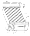
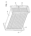
- Figures 2 and 3 are front and rear a perspective showings respectively of the heat exchangers of the furnace of Figure 1 .
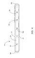
- Figure 4 is a cross sectional showing of one heat exchanger shown in Figure 3 .
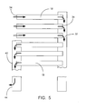
- Figure 5 is a schematic representation of the travel of the combustion gases through the heat exchangers of Figure 4 .
- the present invention provides a novel heat exchanger construction which may be used preferably as a secondary heat exchanger. While in the present illustrative embodiment, the novel heat exchangers are shown as secondary heat exchangers, it is contemplated that they also may be employed in certain situations as primary heat exchangers.
- Furnace 10 includes a pair of spaced apart supporting walls 12 and 14 which support therebetween primary heat exchangers 16 and secondary heat exchangers 18.
- Each of the primary and secondary heat exchangers are formed of a heat conducting metal, preferably aluminum.
- the primary heat exchangers 16 may be of the type shown and described in commonly owned EP-A-1318362 entitled “Compact High Efficiency Claim Shell Heat Exchanger". The disclosure in this application is incorporated herein for all purposes.
- Primary heat exchangers 16 may be aligned in vertically spaced succession and may be of the clam shell variety having an inlet port 16a at wall 12, a serpentine passageway 17, and an exhaust port 16b at the other end of the serpentine passageway 17 opening to wall 12. Combustion gases from a burner (not shown) enter the primary heat exchanger 16 through port 16a travel through the serpentine passageway 17 and exit exhaust ports 16b.
- secondary heat exchangers 18 are employed. Secondary heat exchangers 18 are designed to take the exhaust exiting outlet ports 16b and move the gases through the secondary heat exchangers so that the heat from the exhaust can be employed.
- a fan (not shown) may be supported by the furnace 10 to move air across the primary and secondary heat exchangers to provide warm air to the space to be heated.
- the wall 12 of furnace 10 supports an exhaust chamber 20 which is disposed over the exhaust ports 16b and the ends of the secondary heat exchanger 18 to direct exhaust gases from the primary heat exchangers through the secondary heat exchangers in a manner which will be described in further detail hereinbelow.
- a fan or other similar device may be used to draw the exhaust gas through the primary and secondary heat exchangers.
- Each secondary heat exchanger 18 is an elongate integrally formed heat conductive metal member having a plurality of aligned channels therethrough.
- each heat exchanger 18 includes a top wall 22, a bottom wall 24 and a plurality of integrally formed dividing walls 26 forming individual elongate channels 25.
- the number of such channels may be selected based upon space and heat efficiency needs.
- the centrally located walls 26a are generally planar and parallel to one another while the end walls 26b may include a curved configuration.
- the walls 26 divide the heat exchanger into smaller parallel channels which result in higher heat transfer efficiency while maintaining a compact overall configuration.
- Such an arrangement assures more wall contact between the surface of the heat exchanger and the gases passing therethrough.
- the open area of the secondary heat exchanger is significantly less than the open area of the primary area heater and there is a relatively large pressure drop loss as the gases flow through the secondary heat exchanger tubes.
- the flow resistance through the secondary tubes causes a "balanced" flow through the tube.
- the gases "look" for the flow path of least resistance thus balancing the flow. Maintaining a high flow velocity significantly improves heat transfer. By increasing the number of passes without any increase in the size of the heat exchanger heat transfer is improved.
- a plurality of such heat exchangers are arranged in a vertically stacked arrangement between support elements 30 and 32 supporting opposite ends of the heat exchangers 18.
- the support members are in turn supported by walls 12 and 14 of furnace 10 ( Figure 1 ).
- Each of the heat exchangers 18 is preferably formed of identical construction.
- the ends of the channels supported by the support members define ports 34 which provide for inlet or outlet of exhaust gases flowing within the channels 25.
- the channels 25, being bounded by top and bottom walls 22 and 24, and dividing walls 26, effectively transfer the heat of the exhaust gases flowing therethrough to the walls. Also, by increasing the number of walls in contact with the exhaust gases, additional heat transfer to the surface of the heat exchanger is provided. Due to the compact size of the heat exchanger 18 and the effective transfer of heat to the walls thereof, an over all increase in heat transfer efficiency is achieved.
- the heat exchangers 18 are supported between support elements 30 and 32.
- Support element 30 supports one end of the heat exchangers with the ports 34 at that end being exteriorly accessible through the wall of the support 30.
- An exhaust gas chamber 40 is positioned on support wall 30 so as to overlie the ports of all but the upper three of the heat exchangers.
- the chamber has an interior 42 which is in fluid communication with the ports of the covered heat exchangers.
- the chamber 40 includes a lower exhaust opening 44 which will be described in further detail herein below.
- support element 32 individually accommodates each end of all of the heat exchangers and defines a fluid chamber, the interior 33 of which is in communication with each of the ends of the heat exchanger ports supported therein.
- chamber 40 as well as the chamber defined by support 32 are in fluid communication through the heat exchangers supported therebetween.
- exhaust chamber 20 is positioned to overlie exhaust ports 16b as well as support 30 and the chamber 40 positioned thereover. Exhaust chamber 20 places each of the exhaust ports 16b and the heat exchanger ports 34 which are not covered by chamber 40, in fluid communication. Exhaust chamber 20 includes an exhaust opening 22 aligned with opening 44 of chamber 40. The exhaust chamber 20 allows exhaust gas exiting through ports 16b to be received within the ports 34 of the exposed heat exchangers 18 so that the exhaust gases traveling through heat exchangers 16 may be recaptured and used through secondary heat exchangers 18. This allows the furnace 10 of the present invention to extract additional energy from the flue gas exiting the primary heat exchangers 16.
- the flow of the exhaust gases through the secondary heat exchanger is shown schematically in Figure 5 .
- the exhaust gases which exit ports 16b ( Figure 1 ) from the primary heat exchangers 16 are directed to ports 34 of the upper three of the secondary heat exchangers 18.
- a fan maybe used to directionally pull the exhaust gases.
- the exhaust gases travel through the individual channels 25 ( Figure 4 ) of heat exchangers 18 transferring the heat of the exhaust gases to the walls of the secondary heat exchangers 18.
- the exhaust gases exit the opposite end of the heat exchangers 18 through ports 34 and are directed towards the next three heat exchangers immediately below.
- the exhaust gases thereupon enter ports 34 supported within support member 32 and travel along channels 25 again heating the walls therebetween. This travel of the exhaust gases continues in a serpentine fashion until finally the exhaust gases exit opening 44 in chamber 40 and are vented.
- the present invention employs the exhaust gas exiting primary heat exchangers 16 to heat the secondary heat exchangers 18 to extract additional heat from the exhaust gas. Moreover, as the secondary heat exchangers place the exhaust gases in direct contact with multiple wall surfaces of the heat exchangers 18, the heat from the exhaust gas which would normally be directly vented may be efficiently employed in the furnace 10.
Landscapes
- Engineering & Computer Science (AREA)
- Physics & Mathematics (AREA)
- Thermal Sciences (AREA)
- Mechanical Engineering (AREA)
- General Engineering & Computer Science (AREA)
- Geometry (AREA)
- Heat-Exchange Devices With Radiators And Conduit Assemblies (AREA)
- Incineration Of Waste (AREA)
Applications Claiming Priority (1)
| Application Number | Priority Date | Filing Date | Title |
|---|---|---|---|
| US90276307P | 2007-02-22 | 2007-02-22 |
Publications (2)
| Publication Number | Publication Date |
|---|---|
| EP1962043A1 true EP1962043A1 (fr) | 2008-08-27 |
| EP1962043B1 EP1962043B1 (fr) | 2011-12-28 |
Family
ID=39339740
Family Applications (1)
| Application Number | Title | Priority Date | Filing Date |
|---|---|---|---|
| EP08250162A Not-in-force EP1962043B1 (fr) | 2007-02-22 | 2008-01-14 | Échangeur thermique multi-canal |
Country Status (4)
| Country | Link |
|---|---|
| US (1) | US8113269B2 (fr) |
| EP (1) | EP1962043B1 (fr) |
| AT (1) | ATE539309T1 (fr) |
| CA (1) | CA2617763C (fr) |
Cited By (1)
| Publication number | Priority date | Publication date | Assignee | Title |
|---|---|---|---|---|
| WO2018160275A1 (fr) * | 2017-02-28 | 2018-09-07 | General Electric Company | Échangeur thermique fabriqué par addition comprenant des turbulateurs de flux définissant des passages de fluide internes |
Families Citing this family (8)
| Publication number | Priority date | Publication date | Assignee | Title |
|---|---|---|---|---|
| US7874156B2 (en) * | 2007-03-29 | 2011-01-25 | General Electric Company | Methods and apparatus for heating a fluid |
| US20100243228A1 (en) * | 2009-03-31 | 2010-09-30 | Price Richard J | Method and Apparatus to Effect Heat Transfer |
| US8721981B2 (en) * | 2009-11-30 | 2014-05-13 | General Electric Company | Spiral recuperative heat exchanging system |
| WO2015004720A1 (fr) * | 2013-07-08 | 2015-01-15 | 三菱電機株式会社 | Échangeur de chaleur, et appareil de conditionnement de l'air |
| CN107816897B (zh) * | 2017-11-02 | 2019-04-23 | 日照明祥铸造股份有限公司 | 一种节能式炼铁炉预热装置 |
| CN111473517B (zh) * | 2020-04-16 | 2022-04-15 | 吉林市安瑞克能源科技开发有限公司 | 一种可调管束式换热器、烘干塔换热调节系统及方法 |
| CN114440665A (zh) * | 2022-01-04 | 2022-05-06 | 广州迪森家居环境技术有限公司 | 热交换器及燃气采暖热水器 |
| CN115615216A (zh) * | 2022-10-18 | 2023-01-17 | 湛江双流主热交换器制造有限公司 | 一种提高壁挂炉热效能的主热交换装置 |
Citations (6)
| Publication number | Priority date | Publication date | Assignee | Title |
|---|---|---|---|---|
| EP0479388A1 (fr) * | 1990-10-03 | 1992-04-08 | Gastec N.V. | Réchauffeur d'air compact à gaz |
| US20030010480A1 (en) | 2001-07-16 | 2003-01-16 | Kazuhiro Shibagaki | Exhaust gas heat exchanger |
| EP1318362A2 (fr) | 2001-12-05 | 2003-06-11 | Thomas & Betts International, Inc. | Echangeur de chaleur à plaques compact et à haut rendement |
| US20050092316A1 (en) | 2003-11-04 | 2005-05-05 | Schonberger Marty L.Sr. | Hot air furnace |
| FR2870590A1 (fr) * | 2004-05-18 | 2005-11-25 | Valeo Thermique Moteur Sas | Echangeur de chaleur pour gaz d'echappement recircules de moteur a combustion interne |
| WO2007137863A1 (fr) * | 2006-06-01 | 2007-12-06 | Behr Gmbh & Co. Kg | Échangeur de chaleur |
Family Cites Families (38)
| Publication number | Priority date | Publication date | Assignee | Title |
|---|---|---|---|---|
| US1135840A (en) * | 1913-09-29 | 1915-04-13 | Universelle Des App Controleurs Soc | Gas-burner. |
| US1328589A (en) * | 1917-10-20 | 1920-01-20 | Roberts & Mander Stove Company | Oven-burner for gas-ranges |
| US1294999A (en) * | 1918-08-29 | 1919-02-18 | David Brickman | Gas-burner. |
| US2151540A (en) * | 1935-06-19 | 1939-03-21 | Varga Alexander | Heat exchanger and method of making same |
| US2096272A (en) * | 1935-07-15 | 1937-10-19 | Young Radiator Co | Turbulence means for radiator tubes |
| US2626656A (en) * | 1947-04-16 | 1953-01-27 | De Witt H Wyatt | Gas burner and internal baffle for gas distribution |
| US2625992A (en) * | 1949-06-30 | 1953-01-20 | Vernon S Beck | Multiple group gas burners with independent fuel and secondary air supplies |
| US2611359A (en) * | 1950-03-27 | 1952-09-23 | Clifford A Scogin | Forced air flow unit air heating furnace |
| US2751900A (en) * | 1951-05-22 | 1956-06-26 | Modine Mfg Co | Combustion type heater |
| US2788848A (en) * | 1951-11-09 | 1957-04-16 | Selas Corp Of America | Mixing type gas burner |
| US3411716A (en) * | 1966-05-11 | 1968-11-19 | United States Steel Corp | Oxygen lance for steelmaking furnaces |
| US3451472A (en) * | 1967-08-02 | 1969-06-24 | Julian W Keck | Two-stage baffle for high pressure feedwater heaters |
| US3596495A (en) * | 1969-04-01 | 1971-08-03 | Modine Mfg Co | Heat transfer device and method of making |
| US3603384A (en) * | 1969-04-08 | 1971-09-07 | Modine Mfg Co | Expandable tube, and heat exchanger |
| US3935855A (en) * | 1971-05-24 | 1976-02-03 | N.V. Werktuigenfabrieke Mulder | Air heater, especially for connection to a central heating system |
| DE2354502A1 (de) | 1973-10-31 | 1975-05-15 | Bosch Gmbh Robert | Oel- oder gasbeheizter wassererhitzer |
| US4106559A (en) * | 1976-12-29 | 1978-08-15 | Westinghouse Electric Corp. | Tube side flow control device for moisture separator reheaters |
| US4467780A (en) * | 1977-08-29 | 1984-08-28 | Carrier Corporation | High efficiency clamshell heat exchanger |
| US4300481A (en) * | 1979-12-12 | 1981-11-17 | General Electric Company | Shell and tube moisture separator reheater with outlet orificing |
| US4860725A (en) * | 1983-08-24 | 1989-08-29 | Yukon Energy Corporation | Power burner-fluid condensing mode furnace |
| JPH0674927B2 (ja) | 1985-04-08 | 1994-09-21 | 大阪瓦斯株式会社 | 天井吊下げ型遠赤外線暖房器 |
| US4738307A (en) * | 1985-09-20 | 1988-04-19 | Carrier Corporation | Heat exchanger for condensing furnace |
| US4825941B1 (en) * | 1986-07-29 | 1997-07-01 | Showa Aluminum Corp | Condenser for use in a car cooling system |
| DE3730117C1 (de) * | 1987-09-08 | 1988-06-01 | Norsk Hydro As | Verfahren zum Herstellen eines Waermetauschers,insbesondere eines Kraftfahrzeugkuehlers und Rohrprofil zur Verwendung bei einem derartigen Verfahren |
| US4945890A (en) * | 1989-09-05 | 1990-08-07 | Carrier Corporation | Induced draft warm air furnace with radiant infrared burner |
| US5094224A (en) * | 1991-02-26 | 1992-03-10 | Inter-City Products Corporation (Usa) | Enhanced tubular heat exchanger |
| US5178124A (en) * | 1991-08-12 | 1993-01-12 | Rheem Manufacturing Company | Plastic secondary heat exchanger apparatus for a high efficiency condensing furnace |
| US5186246A (en) * | 1992-06-01 | 1993-02-16 | General Motors Corporation | Extruded coolant/refrigerant tank with separate headers |
| JPH06249415A (ja) | 1993-02-25 | 1994-09-06 | Tokyo Gas Co Ltd | 窒素酸化物低発生バーナ |
| JPH06300473A (ja) * | 1993-04-19 | 1994-10-28 | Sanden Corp | 偏平冷媒管 |
| US5375586A (en) * | 1993-08-11 | 1994-12-27 | Inter-City Products Corporation (Usa) | Condensate isolator and drainage system for furnace |
| US5437263A (en) * | 1993-08-27 | 1995-08-01 | Goodman Manufacturing Company | High efficiency furnace method and apparatus |
| US5346002A (en) * | 1993-09-09 | 1994-09-13 | Carrier Corporation | Cell panel with extruded burner target plates and process for making same |
| US5555930A (en) * | 1994-06-24 | 1996-09-17 | Behr Heat Transfer, Inc. | Heat exchanger assembly with structural side passageways |
| WO1997024562A1 (fr) * | 1995-12-28 | 1997-07-10 | H-Tech, Inc. | Element chauffant pour fluides |
| US6889686B2 (en) * | 2001-12-05 | 2005-05-10 | Thomas & Betts International, Inc. | One shot heat exchanger burner |
| US6793012B2 (en) * | 2002-05-07 | 2004-09-21 | Valeo, Inc | Heat exchanger |
| KR100518856B1 (ko) * | 2003-09-04 | 2005-09-30 | 엘지전자 주식회사 | 플랫 튜브 열 교환기 |
-
2008
- 2008-01-09 US US12/008,135 patent/US8113269B2/en active Active
- 2008-01-11 CA CA2617763A patent/CA2617763C/fr active Active
- 2008-01-14 EP EP08250162A patent/EP1962043B1/fr not_active Not-in-force
- 2008-01-14 AT AT08250162T patent/ATE539309T1/de active
Patent Citations (6)
| Publication number | Priority date | Publication date | Assignee | Title |
|---|---|---|---|---|
| EP0479388A1 (fr) * | 1990-10-03 | 1992-04-08 | Gastec N.V. | Réchauffeur d'air compact à gaz |
| US20030010480A1 (en) | 2001-07-16 | 2003-01-16 | Kazuhiro Shibagaki | Exhaust gas heat exchanger |
| EP1318362A2 (fr) | 2001-12-05 | 2003-06-11 | Thomas & Betts International, Inc. | Echangeur de chaleur à plaques compact et à haut rendement |
| US20050092316A1 (en) | 2003-11-04 | 2005-05-05 | Schonberger Marty L.Sr. | Hot air furnace |
| FR2870590A1 (fr) * | 2004-05-18 | 2005-11-25 | Valeo Thermique Moteur Sas | Echangeur de chaleur pour gaz d'echappement recircules de moteur a combustion interne |
| WO2007137863A1 (fr) * | 2006-06-01 | 2007-12-06 | Behr Gmbh & Co. Kg | Échangeur de chaleur |
Cited By (3)
| Publication number | Priority date | Publication date | Assignee | Title |
|---|---|---|---|---|
| WO2018160275A1 (fr) * | 2017-02-28 | 2018-09-07 | General Electric Company | Échangeur thermique fabriqué par addition comprenant des turbulateurs de flux définissant des passages de fluide internes |
| US10184728B2 (en) | 2017-02-28 | 2019-01-22 | General Electric Company | Additively manufactured heat exchanger including flow turbulators defining internal fluid passageways |
| US10434575B2 (en) | 2017-02-28 | 2019-10-08 | General Electric Company | Additively manufactured heat exchanger including flow turbulators defining internal fluid passageways |
Also Published As
| Publication number | Publication date |
|---|---|
| EP1962043B1 (fr) | 2011-12-28 |
| US20080202736A1 (en) | 2008-08-28 |
| ATE539309T1 (de) | 2012-01-15 |
| US8113269B2 (en) | 2012-02-14 |
| CA2617763C (fr) | 2012-11-27 |
| CA2617763A1 (fr) | 2008-08-22 |
Similar Documents
| Publication | Publication Date | Title |
|---|---|---|
| CA2617763C (fr) | Echangeur de chaleur multicanaux | |
| CA2128471C (fr) | Echangeur de chaleur | |
| EP1318362B1 (fr) | Echangeur de chaleur à plaques compact et à haut rendement | |
| EP2160560B1 (fr) | Echangeur de chaleur pour chaudière | |
| KR101422347B1 (ko) | 더미 관을 갖는 응축 열교환기 | |
| EP0957327A1 (fr) | Ensemble serpentin d'un échangeur de chaleur | |
| US10006662B2 (en) | Condensing heat exchanger fins with enhanced airflow | |
| CA2127923C (fr) | Chaudiere de combustion a recuperation de la chaleur et comportant un echangeur de chaleur compact | |
| CN104735988B (zh) | 热风烘炉 | |
| JP5731936B2 (ja) | 給湯器 | |
| GB9806306D0 (en) | Heating appliance | |
| CN102405392A (zh) | 热交换器和适用于热交换器的鳍片 | |
| CN113028646B (zh) | 热交换器以及温水装置 | |
| NL1007309C2 (nl) | Warmtewisselaar. | |
| US11747046B2 (en) | Heat exchanger for water heater | |
| EP3877705B1 (fr) | Échangeur thermique avec système d'évacuation de gaz | |
| EP2554031B1 (fr) | Procédé et dispositif de transport de chaleur | |
| RU2296270C1 (ru) | Воздухоподогреватель | |
| US8771475B1 (en) | Intertwined tube coil arrangement for a delayed coker heater | |
| RU2296269C1 (ru) | Воздухоподогреватель | |
| GB2307037A (en) | Heat exchanger baffle element | |
| CA2144493C (fr) | Article a revetement decoratif et protecteur multicouche simulant le laiton | |
| CA2922855C (fr) | Echangeur de chaleur a allumage indirect | |
| NZ270708A (en) | Condensing furnace with recuperative heat exchanger having exchanger tubes sized for providing a furnace that is relatively compact, quiet and with low flue and air pressure losses | |
| PL8826S2 (pl) | Wymiennik ciepla |
Legal Events
| Date | Code | Title | Description |
|---|---|---|---|
| PUAI | Public reference made under article 153(3) epc to a published international application that has entered the european phase |
Free format text: ORIGINAL CODE: 0009012 |
|
| AK | Designated contracting states |
Kind code of ref document: A1 Designated state(s): AT BE BG CH CY CZ DE DK EE ES FI FR GB GR HR HU IE IS IT LI LT LU LV MC MT NL NO PL PT RO SE SI SK TR |
|
| AX | Request for extension of the european patent |
Extension state: AL BA MK RS |
|
| 17P | Request for examination filed |
Effective date: 20090212 |
|
| 17Q | First examination report despatched |
Effective date: 20090316 |
|
| AKX | Designation fees paid |
Designated state(s): AT BE BG CH CY CZ DE DK EE ES FI FR GB GR HR HU IE IS IT LI LT LU LV MC MT NL NO PL PT RO SE SI SK TR |
|
| GRAP | Despatch of communication of intention to grant a patent |
Free format text: ORIGINAL CODE: EPIDOSNIGR1 |
|
| GRAS | Grant fee paid |
Free format text: ORIGINAL CODE: EPIDOSNIGR3 |
|
| GRAA | (expected) grant |
Free format text: ORIGINAL CODE: 0009210 |
|
| AK | Designated contracting states |
Kind code of ref document: B1 Designated state(s): AT BE BG CH CY CZ DE DK EE ES FI FR GB GR HR HU IE IS IT LI LT LU LV MC MT NL NO PL PT RO SE SI SK TR |
|
| REG | Reference to a national code |
Ref country code: GB Ref legal event code: FG4D |
|
| REG | Reference to a national code |
Ref country code: CH Ref legal event code: EP |
|
| REG | Reference to a national code |
Ref country code: AT Ref legal event code: REF Ref document number: 539309 Country of ref document: AT Kind code of ref document: T Effective date: 20120115 |
|
| REG | Reference to a national code |
Ref country code: IE Ref legal event code: FG4D |
|
| REG | Reference to a national code |
Ref country code: NL Ref legal event code: T3 |
|
| REG | Reference to a national code |
Ref country code: DE Ref legal event code: R096 Ref document number: 602008012310 Country of ref document: DE Effective date: 20120308 |
|
| PG25 | Lapsed in a contracting state [announced via postgrant information from national office to epo] |
Ref country code: LT Free format text: LAPSE BECAUSE OF FAILURE TO SUBMIT A TRANSLATION OF THE DESCRIPTION OR TO PAY THE FEE WITHIN THE PRESCRIBED TIME-LIMIT Effective date: 20111228 Ref country code: NO Free format text: LAPSE BECAUSE OF FAILURE TO SUBMIT A TRANSLATION OF THE DESCRIPTION OR TO PAY THE FEE WITHIN THE PRESCRIBED TIME-LIMIT Effective date: 20120328 |
|
| LTIE | Lt: invalidation of european patent or patent extension |
Effective date: 20111228 |
|
| PG25 | Lapsed in a contracting state [announced via postgrant information from national office to epo] |
Ref country code: GR Free format text: LAPSE BECAUSE OF FAILURE TO SUBMIT A TRANSLATION OF THE DESCRIPTION OR TO PAY THE FEE WITHIN THE PRESCRIBED TIME-LIMIT Effective date: 20120329 Ref country code: SI Free format text: LAPSE BECAUSE OF FAILURE TO SUBMIT A TRANSLATION OF THE DESCRIPTION OR TO PAY THE FEE WITHIN THE PRESCRIBED TIME-LIMIT Effective date: 20111228 Ref country code: LV Free format text: LAPSE BECAUSE OF FAILURE TO SUBMIT A TRANSLATION OF THE DESCRIPTION OR TO PAY THE FEE WITHIN THE PRESCRIBED TIME-LIMIT Effective date: 20111228 Ref country code: SE Free format text: LAPSE BECAUSE OF FAILURE TO SUBMIT A TRANSLATION OF THE DESCRIPTION OR TO PAY THE FEE WITHIN THE PRESCRIBED TIME-LIMIT Effective date: 20111228 Ref country code: HR Free format text: LAPSE BECAUSE OF FAILURE TO SUBMIT A TRANSLATION OF THE DESCRIPTION OR TO PAY THE FEE WITHIN THE PRESCRIBED TIME-LIMIT Effective date: 20111228 |
|
| PG25 | Lapsed in a contracting state [announced via postgrant information from national office to epo] |
Ref country code: CY Free format text: LAPSE BECAUSE OF FAILURE TO SUBMIT A TRANSLATION OF THE DESCRIPTION OR TO PAY THE FEE WITHIN THE PRESCRIBED TIME-LIMIT Effective date: 20111228 |
|
| PG25 | Lapsed in a contracting state [announced via postgrant information from national office to epo] |
Ref country code: EE Free format text: LAPSE BECAUSE OF FAILURE TO SUBMIT A TRANSLATION OF THE DESCRIPTION OR TO PAY THE FEE WITHIN THE PRESCRIBED TIME-LIMIT Effective date: 20111228 Ref country code: CZ Free format text: LAPSE BECAUSE OF FAILURE TO SUBMIT A TRANSLATION OF THE DESCRIPTION OR TO PAY THE FEE WITHIN THE PRESCRIBED TIME-LIMIT Effective date: 20111228 Ref country code: BG Free format text: LAPSE BECAUSE OF FAILURE TO SUBMIT A TRANSLATION OF THE DESCRIPTION OR TO PAY THE FEE WITHIN THE PRESCRIBED TIME-LIMIT Effective date: 20120328 Ref country code: IS Free format text: LAPSE BECAUSE OF FAILURE TO SUBMIT A TRANSLATION OF THE DESCRIPTION OR TO PAY THE FEE WITHIN THE PRESCRIBED TIME-LIMIT Effective date: 20120428 Ref country code: SK Free format text: LAPSE BECAUSE OF FAILURE TO SUBMIT A TRANSLATION OF THE DESCRIPTION OR TO PAY THE FEE WITHIN THE PRESCRIBED TIME-LIMIT Effective date: 20111228 |
|
| PG25 | Lapsed in a contracting state [announced via postgrant information from national office to epo] |
Ref country code: MC Free format text: LAPSE BECAUSE OF NON-PAYMENT OF DUE FEES Effective date: 20120131 Ref country code: PT Free format text: LAPSE BECAUSE OF FAILURE TO SUBMIT A TRANSLATION OF THE DESCRIPTION OR TO PAY THE FEE WITHIN THE PRESCRIBED TIME-LIMIT Effective date: 20120430 Ref country code: PL Free format text: LAPSE BECAUSE OF FAILURE TO SUBMIT A TRANSLATION OF THE DESCRIPTION OR TO PAY THE FEE WITHIN THE PRESCRIBED TIME-LIMIT Effective date: 20111228 Ref country code: RO Free format text: LAPSE BECAUSE OF FAILURE TO SUBMIT A TRANSLATION OF THE DESCRIPTION OR TO PAY THE FEE WITHIN THE PRESCRIBED TIME-LIMIT Effective date: 20111228 |
|
| REG | Reference to a national code |
Ref country code: CH Ref legal event code: PL |
|
| REG | Reference to a national code |
Ref country code: AT Ref legal event code: MK05 Ref document number: 539309 Country of ref document: AT Kind code of ref document: T Effective date: 20111228 |
|
| REG | Reference to a national code |
Ref country code: IE Ref legal event code: MM4A |
|
| PG25 | Lapsed in a contracting state [announced via postgrant information from national office to epo] |
Ref country code: LI Free format text: LAPSE BECAUSE OF NON-PAYMENT OF DUE FEES Effective date: 20120131 Ref country code: DK Free format text: LAPSE BECAUSE OF FAILURE TO SUBMIT A TRANSLATION OF THE DESCRIPTION OR TO PAY THE FEE WITHIN THE PRESCRIBED TIME-LIMIT Effective date: 20111228 Ref country code: CH Free format text: LAPSE BECAUSE OF NON-PAYMENT OF DUE FEES Effective date: 20120131 |
|
| PLBE | No opposition filed within time limit |
Free format text: ORIGINAL CODE: 0009261 |
|
| STAA | Information on the status of an ep patent application or granted ep patent |
Free format text: STATUS: NO OPPOSITION FILED WITHIN TIME LIMIT |
|
| 26N | No opposition filed |
Effective date: 20121001 |
|
| REG | Reference to a national code |
Ref country code: DE Ref legal event code: R097 Ref document number: 602008012310 Country of ref document: DE Effective date: 20121001 |
|
| PG25 | Lapsed in a contracting state [announced via postgrant information from national office to epo] |
Ref country code: IE Free format text: LAPSE BECAUSE OF NON-PAYMENT OF DUE FEES Effective date: 20120114 Ref country code: AT Free format text: LAPSE BECAUSE OF FAILURE TO SUBMIT A TRANSLATION OF THE DESCRIPTION OR TO PAY THE FEE WITHIN THE PRESCRIBED TIME-LIMIT Effective date: 20111228 |
|
| PG25 | Lapsed in a contracting state [announced via postgrant information from national office to epo] |
Ref country code: ES Free format text: LAPSE BECAUSE OF FAILURE TO SUBMIT A TRANSLATION OF THE DESCRIPTION OR TO PAY THE FEE WITHIN THE PRESCRIBED TIME-LIMIT Effective date: 20120408 |
|
| PG25 | Lapsed in a contracting state [announced via postgrant information from national office to epo] |
Ref country code: FI Free format text: LAPSE BECAUSE OF FAILURE TO SUBMIT A TRANSLATION OF THE DESCRIPTION OR TO PAY THE FEE WITHIN THE PRESCRIBED TIME-LIMIT Effective date: 20111228 |
|
| PG25 | Lapsed in a contracting state [announced via postgrant information from national office to epo] |
Ref country code: MT Free format text: LAPSE BECAUSE OF FAILURE TO SUBMIT A TRANSLATION OF THE DESCRIPTION OR TO PAY THE FEE WITHIN THE PRESCRIBED TIME-LIMIT Effective date: 20111228 |
|
| REG | Reference to a national code |
Ref country code: GB Ref legal event code: 732E Free format text: REGISTERED BETWEEN 20140320 AND 20140326 |
|
| PG25 | Lapsed in a contracting state [announced via postgrant information from national office to epo] |
Ref country code: TR Free format text: LAPSE BECAUSE OF FAILURE TO SUBMIT A TRANSLATION OF THE DESCRIPTION OR TO PAY THE FEE WITHIN THE PRESCRIBED TIME-LIMIT Effective date: 20111228 |
|
| REG | Reference to a national code |
Ref country code: DE Ref legal event code: R082 Ref document number: 602008012310 Country of ref document: DE Representative=s name: BOEHMERT & BOEHMERT, DE |
|
| PG25 | Lapsed in a contracting state [announced via postgrant information from national office to epo] |
Ref country code: LU Free format text: LAPSE BECAUSE OF NON-PAYMENT OF DUE FEES Effective date: 20120114 |
|
| REG | Reference to a national code |
Ref country code: DE Ref legal event code: R082 Ref document number: 602008012310 Country of ref document: DE Representative=s name: BOEHMERT & BOEHMERT, DE Effective date: 20140506 Ref country code: DE Ref legal event code: R081 Ref document number: 602008012310 Country of ref document: DE Owner name: REZNOR MANUFACTURING COMPANY, LLC (N.D.GES.D. , US Free format text: FORMER OWNER: THOMAS & BETTS INTERNATIONAL, INC., WILMINGTON, US Effective date: 20120124 Ref country code: DE Ref legal event code: R081 Ref document number: 602008012310 Country of ref document: DE Owner name: REZNOR MANUFACTURING COMPANY, LLC (N.D.GES.D. , US Free format text: FORMER OWNER: THOMAS & BETTS INTERNATIONAL, INC., WILMINGTON, US Effective date: 20140506 Ref country code: DE Ref legal event code: R081 Ref document number: 602008012310 Country of ref document: DE Owner name: REZNOR MANUFACTURING COMPANY, LLC (N.D.GES.D. , US Free format text: FORMER OWNER: THOMAS & BETTS INTERNATIONAL, INC., WILMINGTON, DEL., US Effective date: 20140506 Ref country code: DE Ref legal event code: R082 Ref document number: 602008012310 Country of ref document: DE Representative=s name: BOEHMERT & BOEHMERT ANWALTSPARTNERSCHAFT MBB -, DE Effective date: 20140506 Ref country code: DE Ref legal event code: R081 Ref document number: 602008012310 Country of ref document: DE Owner name: REZNOR MANUFACTURING COMPANY, LLC (N.D.GES.D. , US Free format text: FORMER OWNER: THOMAS & BETTS INTERNATIONAL, INC., WILMINGTON, DELAWARE, US Effective date: 20120124 |
|
| REG | Reference to a national code |
Ref country code: FR Ref legal event code: TP Owner name: REZNOR MANUFACTURING COMPANY, LLC, US Effective date: 20140610 |
|
| PG25 | Lapsed in a contracting state [announced via postgrant information from national office to epo] |
Ref country code: HU Free format text: LAPSE BECAUSE OF FAILURE TO SUBMIT A TRANSLATION OF THE DESCRIPTION OR TO PAY THE FEE WITHIN THE PRESCRIBED TIME-LIMIT Effective date: 20080114 |
|
| REG | Reference to a national code |
Ref country code: NL Ref legal event code: SD Effective date: 20150210 |
|
| REG | Reference to a national code |
Ref country code: FR Ref legal event code: PLFP Year of fee payment: 9 |
|
| PGFP | Annual fee paid to national office [announced via postgrant information from national office to epo] |
Ref country code: IT Payment date: 20160122 Year of fee payment: 9 Ref country code: DE Payment date: 20160127 Year of fee payment: 9 |
|
| PGFP | Annual fee paid to national office [announced via postgrant information from national office to epo] |
Ref country code: FR Payment date: 20160126 Year of fee payment: 9 |
|
| PGFP | Annual fee paid to national office [announced via postgrant information from national office to epo] |
Ref country code: NL Payment date: 20170126 Year of fee payment: 10 |
|
| PGFP | Annual fee paid to national office [announced via postgrant information from national office to epo] |
Ref country code: GB Payment date: 20170127 Year of fee payment: 10 Ref country code: BE Payment date: 20170127 Year of fee payment: 10 |
|
| REG | Reference to a national code |
Ref country code: DE Ref legal event code: R119 Ref document number: 602008012310 Country of ref document: DE |
|
| REG | Reference to a national code |
Ref country code: FR Ref legal event code: ST Effective date: 20170929 |
|
| PG25 | Lapsed in a contracting state [announced via postgrant information from national office to epo] |
Ref country code: FR Free format text: LAPSE BECAUSE OF NON-PAYMENT OF DUE FEES Effective date: 20170131 |
|
| PG25 | Lapsed in a contracting state [announced via postgrant information from national office to epo] |
Ref country code: DE Free format text: LAPSE BECAUSE OF NON-PAYMENT OF DUE FEES Effective date: 20170801 |
|
| PG25 | Lapsed in a contracting state [announced via postgrant information from national office to epo] |
Ref country code: IT Free format text: LAPSE BECAUSE OF NON-PAYMENT OF DUE FEES Effective date: 20170114 |
|
| REG | Reference to a national code |
Ref country code: NL Ref legal event code: MM Effective date: 20180201 |
|
| GBPC | Gb: european patent ceased through non-payment of renewal fee |
Effective date: 20180114 |
|
| REG | Reference to a national code |
Ref country code: BE Ref legal event code: MM Effective date: 20180131 Ref country code: BE Ref legal event code: PD Owner name: REZNOR MANUFACTURING COMPANY, LLC; US Free format text: DETAILS ASSIGNMENT: CHANGE OF OWNER(S), AFFECTATION / CESSION; FORMER OWNER NAME: THOMAS & BETTS INTERNATIONAL, INC. Effective date: 20140925 |
|
| PG25 | Lapsed in a contracting state [announced via postgrant information from national office to epo] |
Ref country code: BE Free format text: LAPSE BECAUSE OF NON-PAYMENT OF DUE FEES Effective date: 20180131 Ref country code: NL Free format text: LAPSE BECAUSE OF NON-PAYMENT OF DUE FEES Effective date: 20180201 Ref country code: GB Free format text: LAPSE BECAUSE OF NON-PAYMENT OF DUE FEES Effective date: 20180114 |