EP1962285A1 - Datenseite mit erhöhter Datenkapazität - Google Patents
Datenseite mit erhöhter Datenkapazität Download PDFInfo
- Publication number
- EP1962285A1 EP1962285A1 EP07102791A EP07102791A EP1962285A1 EP 1962285 A1 EP1962285 A1 EP 1962285A1 EP 07102791 A EP07102791 A EP 07102791A EP 07102791 A EP07102791 A EP 07102791A EP 1962285 A1 EP1962285 A1 EP 1962285A1
- Authority
- EP
- European Patent Office
- Prior art keywords
- data
- pixels
- optical storage
- data page
- groups
- Prior art date
- Legal status (The legal status is an assumption and is not a legal conclusion. Google has not performed a legal analysis and makes no representation as to the accuracy of the status listed.)
- Withdrawn
Links
- 230000003287 optical effect Effects 0.000 claims abstract description 71
- 238000000034 method Methods 0.000 claims abstract description 19
- 238000013500 data storage Methods 0.000 description 15
- 238000013459 approach Methods 0.000 description 3
- 230000001427 coherent effect Effects 0.000 description 2
- 238000005516 engineering process Methods 0.000 description 2
- 239000011159 matrix material Substances 0.000 description 2
- 238000012986 modification Methods 0.000 description 2
- 230000004048 modification Effects 0.000 description 2
- 238000004088 simulation Methods 0.000 description 2
- 241000854350 Enicospilus group Species 0.000 description 1
- 230000006978 adaptation Effects 0.000 description 1
- 230000000694 effects Effects 0.000 description 1
- 239000011232 storage material Substances 0.000 description 1
Images


Classifications
-
- G—PHYSICS
- G11—INFORMATION STORAGE
- G11B—INFORMATION STORAGE BASED ON RELATIVE MOVEMENT BETWEEN RECORD CARRIER AND TRANSDUCER
- G11B7/00—Recording or reproducing by optical means, e.g. recording using a thermal beam of optical radiation by modifying optical properties or the physical structure, reproducing using an optical beam at lower power by sensing optical properties; Record carriers therefor
- G11B7/004—Recording, reproducing or erasing methods; Read, write or erase circuits therefor
- G11B7/0065—Recording, reproducing or erasing by using optical interference patterns, e.g. holograms
-
- G—PHYSICS
- G11—INFORMATION STORAGE
- G11B—INFORMATION STORAGE BASED ON RELATIVE MOVEMENT BETWEEN RECORD CARRIER AND TRANSDUCER
- G11B7/00—Recording or reproducing by optical means, e.g. recording using a thermal beam of optical radiation by modifying optical properties or the physical structure, reproducing using an optical beam at lower power by sensing optical properties; Record carriers therefor
- G11B7/007—Arrangement of the information on the record carrier, e.g. form of tracks, actual track shape, e.g. wobbled, or cross-section, e.g. v-shaped; Sequential information structures, e.g. sectoring or header formats within a track
- G11B7/00772—Arrangement of the information on the record carrier, e.g. form of tracks, actual track shape, e.g. wobbled, or cross-section, e.g. v-shaped; Sequential information structures, e.g. sectoring or header formats within a track on record carriers storing information in the form of optical interference patterns, e.g. holograms
-
- G—PHYSICS
- G11—INFORMATION STORAGE
- G11B—INFORMATION STORAGE BASED ON RELATIVE MOVEMENT BETWEEN RECORD CARRIER AND TRANSDUCER
- G11B7/00—Recording or reproducing by optical means, e.g. recording using a thermal beam of optical radiation by modifying optical properties or the physical structure, reproducing using an optical beam at lower power by sensing optical properties; Record carriers therefor
- G11B7/24—Record carriers characterised by shape, structure or physical properties, or by the selection of the material
- G11B7/2407—Tracks or pits; Shape, structure or physical properties thereof
- G11B7/24085—Pits
Definitions
- the present invention relates to a data page for an optical storage system with an increased data capacity, to a modulation method and a method for recording such a data page, and to an apparatus for reading from and/or writing to optical storage media using such a modulation method or recording method.
- holographic data storage digital data are stored by recording the interference pattern produced by the superposition of two coherent laser beams, where one beam, the so-called 'object beam', is modulated by a spatial light modulator (SLM) and carries the information to be recorded.
- the second beam serves as a reference beam.
- the interference pattern leads to modifications of specific properties of the storage material, which depend on the local intensity of the interference pattern. Reading of a recorded hologram is performed by illuminating the hologram with the reference beam using the same conditions as during recording. This results in the reconstruction of the recorded object beam.
- holographic data storage is an increased data capacity. Contrary to conventional optical storage media, the volume of the holographic storage medium is used for storing information, not just a single or few 2-dimensional layers.
- One further advantage of holographic data storage is the possibility to store multiple data in the same volume, e.g. by changing the angle between the two beams or by using shift multiplexing, etc.
- data are stored as data pages.
- a data page consists of a matrix of light-dark-patterns, i.e. a two dimensional binary array or an array of grey values, which code multiple bits. This allows to achieve increased data rates in addition to the increased storage density.
- the data page is imprinted onto the object beam by the spatial light modulator (SLM) and detected with a detector array.
- SLM spatial light modulator
- the diffraction limit determines the minimum distance between two information units that can be distinguished.
- the smallest resolvable information units are symbols, i.e. groups of pixels of a data page.
- a symbol is obtained by grouping multiple pixels of the SLM.
- a block of 2 ⁇ 2 SLM pixels represents a single symbol of a data page.
- a 2-dimensional modulation scheme is applied for holographic data storage.
- the size of one symbol is designed to be greater or equal to the diffraction limit of the optical system.
- a common approach is to divide each data page into a set of sub pages or blocks.
- Each block consists of e.g. 4 ⁇ 4 or 5 ⁇ 5 channel bits.
- the user data is transformed into a set of blocks.
- three on-symbols in each 4 ⁇ 4 block leads to a capacity of approximately nine bits of user data per block.
- this object is achieved by a data page for an optical storage system, wherein data are arranged as an array of pixels, where each pixel has a size below the optical resolution of the optical storage system, and wherein data bits are represented by groups of pixels, where each group of pixels has a size equal to or greater than the optical resolution of the optical storage system, which is characterized in that the positions and/or the sizes of the groups of pixels are adjustable in steps of the pixel size.
- a corresponding modulation method for a data page for an optical storage system has the steps of:
- the data page according to the invention enables to increase the data capacity of the entire optical storage medium by increasing the amount of user data per data page.
- the data page is suitable of any page oriented storage system, it is especially useful for holographic data storage systems.
- the storage capacity is increased significantly without modification of the optical path by using a high resolution SLM and a high resolution detector.
- the electronic components like SLM and detector are available as high speed and high resolution devices, the higher data capacity per data page additionally leads to a higher data rate.
- the invention makes use of the fact that differences of positions or sizes of channel bits or groups of pixels can be written and detected more precisely than the resolution given by the minimum spot size corresponding to the diffraction limit of the optical system.
- the optical system is designed in such a way that always a group of SLM pixels, where the size of the group can be greater or equal to the diffraction limited minimum spot size, represents one channel bit.
- the data are coded in blocks using the positions of the groups of pixels within the blocks and/or the sizes of the groups of pixels.
- Information is stored by spatially shifting the groups in units of one pixel on the SLM, or by varying the size of the groups in units of one pixel. Because the minimum shift or size variation is smaller than the optical resolution, more information can be stored.
- For reading the detector needs to have a sufficiently high resolution to detect the small differences in the positions or sizes of the channel bits.
- This can be regarded as an adaptation of run-length limited (RLL) modulation to a page oriented data storage system.
- the minimum distance between two adjacent groups of pixels within a block is equal to or greater than the optical resolution of the optical storage system. In this way it is ensured that all groups of pixels within a block can be reliably detected.
- the invention has two important aspects. First, it introduces a numerically efficient realization of an RLL modulation below optical resolution. Second, it proposes a block wise RLL modulation with adjustable white rate.
- the white rate i.e. the percentage of one attribute (white symbols)
- the white rate is important parameter in holographic data storage.
- the white rate can easily be adjusted by setting the number of symbols (i.e. 2 ⁇ 2 SLM pixels) per block. As this number is the same for all blocks, also the white rate of the whole data page is adjusted in this way.
- the modulation method according to the invention is used for generating a data page, which is then recorded on the optical storage medium.
- a data page according to the invention is first read from the optical storage medium. Subsequently the positions and/or the sizes of groups of pixels within the data page are detected.
- An optical storage medium advantageously includes data in the form of a data page according to the invention.
- the data page is recorded as a hologram in a holographic storage layer.
- Holographic data storage systems generally use a spatial light modulator to produce data pages in an object beam, which are stored in a holographic storage medium via interference of the object beam and a reference beam. During reading the reference beam illuminates the hologram and reconstructs the object beam with the data page, which is detected via a matrix detector.
- the optical resolution of the entire system is determined by the optical system, consisting of lenses, mirrors, apertures, etc.
- the optical resolution determines the diffraction limited minimum distance of two illuminated points, e.g. two SLM pixels, which can be distinguished after being sent through the optical system.
- the SLM is designed such that the size of each SLM pixel (channel bit) corresponds to the above diffraction limit. In this way it is ensured that there is no information loss caused by the limited optical resolution.
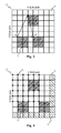
- a set 1 of SLM pixels 2 according to the invention is shown.
- the hatched area outlines the diffraction limited minimum spot size D.
- this spot is assumed to be rectangular. Of course, it can also be regarded as the envelope of the Airy disk resulting form a circular aperture.
- the rectangle consists of M ⁇ N pixels 2 and will be called a symbol in the following.
- the size of an SLM pixel 2 is explicitly chosen below the optical resolution.
- the number of combinations of three on-pixels (SLM pixel) in a 4 ⁇ 4 SLM pixel block (known as 4 ⁇ 4-3 modulation) is equal to the selection of 3 out of 16, i.e. the number of combinations equals 560. This corresponds to a capacity of ⁇ 9.1 bits of user data per pixel block.
- a block code with 2 ⁇ 2 SLM pixels for each symbol 3 corresponding to the optical resolution is illustrated in Fig. 2 .
- the black circles 4 indicate all possible positions of the upper left corner of a 2x2 symbol 3. Due to the diffraction limit not every combination out of this 18424 can be distinguished. Therefore, some constraints have to be introduced to determine the suitable combinations.
- the constraints are based on distances between the upper left corners of symbols 3.
- the distances may likewise be determined using any other point of the symbols 3, e.g. the center. Of course, it has to be ensured that the same point is chosen for all symbols 3. Defining the constraints based on the distances is not the only possibility. However, this approach can easily be implemented numerically. In Fig. 3 the definition of the distance measure is shown and some exemplary distances are indicated for three symbols p1, p2, p3.
- the distance of 9 between the two 2x2 symbols p2 and p3 is not allowed, as in this case the gap between the symbols is smaller than the optical resolution, which was assumed to be 2 ⁇ 2 SLM pixels.
- a minimum distance of 4 ensures non-overlapping sub-blocks.
- An example of a data page 6 with different sizes of channel bits is shown in Fig. 5 . In this case it is not necessary to arrange the channel bits in blocks as those shown in Fig 2 . and Fig. 3 . If the symbols are arranged in blocks, the block size will generally be larger than the 8 ⁇ 8 SLM pixels described above. Additional information on such 2-dimensional run-length limited modulation schemes can be found, for example, in Davey et al.: "Two-Dimensional Coding for a Multi-Track Recording System to combat Inter-Track Interference", IEEE Trans. Magn., VOL. 34 (1998), pp.
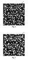
- FIG. 6 An example of a data page 6 with conventional block wise coding is illustrated in Fig. 6 .
- a typical 4 ⁇ 4-3 block modulation is shown, i.e. each block has 4 ⁇ 4 SLM pixels, of which three pixels are white pixels.
- the user data on this page is approximately 64*9.1 bits ⁇ 582 bits ⁇ 72 byte.
- the diffraction limited image of the SLM data page 6 of Fig. 6 on the detector is illustrated in Fig. 7 .
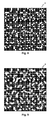
- FIG. 8 an exemplary SLM data page 6 is shown, where each single symbol is built by 2 ⁇ 2 SLM pixels.
- the constraints - no overlap of the white symbols - lead to approximately 64*13.53 bits ⁇ 865 bit ⁇ 108 byte of user data on this page.
- the diffraction limited image of the SLM data page 6 of Fig. 8 on the detector is illustrated in Fig. 9 .
- the diffraction limit was chosen as 2 ⁇ 2 SLM pixels. Simulations have proven that the original data can be demodulated.
- Fig. 10 depicts a further example of an SLM data page 6 using symbols consisting of 2 ⁇ 2 SLM pixels.
- the constraints - distance>10 and no direct neighbors within a block - lead to approximately 64*11.27 bits ⁇ 721 bits ⁇ 90 byte of user data.
- the diffraction limited image of the SLM data page 6 of Fig. 10 on the detector is shown in Fig. 11 . Also for this example simulations have proven that the original data can be demodulated.
- FIG. 12 an apparatus 7 for reading and/or recording a holographic storage medium 16 is shown schematically.
- a source of coherent light e.g. a laser diode 8 emits a light beam 9, which is collimated by a collimating lens 10.
- the light beam 9 is then divided into two separate light beams 13, 14.
- a spatial light modulator (SLM) 12 modulates one of the two beams, the so called "object beam” 13, to imprint a 2-dimensional data pattern.
- Both the object beam 13 and the further beam, the so called “reference beam” 14 are focused into a holographic storage medium 16, e.g. a holographic disk or card, by an objective lens 15.
- a holographic storage medium 16 e.g. a holographic disk or card
- the stored data are retrieved from the holographic storage medium 16 by illuminating a recorded hologram with the reference beam 14 only.
- the reference beam 14 is diffracted by the hologram structure and produces a copy of the original object beam 13, the reconstructed object beam 17.
- This reconstructed object beam 17 is collimated by the objective lens 9 and directed onto a 2-dimensional array detector 19, e.g. a CCD-array, by a second beam splitter 18.
- the array detector 19 allows to reconstruct the recorded data.
Landscapes
- Holo Graphy (AREA)
- Optical Recording Or Reproduction (AREA)
Priority Applications (1)
| Application Number | Priority Date | Filing Date | Title |
|---|---|---|---|
| EP07102791A EP1962285A1 (de) | 2007-02-21 | 2007-02-21 | Datenseite mit erhöhter Datenkapazität |
Applications Claiming Priority (1)
| Application Number | Priority Date | Filing Date | Title |
|---|---|---|---|
| EP07102791A EP1962285A1 (de) | 2007-02-21 | 2007-02-21 | Datenseite mit erhöhter Datenkapazität |
Publications (1)
| Publication Number | Publication Date |
|---|---|
| EP1962285A1 true EP1962285A1 (de) | 2008-08-27 |
Family
ID=38197738
Family Applications (1)
| Application Number | Title | Priority Date | Filing Date |
|---|---|---|---|
| EP07102791A Withdrawn EP1962285A1 (de) | 2007-02-21 | 2007-02-21 | Datenseite mit erhöhter Datenkapazität |
Country Status (1)
| Country | Link |
|---|---|
| EP (1) | EP1962285A1 (de) |
Cited By (1)
| Publication number | Priority date | Publication date | Assignee | Title |
|---|---|---|---|---|
| CN110060707A (zh) * | 2018-01-18 | 2019-07-26 | 青岛泰谷光电工程技术有限公司 | 一种光学讯号的编码方法和存取方法以及全像储存装置 |
Citations (4)
| Publication number | Priority date | Publication date | Assignee | Title |
|---|---|---|---|---|
| US6413680B1 (en) * | 1998-02-26 | 2002-07-02 | Kabushiki Kaisha Toyota Chuo Kenkyusho | Optical recording method, optical recording medium, and optical recording system |
| US20060050544A1 (en) * | 2002-10-09 | 2006-03-09 | Optware Corporation | Information recording method, reproducing method, and recording reproducing method utilizing holography |
| WO2006061777A2 (en) * | 2004-12-09 | 2006-06-15 | Koninklijke Philips Electronics N.V. | Read out of holographic optical storage media |
| EP1734516A1 (de) * | 2004-03-30 | 2006-12-20 | Pioneer Corporation | 2-dimensionales modulationsverfahren zum aufzeichnen eines hologramms und hologrammeinrichtung |
-
2007
- 2007-02-21 EP EP07102791A patent/EP1962285A1/de not_active Withdrawn
Patent Citations (4)
| Publication number | Priority date | Publication date | Assignee | Title |
|---|---|---|---|---|
| US6413680B1 (en) * | 1998-02-26 | 2002-07-02 | Kabushiki Kaisha Toyota Chuo Kenkyusho | Optical recording method, optical recording medium, and optical recording system |
| US20060050544A1 (en) * | 2002-10-09 | 2006-03-09 | Optware Corporation | Information recording method, reproducing method, and recording reproducing method utilizing holography |
| EP1734516A1 (de) * | 2004-03-30 | 2006-12-20 | Pioneer Corporation | 2-dimensionales modulationsverfahren zum aufzeichnen eines hologramms und hologrammeinrichtung |
| WO2006061777A2 (en) * | 2004-12-09 | 2006-06-15 | Koninklijke Philips Electronics N.V. | Read out of holographic optical storage media |
Cited By (1)
| Publication number | Priority date | Publication date | Assignee | Title |
|---|---|---|---|---|
| CN110060707A (zh) * | 2018-01-18 | 2019-07-26 | 青岛泰谷光电工程技术有限公司 | 一种光学讯号的编码方法和存取方法以及全像储存装置 |
Similar Documents
| Publication | Publication Date | Title |
|---|---|---|
| EP1734516B1 (de) | 2-dimensionales modulationsverfahren zum aufzeichnen eines hologramms und hologrammeinrichtung | |
| CN101373371B (zh) | 全息数据存储的相位掩模 | |
| JP4442162B2 (ja) | ホログラフィック記録再生システム | |
| JP5026331B2 (ja) | ホログラフィック記憶媒体からの読出しおよび/またはホログラフィック記憶媒体への書込みを行うための装置 | |
| EP1962285A1 (de) | Datenseite mit erhöhter Datenkapazität | |
| KR100999099B1 (ko) | 홀로그래피 광메모리 시스템에서의 데이터 기록 방법 | |
| CN100557688C (zh) | 光信息检测方法和光信息检测器 | |
| JP2022189643A (ja) | 変調符号作成方法およびホログラム記録再生装置 | |
| EP1808855B1 (de) | Intensitätsprofilkorrektur für Datenseiten für holografische Speicherung | |
| JP5122108B2 (ja) | ホログラフィック記憶媒体 | |
| EP2071566B1 (de) | Korrektur der Synchronisationsmarkierung für holografische Datenseiten | |
| JP2022061899A (ja) | 変調符号の生成方法およびホログラム記録再生装置 | |
| EP2063423A1 (de) | Verschiebungs-unempfindliche Speicherung von Informationen auf seitenorientierten optischen Datenspeichersystemen | |
| EP2015296A2 (de) | Holographisches Speichermedium mit integrierter Phasenmaske | |
| KR100551384B1 (ko) | 홀로그래픽 데이터 디코딩 방법 | |
| JP2010517203A (ja) | ホログラフィック記録媒体に/からデータを記録/再生する方法及びその装置 | |
| EP2273496A1 (de) | Verfahren zum Auffinden von Synchronisierungsmarkierungen | |
| YANG et al. | Department of Electrophysics |
Legal Events
| Date | Code | Title | Description |
|---|---|---|---|
| PUAI | Public reference made under article 153(3) epc to a published international application that has entered the european phase |
Free format text: ORIGINAL CODE: 0009012 |
|
| AK | Designated contracting states |
Kind code of ref document: A1 Designated state(s): AT BE BG CH CY CZ DE DK EE ES FI FR GB GR HU IE IS IT LI LT LU LV MC NL PL PT RO SE SI SK TR |
|
| AX | Request for extension of the european patent |
Extension state: AL BA HR MK RS |
|
| AKX | Designation fees paid | ||
| STAA | Information on the status of an ep patent application or granted ep patent |
Free format text: STATUS: THE APPLICATION IS DEEMED TO BE WITHDRAWN |
|
| 18D | Application deemed to be withdrawn |
Effective date: 20090228 |
|
| REG | Reference to a national code |
Ref country code: DE Ref legal event code: 8566 |