EP1962537B1 - Scheduling-verfahren, basisstation und endgerät - Google Patents
Scheduling-verfahren, basisstation und endgerät Download PDFInfo
- Publication number
- EP1962537B1 EP1962537B1 EP05816644A EP05816644A EP1962537B1 EP 1962537 B1 EP1962537 B1 EP 1962537B1 EP 05816644 A EP05816644 A EP 05816644A EP 05816644 A EP05816644 A EP 05816644A EP 1962537 B1 EP1962537 B1 EP 1962537B1
- Authority
- EP
- European Patent Office
- Prior art keywords
- pilot
- terminal
- signal
- base station
- scheduling
- Prior art date
- Legal status (The legal status is an assumption and is not a legal conclusion. Google has not performed a legal analysis and makes no representation as to the accuracy of the status listed.)
- Ceased
Links
Images


Classifications
-
- H—ELECTRICITY
- H04—ELECTRIC COMMUNICATION TECHNIQUE
- H04W—WIRELESS COMMUNICATION NETWORKS
- H04W72/00—Local resource management
- H04W72/20—Control channels or signalling for resource management
- H04W72/23—Control channels or signalling for resource management in the downlink direction of a wireless link, i.e. towards a terminal
-
- H—ELECTRICITY
- H04—ELECTRIC COMMUNICATION TECHNIQUE
- H04W—WIRELESS COMMUNICATION NETWORKS
- H04W72/00—Local resource management
- H04W72/12—Wireless traffic scheduling
- H04W72/1263—Mapping of traffic onto schedule, e.g. scheduled allocation or multiplexing of flows
- H04W72/1268—Mapping of traffic onto schedule, e.g. scheduled allocation or multiplexing of flows of uplink data flows
Definitions
- the present invention relates to a radio communications system including at least one base station and at least one terminal that is present in a service area covered by the base station. More particularly, the present invention relates to a pilot-signal scheduling method in the communications system.
- Non-patent document 1 discloses a technology to achieve the purpose.
- a base station specifies "UE pointer” indicative of a maximum transmission power (i.e., highest data-transmission rate) available for a terminal.
- TFC Transport Format Combination
- TFC0 to TFC10 transmission power set by the "UE pointer”.
- the "UE pointer” is specified by "Scheduling Grant” disclosed in Non-patent document 2.
- Information about allocation that is prespecified by the "Scheduling Grant” indicates the unique and highest transmission power.
- the information includes a unique ID of each terminal. Therefore, the terminal can determine whether "Scheduling Grant" is addressed thereto by detecting the ID.
- a plurality of terminals can transmit data at the same time.
- Time Scheduling disclosed in Non-patent document 1 restricts terminal's transmission time instead of specifying terminal's transmission power. Although fewer than those allowed to simultaneously transmit data in "Rate Scheduling", this scheduling enables a plurality of terminals to transmit data at the same time. The above-described “Time Scheduling” is not used in the final standards.
- Evolved UTRA and UTRAN A radio access system that is different from conventional 3G systems is to be used in "Evolved UTRA and UTRAN”.
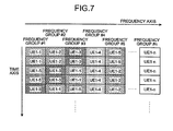
- uplink scheduling i.e., one of the technologies under study, allocates an available frequency and time to each of terminals (see, Fig. 7 ).
- quality of the uplink is required to be measured.
- the terminals transmit a known pattern (hereinafter, "pilot signal") to a base station.
- the present invention has been achieved to solve the above problems in the conventional technology and it is an object of the present invention to provide a scheduling method capable of preventing collisions between pilot signals or between a pilot signal and a data signal, and identifying a sender of a received pilot signal without using an extra unit.
- a pilot-signal scheduling method used in a radio communications system in which a base station measures reception quality based on a pilot signal received from a terminal in a service area of the base station.
- the pilot-signal scheduling method includes a scheduling step in which the base station generates scheduling information for specifying a time (including a start time and a cycle) for transmission of a pilot signal and a specific frequency band at which the pilot signal is to be transmitted such that transmissions of pilot signals from terminals in the service area will not overlap, and an information transmitting step in which the base station transmits the scheduling information by a predetermined transmitting process.
- a scheduling method makes it possible to prevent collisions between pilot signals and identify a sender of a received pilot signal without using an extra unit.
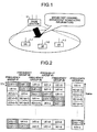
- Fig. 1 is a diagram for explaining the structure of a radio communications system that implements the scheduling method according to the present invention.
- terminals user equipment: UE
- UE user equipment
- the base station 11 notifies the user equipment 1-1 to 1-3 of pilot-signal scheduling information via a common channel (for example, a broadcast channel).
- a common channel for example, a broadcast channel.
- the scheduling information is broadcasted via the common channel, it is allowable to notify each user equipment of common scheduling information via an individual channel of the user equipment.
- Fig. 2 is a diagram for explaining the pilot-signal scheduling method according to the present embodiment. More specifically, pilot-signal transmission timing of each UE (1-1 to 1-n) (equivalent to later-described pilot-signal transmission position) is scheduled to avoid collisions.
- the 3GPP defines a unit of time called TTI (Transmission Time Interval) and another unit called Frame constituted of a plurality of TTIs.
- TTI Transmission Time Interval
- Frame constituted of a plurality of TTIs.
- frequency bandwidth that is prepared as a system band is divided into a plurality of groups.
- One frequency group can be made up from a single sub-channel, i.e., a unit of frequency, or a plurality of sub-channels.
- the UE 1-1 transmits a pilot signal at frequency group #1 in an initial time based on a later-described transition pattern that is based on the unit of time. After that, the UE 1-1 transmits a pilot signal, transiting to an adjacent frequency group each TTI after another.
- the UE 1-2 in contrast to the UE 1-1, transmits a pilot signal at frequency group #2 in the initial time. After that, the UE 1-2 transmits a pilot signal, transiting to an adjacent frequency group each TTI after another in a manner similar to the UE 1-1.
- the UE 1-3, the UE 1-4, ... transmits a pilot signal starting from a different position, transiting to an adjacent frequency group each TTI.
- the base station 11 specifies frequency group number, cycle and time of pilot-signal transmission from each UE.
- the base station 11 specifies these items of information by first notifying each UE of a transition pattern for a specific period (TTI-based frequency transition of the UE 1-1: #1, #2, ... #n, TTI-based frequency transition of the UE 1-2: #2, #3, ... #n, #1, ...), and then notifying each UE of another transition pattern for a next period.
- the base station 11 repeats notification of a different transition pattern for each period.
- the items of information need not be necessarily specified in the above manner. For example, the base station 11 can specify them by repeatedly notifying the same transition pattern every predetermined period.
- each UE transits to an adjacent frequency group at each TTI in the above example, it is allowable for UE to stay at the same frequency group over a plurality of TTIs, or to transit to not the adjacent frequency group but a spaced frequency group. It is also allowable to provide a time zone within which no pilot signal is to be transmitted from any UE. The time and the cycle about a pilot signal to be transmitted and a time zone within which no pilot signal is to be transmitted are specified by the base station.
- the base station 11 specifies time for switching to a next frequency, cycle, and target frequency group number with respect to a pilot signal to be transmitted from each UE. This makes it possible to prevent collisions between pilot signals. Moreover, because the base station 11 knows which timing each UE transmits a pilot signal, there is no need of a special unit for identifying a source UE of a pilot signal upon receipt of the pilot signal.
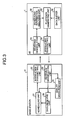
- Fig. 3 is a functional block diagram of the base station 11 and the UE 1 (equivalent to the UE 1-1 to 1-n described above).
- the base station 11 includes a scheduling unit 21, a modulating/transmitting unit 22, a receiving/demodulating unit 23, a quality measuring unit 24, and a data receiving unit 25;
- the UE 1 includes a receiving/demodulating unit 31, a scheduling-information analyzing unit 32, a pilot/data generating unit 33, a modulating/transmitting unit 34, and a data buffer unit 35.
- the scheduling unit 21 of the base station 11 performs scheduling about a pilot-signal transmission position (time for switching to a next frequency, cycle, and target frequency group number) and scheduling about the data-transmission position (time for switching to a next frequency, cycle, and target frequency group number).
- the base station 11 then notifies the UE 1 of the scheduling information via the modulating/transmitting unit 22.
- the receiving/demodulating unit 31 receives the scheduling information, and then the scheduling-information analyzing unit 32 determines the pilot-signal transmission position.
- the pilot-signal transmission position which is obtained as a result of the analysis, is sent to the pilot/data generating unit 33.
- the pilot/data generating unit 33 generates a pilot signal with a specified timing and a specified frequency band based on the received pilot-signal transmission position.
- the modulating/transmitting unit 34 transmits the generated pilot signal to the base station 11.
- the pilot/data generating unit 33 reads data from the data buffer unit 35, and transmits transmission data that is generated by adding necessary header information to the read data to the base station 11 via the modulating/transmitting unit 34.
- the receiving/demodulating unit 23 of the base station 11 receives signals from the UE 1.
- the quality measuring unit 24 measures reception quality from the pilot signal.
- the reception quality is measured by receiving-signal intensity, a ratio of a sum of interferential-wave power and thermal-noise power to a desired-wave power, or the like. After that, a result of the measurement is sent to the scheduling unit 21.
- the scheduling unit 21 performs communication-resource allocating process depending on whether the quality is improved or deteriorated.
- the data receiving unit 25 deletes the header information from the data, and sends the data without the header information to an upper layer.
- Fig. 4 is a diagram for explaining operation in the case that pilot-signal transmission timing of, for example, the UE 1-1 and 1-2 overlaps data-transmission timing of other UE.
- the frequency group #4 is allocated for transmission of data from the other UE.
- the UE 1-1 which is supposed to transmit a pilot signal at the frequency group #4, does not transmit a pilot signal at the timing because the UE 1-1 knows that the frequency group #4 is allocated for the transmission of data from the other UE.
- the UE 1-2 also does not transmits a pilot signal at the frequency group #4.
- each UE can easily obtain information on such transmission timing. Therefore, each UE can determine whether pilot-signal transmission timing thereof overlaps data-transmission timing of other UE with the scheduling-information analyzing unit 32. Thus, the UE can avoid collisions between a pilot signal transmitted therefrom and data transmitted from other UE.
- chunk which is a unit of scheduling defined by the TTI and the frequency group.
- Fig. 5 is a diagram for explaining an exemplary usage of the frequency groups (chunk).
- the single TTI is made up of a plurality of units called Block according to the study by the 3GPP.
- each UE UE 1-1, 1-k, 1-m, 1-p, and 1-x
- UE 1-1, 1-k, 1-m, 1-p, and 1-x is allocated to one of frequency sub-groups (any one of f1 group to f5 group), and a packet is transmitted with all Blocks making up the TTI.
- energy for receiving the pilot signal can be saved much, which makes it possible to improve accuracy in measuring the line quality.
- Fig. 6 is a diagram for explaining another exemplary chunk usage different from the usage shown in Fig. 5 .
- part of Blocks that constitutes the TTI is allocated for transmission of a pilot signal
- the remaining Blocks are allocated for transmission of data from one or a plurality of UE. Because a large part of the communication resource is allocated for transmission of data according to the method, it is possible to increase throughput of data transmission.
- the region allocated for transmission of data from other UE can be allocated for transmission of a pilot signal from other UE.
- the pilot-signal scheduling method according to the present invention is effectively used in a radio communications system, and particularly suitable for a radio communications system in which a base station measures reception quality based on a pilot signal received from a terminal in its coverage area and allocates radio resources based on a result of the measuring.
Landscapes
- Engineering & Computer Science (AREA)
- Computer Networks & Wireless Communication (AREA)
- Signal Processing (AREA)
- Mobile Radio Communication Systems (AREA)
Claims (14)
- Pilotsignal-Zeitplanungsverfahren, das auf ein Funkkommunikationssystem angewendet wird, in dem eine Basisstation eine Empfangsqualität auf Grundlage eines Pilotsignals misst, das von einem Endgerät in einem Versorgungsbereich der Basisstation her eingeht, wobei das Pilotsignal-Zeitplanungsverfahren an der Basisstation umfasst:Generieren von Zeitplanungsinformation, die die Pilotsignalübertragungszeit und ein Frequenzband genau festlegt, in der/dem jedes Endgerät ein Pilotsignal überträgt, so dass Übertragungen von Endgeräten in dem Versorgungsbereich sich nicht überschneiden, wobei die Pilotsignalübertragungszeit eine Zeit, zu der jedes Endgerät mit dem Übertragen von Pilotsignalen beginnt, und einen Zeitabschnitt umfasst, zu dem jedes Endgerät Pilotsignale überträgt; undÜbertragen der Zeitplanungsinformation an das Endgerät.
- Pilotsignal-Zeitplanungsverfahren nach Anspruch 1, wobei die Zeitplanungsinformation Information über einen Zeitbereich enthält, während dem jedes Endgerät kein Pilotsignal überträgt.
- Pilotsignal-Zeitplanungsverfahren nach Anspruch 1, wobei die Zeitplanungsinformation über einen gemeinsamen Kanal oder einen individuellen Kanal jedes Endgeräts an alle Endgeräte im Versorgungsbereich übertragen wird.
- Pilotsignal-Zeitplanungsverfahren nach Anspruch 1, wobei
Frequenzbänder mit einer vorbestimmten Bandbreite zu mehreren Frequenzgruppen zusammengefasst werden, und
das Generieren umfasst, eine der als Frequenzband festgelegten Frequenzgruppen in mehrere Teilgruppen zu unterteilen und jede der Teilgruppen zur Übertragung eines Pilotsignals von einem anderen Endgerät zuzuteilen. - Pilotsignal-Zeitplanungsverfahren nach Anspruch 1, wobei
Frequenzbänder mit einer vorbestimmten Bandbreite zu mehreren Frequenzgruppen zusammengefasst werden, und
das Generieren umfasst, eine der als Frequenzband festgelegten Frequenzgruppen in mehrere Teilgruppen zu unterteilen und einen Teil der Teilgruppen zur Pilotsignalübertragung zuzuteilen, und den übrigen Teil der Teilgruppen zur Datenübertragung zuzuteilen. - Pilotsignal-Zeitplanungsverfahren nach Anspruch 1, darüber hinaus am Endgerät umfassend:Analysieren der Zeitplanungsinformation; undÜbertragen eines Pilotsignals auf Grundlage der Pilotsignalübertragungszeit und des Frequenzbands, die/das durch die Zeitplanungsinformation festgelegt sind.
- Pilotsignal-Zeitplanungsverfahren nach Anspruch 6, wobei das Analysieren umfasst, zu bestimmen, wenn die Zeitplanungsinformation Information über eine Funkbetriebsmittelzuteilung zur Datenübertragung enthält, ob sich die Übertragung eines Pilotsignals von dem Endgerät mit einer Datenübertragung von einem anderen Endgerät überschneiden wird, wobei das Pilotsignal-Zeitplanungsverfahren darüber hinaus umfasst:kein Pilotsignal zu übertragen, wenn sich eine Übertragung des Pilotsignals mit einer Datenübertragung von einem anderen Endgerät überschneiden wird.
- Basisstation, die eine Zeitplanung von Pilotsignalen durchführt, die von einem Endgerät (1-1, 1-2, 1-3) in einem Versorgungsbereich der Basisstation (11) her eingehen, wobei die Basisstation (11) umfasst:eine Zeitplanungseinheit (21), die Zeitplanungsinformation generiert, die eine Pilotsignalübertragungszeit und ein Frequenzband festlegt, in der/dem jedes Endgerät (1-1, 1-2, 1-3) ein Pilotsignal überträgt, so dass sich Übertragungen von Endgeräten (1-1, 1-2, 1-3) in dem Versorgurigsbereich nicht überschneiden, wobei die Pilotsignalübertragungszeit eine Zeit umfasst, zu der jedes Endgerät (1-1, 1-2, 1-3) mit dem Übertragen von Pilotsignalen beginnt, und einen Zeitabschnitt umfasst, zu dem jedes Endgerät (1-1, 1-2, 1-3) Pilotsignale überträgt; undeine Übertragungseinheit (22), die die Zeitplanungsinformation an das Endgerät (1-1, 1-2, 1-3) überträgt.
- Basisstation nach Anspruch 8, wobei die Zeitplanungsinformation Information über einen Zeitbereich enthält, während dem jedes Endgerät (1-1, 1-2, 1-3) kein Pilotsignal überträgt.
- Basisstation nach Anspruch 8, wobei die Zeitplanungsinformation über einen gemeinsamen Kanal oder einen individuellen Kanal jedes Endgeräts an alle Endgeräte (1-1, 1-2, 1-3) im Versorgungsbereich übertragen wird.
- Basisstation nach Anspruch 8, wobei
Frequenzbänder mit einer vorbestimmten Bandbreite zu mehreren Frequenzgruppen zusammengefasst werden, und
die Zeitplanungseinheit (21) eine der als Frequenzband festgelegten Frequenzgruppen in mehrere Teilgruppen unterteilt und jede der Teilgruppen zur Übertragung eines Pilotsignals von einem anderen Endgerät (1-1, 1-2, 1-3) zuteilt. - Basisstation nach Anspruch 8, wobei
Frequenzbänder mit einer vorbestimmten Bandbreite zu mehreren Frequenzgruppen zusammengefasst werden, und
die Zeitplanungseinheit (21) eine der als Frequenzband festgelegten Frequenzgruppen in mehrere Teilgruppen unterteilt und einen Teil der Teilgruppen zur Pilotsignalübertragung zuteilt und den übrigen Teil der Teilgruppen zur Datenübertragung zuteilt. - Endgerät in einem Funkkommunikationssystem, das eine Basisstation (11) umfasst, die Zeitplanungsinformation generiert, die eine Pilotsignalübertragungszeit und ein Frequenzband festlegt, in der/dem jedes Endgerät (1-1, 1-2, 1-3) ein Pilotsignal überträgt, so dass sich Übertragungen von Endgeräten (1-1, 1-2, 1-3) in einem Versorgungsbereich der Basisstation (11) nicht überschneiden, wobei die Pilotsignalübertragungszeit eine Zeit, zu der jedes Endgerät (1-1, 1-2, 1-3) mit dem Übertragen von Pilotsignalen beginnt, und einen Zeitabschnitt umfasst, zu dem jedes Endgerät (1-1, 1-2, 1-3) Pilotsignale überträgt, und die die Zeitplanungsinformation an das Endgerät (1-1, 1-2, 1-3) überträgt, wobei das Endgerät (1-1, 1-2, 1-3), wenn es sich im Versorgungsbereich befindet, die Zeitplanungsinformation von der Basisstation (11) empfängt, wobei das Endgerät umfasst:eine Informationsanalysiereinheit (32), die die Zeitplanungsinformation analysiert; undeine Übertragungseinheit (34), die ein Pilotsignal auf Grundlage der Pilotsignalübertragungszeit und des Frequenzbands überträgt, die/das durch die Zeitplanungsinformation festgelegt sind.
- Endgerät nach Anspruch 13, wobei
die Analysiereinheit (32) bestimmt, wenn die Zeitplanungsinformation Information über eine Funkbetriebsmittelzuteilung zur Datenübertragung enthält, ob sich die Übertragung eines Pilotsignals von dem Endgerät (1-1) mit einer Datenübertragung von einem anderen Endgerät (1-2,1-3) überschneiden wird, und
die Übertragungseinheit (34) kein Pilotsignal überträgt, wenn sich eine Übertragung des Pilotsignals mit einer Datenübertragung von einem anderen Endgerät (1-2, 1-3) überschneiden wird.
Applications Claiming Priority (1)
| Application Number | Priority Date | Filing Date | Title |
|---|---|---|---|
| PCT/JP2005/022965 WO2007069315A1 (ja) | 2005-12-14 | 2005-12-14 | スケジューリング方法、基地局および端末 |
Publications (3)
| Publication Number | Publication Date |
|---|---|
| EP1962537A1 EP1962537A1 (de) | 2008-08-27 |
| EP1962537A4 EP1962537A4 (de) | 2010-08-11 |
| EP1962537B1 true EP1962537B1 (de) | 2011-05-25 |
Family
ID=38162637
Family Applications (1)
| Application Number | Title | Priority Date | Filing Date |
|---|---|---|---|
| EP05816644A Ceased EP1962537B1 (de) | 2005-12-14 | 2005-12-14 | Scheduling-verfahren, basisstation und endgerät |
Country Status (5)
| Country | Link |
|---|---|
| US (1) | US20080248824A1 (de) |
| EP (1) | EP1962537B1 (de) |
| JP (1) | JP4607191B2 (de) |
| CN (1) | CN101300876B (de) |
| WO (1) | WO2007069315A1 (de) |
Families Citing this family (8)
| Publication number | Priority date | Publication date | Assignee | Title |
|---|---|---|---|---|
| US8295262B2 (en) * | 2006-08-15 | 2012-10-23 | Texas Instruments Incorporated | Uplink reference signal for time and frequency scheduling of transmissions |
| EP1903689B1 (de) * | 2006-09-22 | 2016-11-09 | Mitsubishi Electric R&D Centre Europe B.V. | Verfahren und Vorrichtung zur Übertragung von Signalen, die Pilotensymbolmuster entsprechen |
| US7903615B2 (en) * | 2006-10-10 | 2011-03-08 | Qualcomm Incorporated | Space division multiple access channelization in wireless communication systems |
| JP4893747B2 (ja) * | 2006-11-10 | 2012-03-07 | 富士通株式会社 | 無線通信システム |
| US20110228730A1 (en) * | 2009-10-30 | 2011-09-22 | Qualcomm Incorporated | Scheduling simultaneous transmissions in wireless network |
| JP5617676B2 (ja) * | 2010-07-07 | 2014-11-05 | ソニー株式会社 | 通信制御装置、通信制御方法、通信システム及び通信装置 |
| CN102026091A (zh) * | 2010-10-27 | 2011-04-20 | 大连工业大学 | 一种导航系统及其工作方法 |
| CN106851744B (zh) * | 2015-12-03 | 2023-04-28 | 华为技术有限公司 | 无线通信的方法和装置 |
Family Cites Families (11)
| Publication number | Priority date | Publication date | Assignee | Title |
|---|---|---|---|---|
| CH682929A5 (de) | 1991-02-22 | 1993-12-15 | Zellweger Uster Ag | Vorrichtung zum Einziehen von Kettfäden in ein Webblatt. |
| CN1119314A (zh) * | 1994-09-24 | 1996-03-27 | 黄金富 | 双星定位车辆调度系统 |
| US6836666B2 (en) * | 2001-05-08 | 2004-12-28 | Lucent Technologies Inc. | Method to control uplink transmissions in a wireless communication system |
| KR100790114B1 (ko) * | 2002-03-16 | 2007-12-31 | 삼성전자주식회사 | 직교주파수 분할다중 접속 시스템에서 적응적 파일럿반송파 할당 방법 및 장치 |
| US7551546B2 (en) * | 2002-06-27 | 2009-06-23 | Nortel Networks Limited | Dual-mode shared OFDM methods/transmitters, receivers and systems |
| US7218948B2 (en) * | 2003-02-24 | 2007-05-15 | Qualcomm Incorporated | Method of transmitting pilot tones in a multi-sector cell, including null pilot tones, for generating channel quality indicators |
| EP1509012A2 (de) * | 2003-08-20 | 2005-02-23 | Samsung Electronics Co., Ltd. | Verfahren und Vorrichtung zur Planung von Uplinkpaketübertragung in einem mobilen Kommunikationssystem |
| KR100712323B1 (ko) * | 2003-10-02 | 2007-05-02 | 삼성전자주식회사 | 패킷 통신 시스템에서 빠른 전송율 변화를 지원하는 역방향 전송율 스케쥴링 방법 및 장치 |
| US7706324B2 (en) * | 2004-07-19 | 2010-04-27 | Qualcomm Incorporated | On-demand reverse-link pilot transmission |
| US7412254B2 (en) * | 2004-10-05 | 2008-08-12 | Nortel Networks Limited | Power management and distributed scheduling for uplink transmissions in wireless systems |
| JP4515312B2 (ja) * | 2005-03-31 | 2010-07-28 | 株式会社エヌ・ティ・ティ・ドコモ | 移動局、送信方法および移動無線通信システム |
-
2005
- 2005-12-14 EP EP05816644A patent/EP1962537B1/de not_active Ceased
- 2005-12-14 US US12/093,459 patent/US20080248824A1/en not_active Abandoned
- 2005-12-14 WO PCT/JP2005/022965 patent/WO2007069315A1/ja not_active Ceased
- 2005-12-14 CN CN2005800519794A patent/CN101300876B/zh not_active Expired - Fee Related
- 2005-12-14 JP JP2007550045A patent/JP4607191B2/ja not_active Expired - Fee Related
Also Published As
| Publication number | Publication date |
|---|---|
| JP4607191B2 (ja) | 2011-01-05 |
| EP1962537A4 (de) | 2010-08-11 |
| CN101300876B (zh) | 2011-12-14 |
| CN101300876A (zh) | 2008-11-05 |
| WO2007069315A1 (ja) | 2007-06-21 |
| JPWO2007069315A1 (ja) | 2009-05-21 |
| US20080248824A1 (en) | 2008-10-09 |
| EP1962537A1 (de) | 2008-08-27 |
Similar Documents
| Publication | Publication Date | Title |
|---|---|---|
| Nabil et al. | Performance analysis of sensing-based semi-persistent scheduling in C-V2X networks | |
| CN109479314B (zh) | 用于处理下一代通信系统中的冲突的方法和设备 | |
| KR102323353B1 (ko) | 클라우드 기반 사이드링크 스케줄링을 위한 디바이스들 및 방법들 및 이를 위한 기지국 인터페이스 | |
| KR102658360B1 (ko) | 비면허 대역을 사용하는 셀룰러 네트워크에서의 자원할당 방법 및 그 장치 | |
| US11032722B2 (en) | Scheduling method and apparatus for spatial reuse | |
| RU2436263C2 (ru) | Передающее устройство | |
| EP1515456B1 (de) | Funkkommunikationssystem und scheduling-verfahren | |
| EP2063659B1 (de) | Mobilstationsvorrichtung und direktzugriffskanal-übertragungsverfahren | |
| EP3491875B1 (de) | Datenübertragungs- und empfangs-verfahren und -vorrichtungen | |
| KR20190049745A (ko) | 신호의 송수신 방법 및 장치 | |
| KR101271526B1 (ko) | 채널 할당 방법, 무선통신시스템, 및 무선구간의 채널 구조 | |
| US8457055B2 (en) | Radio base station used in mobile communication system | |
| AU2019303683B2 (en) | Interference finding method and apparatus, receiving device, and transmitting device | |
| US20190075546A1 (en) | User apparatus, base station, signal transmission method, and resource allocation method | |
| Romeo et al. | DENM repetitions to enhance reliability of the autonomous mode in NR V2X sidelink | |
| KR20180108042A (ko) | 무선 통신 시스템에서 무선 경로 변경 방법 및 장치 | |
| JP6821049B2 (ja) | 未使用の長期ul割り当ての利用 | |
| CN102468933A (zh) | 一种信道状态信息的反馈方法、装置及系统 | |
| JP2023514850A (ja) | 測定方法、装置、ノード及び記憶媒体 | |
| CN108886707A (zh) | 用户装置、基站及信号收发方法 | |
| EP1962537B1 (de) | Scheduling-verfahren, basisstation und endgerät | |
| KR20090051057A (ko) | 이동통신시스템, 기지국, 유저장치 및 방법 | |
| US8693443B2 (en) | Method for allocating wireless resource, base station, and mobile station | |
| KR20110021887A (ko) | 원격통신 시스템에서 송신 리소스들을 할당하기 위한 방법 | |
| US20150173071A1 (en) | Dynamic temporary block flow scheduling |
Legal Events
| Date | Code | Title | Description |
|---|---|---|---|
| PUAI | Public reference made under article 153(3) epc to a published international application that has entered the european phase |
Free format text: ORIGINAL CODE: 0009012 |
|
| 17P | Request for examination filed |
Effective date: 20080613 |
|
| AK | Designated contracting states |
Kind code of ref document: A1 Designated state(s): DE FR GB |
|
| RBV | Designated contracting states (corrected) |
Designated state(s): DE FR GB |
|
| A4 | Supplementary search report drawn up and despatched |
Effective date: 20100714 |
|
| RIC1 | Information provided on ipc code assigned before grant |
Ipc: H04W 72/12 20090101AFI20101103BHEP |
|
| GRAP | Despatch of communication of intention to grant a patent |
Free format text: ORIGINAL CODE: EPIDOSNIGR1 |
|
| DAX | Request for extension of the european patent (deleted) | ||
| GRAS | Grant fee paid |
Free format text: ORIGINAL CODE: EPIDOSNIGR3 |
|
| GRAA | (expected) grant |
Free format text: ORIGINAL CODE: 0009210 |
|
| AK | Designated contracting states |
Kind code of ref document: B1 Designated state(s): DE FR GB |
|
| REG | Reference to a national code |
Ref country code: GB Ref legal event code: FG4D |
|
| REG | Reference to a national code |
Ref country code: DE Ref legal event code: R096 Ref document number: 602005028297 Country of ref document: DE Effective date: 20110707 |
|
| PLBE | No opposition filed within time limit |
Free format text: ORIGINAL CODE: 0009261 |
|
| STAA | Information on the status of an ep patent application or granted ep patent |
Free format text: STATUS: NO OPPOSITION FILED WITHIN TIME LIMIT |
|
| 26N | No opposition filed |
Effective date: 20120228 |
|
| REG | Reference to a national code |
Ref country code: DE Ref legal event code: R097 Ref document number: 602005028297 Country of ref document: DE Effective date: 20120228 |
|
| REG | Reference to a national code |
Ref country code: GB Ref legal event code: 746 Effective date: 20140325 |
|
| REG | Reference to a national code |
Ref country code: DE Ref legal event code: R084 Ref document number: 602005028297 Country of ref document: DE Effective date: 20140326 |
|
| REG | Reference to a national code |
Ref country code: FR Ref legal event code: PLFP Year of fee payment: 11 |
|
| REG | Reference to a national code |
Ref country code: FR Ref legal event code: PLFP Year of fee payment: 12 |
|
| REG | Reference to a national code |
Ref country code: FR Ref legal event code: PLFP Year of fee payment: 13 |
|
| PGFP | Annual fee paid to national office [announced via postgrant information from national office to epo] |
Ref country code: GB Payment date: 20221027 Year of fee payment: 18 Ref country code: FR Payment date: 20221110 Year of fee payment: 18 Ref country code: DE Payment date: 20220622 Year of fee payment: 18 |
|
| P01 | Opt-out of the competence of the unified patent court (upc) registered |
Effective date: 20230512 |
|
| REG | Reference to a national code |
Ref country code: DE Ref legal event code: R119 Ref document number: 602005028297 Country of ref document: DE |
|
| GBPC | Gb: european patent ceased through non-payment of renewal fee |
Effective date: 20231214 |
|
| PG25 | Lapsed in a contracting state [announced via postgrant information from national office to epo] |
Ref country code: DE Free format text: LAPSE BECAUSE OF NON-PAYMENT OF DUE FEES Effective date: 20240702 |
|
| PG25 | Lapsed in a contracting state [announced via postgrant information from national office to epo] |
Ref country code: GB Free format text: LAPSE BECAUSE OF NON-PAYMENT OF DUE FEES Effective date: 20231214 |
|
| PG25 | Lapsed in a contracting state [announced via postgrant information from national office to epo] |
Ref country code: FR Free format text: LAPSE BECAUSE OF NON-PAYMENT OF DUE FEES Effective date: 20231231 |
|
| PG25 | Lapsed in a contracting state [announced via postgrant information from national office to epo] |
Ref country code: GB Free format text: LAPSE BECAUSE OF NON-PAYMENT OF DUE FEES Effective date: 20231214 Ref country code: FR Free format text: LAPSE BECAUSE OF NON-PAYMENT OF DUE FEES Effective date: 20231231 Ref country code: DE Free format text: LAPSE BECAUSE OF NON-PAYMENT OF DUE FEES Effective date: 20240702 |